Page 2104 of 3833
AT-26
OVERALL SYSTEM
“D4 ” (OD) Position
●High clutch
●Brake band
●Forward clutch (Does not affect power
transmission)Input power is transmitted to front carrier through high clutch.
This front carrier turns around the sun gear which is fixed by brake band and makes
front internal gear (output) turn faster.
Engine brakeAt D
4 position, there is no one-way clutch in the power transmission line and engine
brake can be obtained when decelerating.
SAT380J
Page 2105 of 3833
OVERALL SYSTEM
AT-27
D
E
F
G
H
I
J
K
L
MA
B
AT
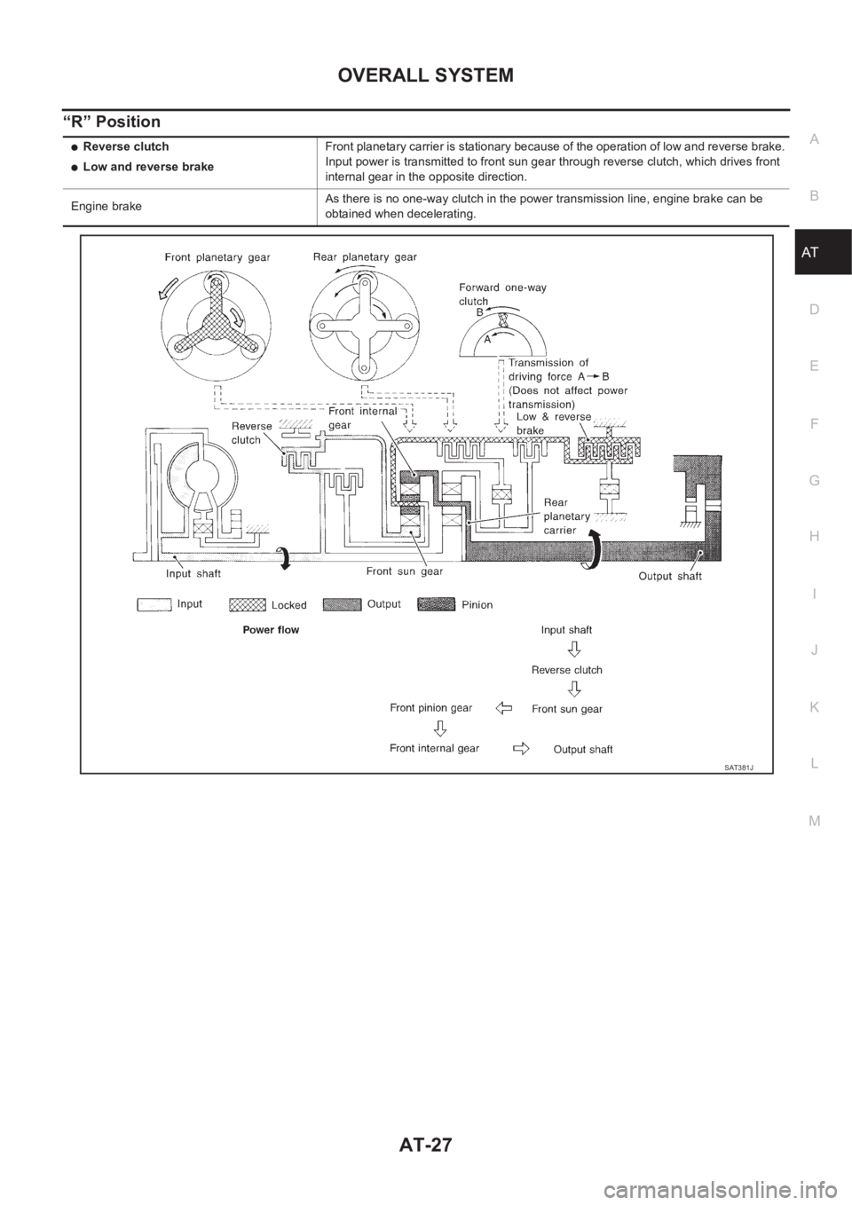
“R” Position
●Reverse clutch
●Low and reverse brakeFront planetary carrier is stationary because of the operation of low and reverse brake.
Input power is transmitted to front sun gear through reverse clutch, which drives front
internal gear in the opposite direction.
Engine brakeAs there is no one-way clutch in the power transmission line, engine brake can be
obtained when decelerating.
SAT381J
Page 2107 of 3833
OVERALL SYSTEM
AT-29
D
E
F
G
H
I
J
K
L
MA
B
AT
TCM FUNCTION
The function of the TCM is to:
●Receive input signals sent from various switches and sensors.
●Determine required line pressure, shifting point, lock-up operation, and engine brake operation.
●Send required output signals to the respective solenoids.
INPUT/OUTPUT SIGNAL OF TCM
Control MechanismECS004QF
LINE PRESSURE CONTROL
TCM has various line pressure control characteristics to match the driving conditions.
An ON-OFF duty signal is sent to the line pressure solenoid valve based on TCM characteristics.
Hydraulic pressure on the clutch and brake is electronically controlled through the line pressure solenoid valve
to accommodate engine torque. This results in smooth shift operation.
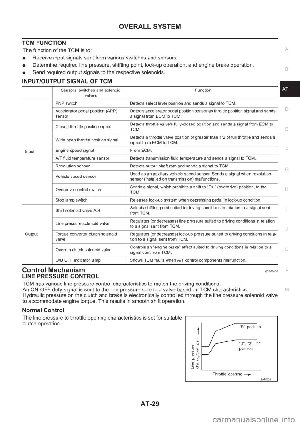
Normal Control
The line pressure to throttle opening characteristics is set for suitable
clutch operation.
Sensors, switches and solenoid
valvesFunction
InputPNP switch Detects select lever position and sends a signal to TCM.
Accelerator pedal position (APP)
sensorDetects accelerator pedal position sensor as throttle position signal and sends
a signal from ECM to TCM.
Closed throttle position signalDetects throttle valve's fully-closed position and sends a signal from ECM to
TCM.
Wide open throttle position signalDetects a throttle valve position of greater than 1/2 of full throttle and sends a
signal from ECM to TCM.
Engine speed signal From ECM.
A/T fluid temperature sensor Detects transmission fluid temperature and sends a signal to TCM.
Revolution sensor Detects output shaft rpm and sends a signal to TCM.
Vehicle speed sensorUsed as an auxiliary vehicle speed sensor. Sends a signal when revolution
sensor (installed on transmission) malfunctions.
Overdrive control switchSends a signal, which prohibits a shift to “D
4 ” (overdrive) position, to the
TCM.
Stop lamp switch Releases lock-up system when depressing pedal in lock-up condition.
OutputShift solenoid valve A/BSelects shifting point suited to driving conditions in relation to a signal sent
from TCM.
Line pressure solenoid valveRegulates (or decreases) line pressure suited to driving conditions in relation
to a signal sent from TCM.
Torque converter clutch solenoid
valveRegulates (or decreases) lock-up pressure suited to driving conditions in rela-
tion to a signal sent from TCM.
Overrun clutch solenoid valveControls an “engine brake” effect suited to driving conditions in relation to a
signal sent from TCM.
O/D OFF indicator lamp Shows TCM faults when A/T control components malfunction.
SAT003J
Page 2108 of 3833
AT-30
OVERALL SYSTEM
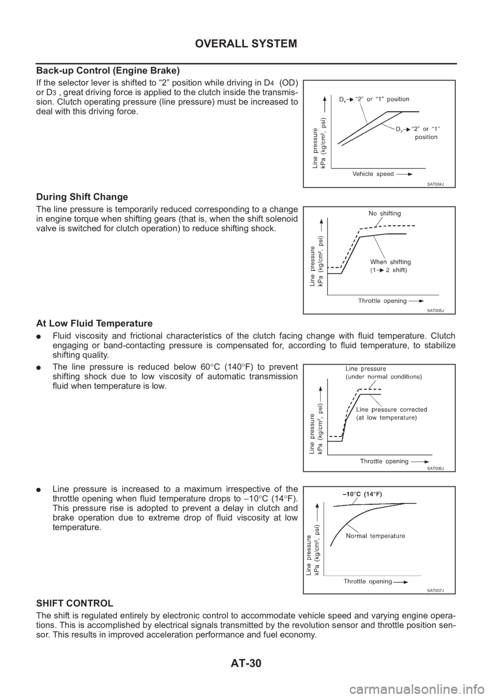
Back-up Control (Engine Brake)
If the selector lever is shifted to “2” position while driving in D4 (OD)
or D
3 , great driving force is applied to the clutch inside the transmis-
sion. Clutch operating pressure (line pressure) must be increased to
deal with this driving force.
During Shift Change
The line pressure is temporarily reduced corresponding to a change
in engine torque when shifting gears (that is, when the shift solenoid
valve is switched for clutch operation) to reduce shifting shock.
At Low Fluid Temperature
●Fluid viscosity and frictional characteristics of the clutch facing change with fluid temperature. Clutch
engaging or band-contacting pressure is compensated for, according to fluid temperature, to stabilize
shifting quality.
●The line pressure is reduced below 60°C (140°F) to prevent
shifting shock due to low viscosity of automatic transmission
fluid when temperature is low.
●Line pressure is increased to a maximum irrespective of the
throttle opening when fluid temperature drops to −10°C (14°F).
This pressure rise is adopted to prevent a delay in clutch and
brake operation due to extreme drop of fluid viscosity at low
temperature.
SHIFT CONTROL
The shift is regulated entirely by electronic control to accommodate vehicle speed and varying engine opera-
tions. This is accomplished by electrical signals transmitted by the revolution sensor and throttle position sen-
sor. This results in improved acceleration performance and fuel economy.
SAT004J
SAT005J
SAT006J
SAT007J
Page 2109 of 3833
OVERALL SYSTEM
AT-31
D
E
F
G
H
I
J
K
L
MA
B
AT
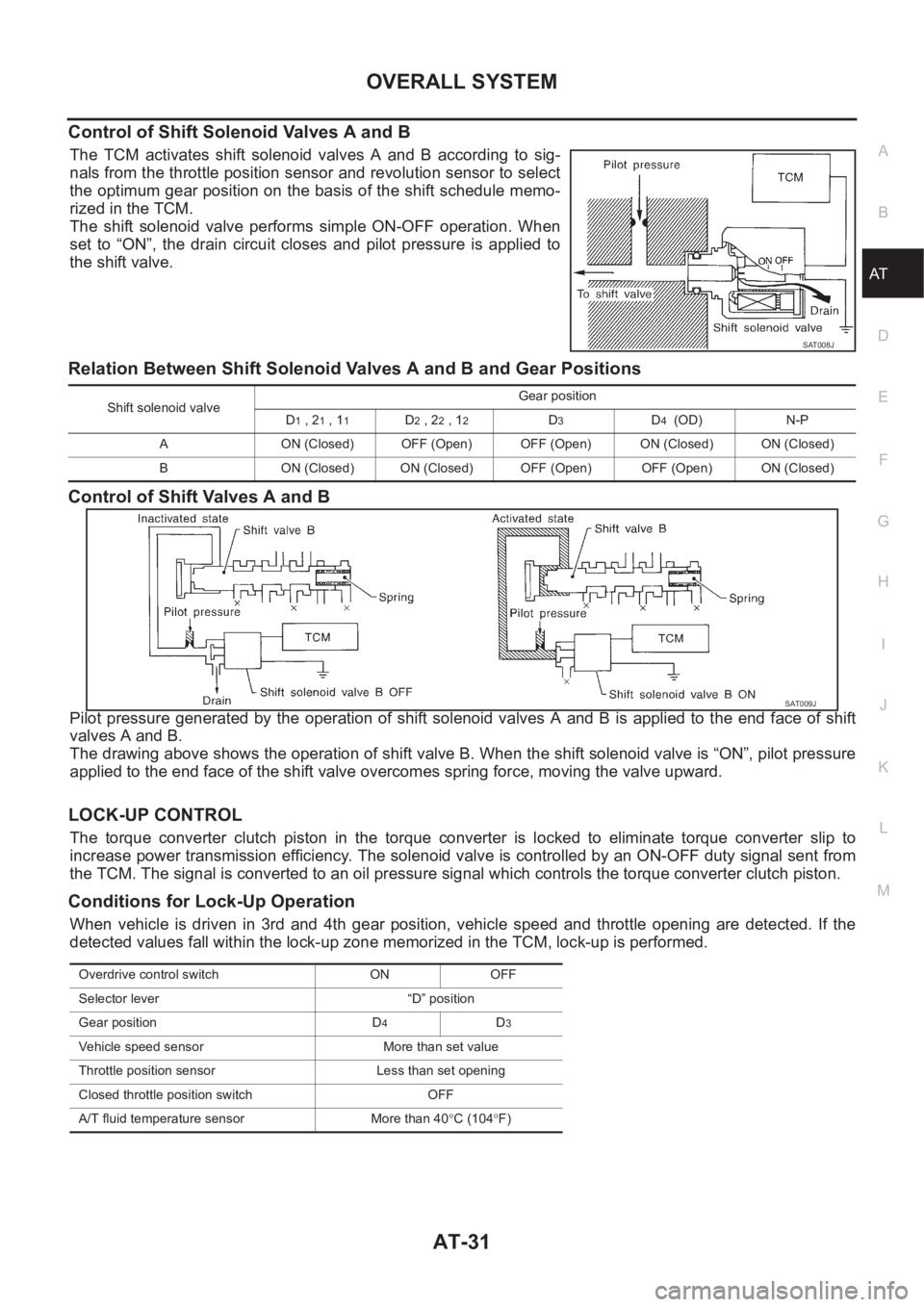
Control of Shift Solenoid Valves A and B
The TCM activates shift solenoid valves A and B according to sig-
nals from the throttle position sensor and revolution sensor to select
the optimum gear position on the basis of the shift schedule memo-
rized in the TCM.
The shift solenoid valve performs simple ON-OFF operation. When
set to “ON”, the drain circuit closes and pilot pressure is applied to
the shift valve.
Relation Between Shift Solenoid Valves A and B and Gear Positions
Control of Shift Valves A and B
Pilot pressure generated by the operation of shift solenoid valves A and B is applied to the end face of shift
valves A and B.
The drawing above shows the operation of shift valve B. When the shift solenoid valve is “ON”, pilot pressure
applied to the end face of the shift valve overcomes spring force, moving the valve upward.
LOCK-UP CONTROL
The torque converter clutch piston in the torque converter is locked to eliminate torque converter slip to
increase power transmission efficiency. The solenoid valve is controlled by an ON-OFF duty signal sent from
the TCM. The signal is converted to an oil pressure signal which controls the torque converter clutch piston.
Conditions for Lock-Up Operation
When vehicle is driven in 3rd and 4th gear position, vehicle speed and throttle opening are detected. If the
detected values fall within the lock-up zone memorized in the TCM, lock-up is performed.
SAT008J
Shift solenoid valveGear position
D1 , 21 , 11D2 , 22 , 12D3D4 (OD) N-P
A ON (Closed) OFF (Open) OFF (Open) ON (Closed) ON (Closed)
B ON (Closed) ON (Closed) OFF (Open) OFF (Open) ON (Closed)
SAT009J
Overdrive control switch ON OFF
Selector lever “D” position
Gear position D
4D3
Vehicle speed sensor More than set value
Throttle position sensor Less than set opening
Closed throttle position switch OFF
A/T fluid temperature sensor More than 40°C (104°F)
Page 2141 of 3833
TROUBLE DIAGNOSIS — BASIC INSPECTION
AT-63
[EURO-OBD]
D
E
F
G
H
I
J
K
L
MA
B
AT
TROUBLE DIAGNOSIS — BASIC INSPECTIONPFP:00000
A/T Fluid CheckECS004QQ
FLUID LEAKAGE CHECK
1. Clean area suspected of leaking. — for example, mating surface
of converter housing and transmission case.
2. Start engine, apply foot brake, place selector lever in “D” posi-
tion and wait a few minutes.
3. Stop engine.
4. Check for fresh leakage.
FLUID CONDITION CHECK
FLUID LEVEL CHECK
Refer to AT-13, "Checking A/T Fluid" .
SAT767B
SAT288G
Fluid color Suspected problem
Dark or black with burned odor Wear of frictional material
Milky pink Water contamination — Road water
entering through filler tube or breather
Varnished fluid, light to dark brown and
tackyOxidation — Over or under filling, —
Overheating
SAT638A
Page 2178 of 3833
![NISSAN X-TRAIL 2001 Service Repair Manual AT-100
[EURO-OBD]
TROUBLE DIAGNOSIS — GENERAL DESCRIPTION
Races extremely fast or slips in
changing from “D
4 ” or “D3 ” to “D1 ”
when depressing pedal.ON vehicle1. Fluid levelAT- 6 3](/manual-img/5/57405/w960_57405-2177.png "NISSAN X-TRAIL 2001 Service Repair Manual AT-100
[EURO-OBD]
TROUBLE DIAGNOSIS — GENERAL DESCRIPTION
Races extremely fast or slips in
changing from “D
4 ” or “D3 ” to “D1 ”
when depressing pedal.ON vehicle1. Fluid levelAT- 6 3")
AT-100
[EURO-OBD]
TROUBLE DIAGNOSIS — GENERAL DESCRIPTION
Races extremely fast or slips in
changing from “D
4 ” or “D3 ” to “D1 ”
when depressing pedal.ON vehicle1. Fluid levelAT- 6 3 , "
FLUID LEVEL
CHECK"
2. Accelerator pedal position (APP) sensorAT-180, "
DTC P1705
ACCELERATOR PEDAL
POSITION (APP) SEN-
SOR"
3. Line pressure testAT- 6 7 , "Line Pressure Test"
4. Line pressure solenoid valveAT-163, "
DTC P0745 LINE
PRESSURE SOLENOID
VA LV E"
5. Shift solenoid valve AAT-170, "
DTC P0750
SHIFT SOLENOID VALVE
A"
6. Shift solenoid valve BAT-175, "
DTC P0755
SHIFT SOLENOID VALVE
B"
7. Control valve assemblyAT-414, "
Control Valve
Assembly and Accumula-
tors"
OFF vehicle8. Forward clutchAT-471, "
Forward and
Overrun Clutches"
9. Forward one-way clutchAT-421, "OVERHAUL"
10. Low one-way clutchAT-421, "
OVERHAUL",AT-
425, "Locations of Adjust-
ing Shims, Needle Bear-
ings, Thrust Washers and
Snap Rings"
Vehicle will not run in any position.ON vehicle1. Fluid levelAT- 6 3 , "
FLUID LEVEL
CHECK"
2. Control cable adjustmentAT-416, "Control Cable
Adjustment"
3. Line pressure testAT- 6 7 , "Line Pressure Test"
4. Line pressure solenoid valveAT-163, "
DTC P0745 LINE
PRESSURE SOLENOID
VA LV E"
OFF vehicle5. Oil pumpAT-444, "
Oil Pump"
6. Torque converterAT-425, "
Locations of
Adjusting Shims, Needle
Bearings, Thrust Washers
and Snap Rings"
7. Parking componentsAT-421, "Components"
Transmission noise in “D”, “2”, “1”
and “R” positions.ON vehicle 1. Fluid levelAT- 6 3 , "
FLUID LEVEL
CHECK"
OFF vehicle 2. Torque converterAT-425, "
Locations of
Adjusting Shims, Needle
Bearings, Thrust Washers
and Snap Rings"
Symptom Condition Diagnostic ItemReference Page
EURO-OBD
Page 2180 of 3833
![NISSAN X-TRAIL 2001 Service Repair Manual AT-102
[EURO-OBD]
TROUBLE DIAGNOSIS — GENERAL DESCRIPTION
Does not change from “12 ” to “11 ”
in “1” position.ON vehicle1. PNP switchAT- 11 0 , "
DTC P0705
PARK/NEUTRAL POSI-
TIO](/manual-img/5/57405/w960_57405-2179.png "NISSAN X-TRAIL 2001 Service Repair Manual AT-102
[EURO-OBD]
TROUBLE DIAGNOSIS — GENERAL DESCRIPTION
Does not change from “12 ” to “11 ”
in “1” position.ON vehicle1. PNP switchAT- 11 0 , \"
DTC P0705
PARK/NEUTRAL POSI-
TIO")
AT-102
[EURO-OBD]
TROUBLE DIAGNOSIS — GENERAL DESCRIPTION
Does not change from “12 ” to “11 ”
in “1” position.ON vehicle1. PNP switchAT- 11 0 , "
DTC P0705
PARK/NEUTRAL POSI-
TION (PNP) SWITCH"
2. Vehicle speed sensor·A/T (Revolution
sensor) and vehicle speed sensor·MTRAT-122, "
DTC P0720 VEHI-
CLE SPEED SENSOR·A/T
(REVOLUTION SEN-
SOR)",AT- 1 9 9 , "DTC
VEHICLE SPEED SEN-
SOR MTR"
3. Shift solenoid valve AAT-170, "
DTC P0750
SHIFT SOLENOID VALVE
A"
4. Control valve assemblyAT-414, "
Control Valve
Assembly and Accumula-
tors"
OFF vehicle5. Low one-way clutchAT-421, "
OVERHAUL",AT-
425, "Locations of Adjust-
ing Shims, Needle Bear-
ings, Thrust Washers and
Snap Rings"
6. Brake bandAT-488, "Band Servo Pis-
ton Assembly"
7. Low & reverse brakeAT-476, "Low & Reverse
Brake"
Large shock changing from “12 ” to
“1
1 ” in “1” position.ON vehicle 1. Control valve assemblyAT-414, "
Control Valve
Assembly and Accumula-
tors"
OFF vehicle 2. Low & reverse brakeAT-476, "Low & Reverse
Brake"
Transmission overheats. ON vehicle1. Fluid levelAT- 6 3 , "
FLUID LEVEL
CHECK"
2. Engine idling rpmEC-38
[QR25 (WITH
EURO-OBD)], EC-448
[QR25 (WITHOUT EURO-
OBD)], EC-771
[QR20
(WITH EURO-OBD)], EC-
1135 [QR20 (WITHOUT
EURO-OBD)]
3. Accelerator pedal position (APP) sensorAT-180, "
DTC P1705
ACCELERATOR PEDAL
POSITION (APP) SEN-
SOR"
4. Line pressure testAT- 6 7 , "Line Pressure Test"
5. Line pressure solenoid valveAT-163, "
DTC P0745 LINE
PRESSURE SOLENOID
VA LV E"
6. Control valve assemblyAT-414, "
Control Valve
Assembly and Accumula-
tors"
Symptom Condition Diagnostic ItemReference Page
EURO-OBD
![NISSAN X-TRAIL 2001 Service Repair Manual TROUBLE DIAGNOSIS — BASIC INSPECTION
AT-63
[EURO-OBD]
D
E
F
G
H
I
J
K
L
MA
B
AT
TROUBLE DIAGNOSIS — BASIC INSPECTIONPFP:00000
A/T Fluid CheckECS004QQ
FLUID LEAKAGE CHECK
1. Clean area suspected of](/manual-img/5/57405/w960_57405-2140.png "NISSAN X-TRAIL 2001 Service Repair Manual TROUBLE DIAGNOSIS — BASIC INSPECTION
AT-63
[EURO-OBD]
D
E
F
G
H
I
J
K
L
MA
B
AT
TROUBLE DIAGNOSIS — BASIC INSPECTIONPFP:00000
A/T Fluid CheckECS004QQ
FLUID LEAKAGE CHECK
1. Clean area suspected of")