2001 NISSAN X-TRAIL transmission
[x] Cancel search: transmissionPage 1934 of 3833
![NISSAN X-TRAIL 2001 Service Repair Manual FL-10
[QR]
FUEL TANK
7. Remove exhaust center tube and insulator. Refer to EX-2, "EXHAUST SYSTEM" .
8. Remove propeller shaft. Refer to PR-2, "
REAR PROPELLER SHAFT" .
9. Using a tra](/manual-img/5/57405/w960_57405-1933.png "NISSAN X-TRAIL 2001 Service Repair Manual FL-10
[QR]
FUEL TANK
7. Remove exhaust center tube and insulator. Refer to EX-2, \"EXHAUST SYSTEM\" .
8. Remove propeller shaft. Refer to PR-2, \"
REAR PROPELLER SHAFT\" .
9. Using a tra")
FL-10
[QR]
FUEL TANK
7. Remove exhaust center tube and insulator. Refer to EX-2, "EXHAUST SYSTEM" .
8. Remove propeller shaft. Refer to PR-2, "
REAR PROPELLER SHAFT" .
9. Using a transmission jack, support the bottom of the rear final
drive.
10. Remove the mounting nuts on the rear suspension member, and
lower the transmission jack carefully until just before the rear
suspension member is removed from the stud bolts on the vehi-
cle.
11. Disconnect fuel filler hose, EVAP hose and vent hose at fuel
tank side.
12. For disconnection procedure of the quick connector on the
evaporator hose, Refer to FL-4, "
FUEL LEVEL SENSOR UNIT,
FUEL FILTER AND FUEL PUMP ASSEMBLY" .
13. Remove fuel tank protector.
14. Remove fuel tank band mounting bolts while supporting fuel
tank.
15. Remove fuel tank.
INSTALLATION
Install in the reverse order of removal paying attention to the following.
●Surely clamp fuel hoses and insert hose to the length below.
●Be sure hose clamp is not placed on swelled area of fuel tube.
●Tighten fuel hose clamp so that the distance between its lugs becomes to the following.
●Push the mounting band pin to the vehicle side securely.
●Before fixing the fuel tank, temporarily install the filler tube.
CAUTION:
Use genuine fuel filler tube mounting bolts or equivalent. Make sure to tighten them to the speci-
fied torque.
●To connect the quick connector, refer to FL-4, "FUEL LEVEL SENSOR UNIT, FUEL FILTER AND FUEL
PUMP ASSEMBLY" .
KBIA0285E
KBIA0286E
KBIA0290E
Fuel filler hose : 35mm (1.38 in)
The other hoses : 25mm (0.98 in)
Fuel tank side : 5 - 9 mm (0.20 - 0.35 in)
Fuel filler tube side : 7 - 11 mm (0.28 - 0.43 in)
Page 1946 of 3833
![NISSAN X-TRAIL 2001 Service Repair Manual FL-22
[YD22DDTi]
FUEL TANK
10. Using a transmission jack, support the bottom of the rear final
drive.
11. Remove the mounting nuts on the rear suspension member, and
lower the transmission](/manual-img/5/57405/w960_57405-1945.png "NISSAN X-TRAIL 2001 Service Repair Manual FL-22
[YD22DDTi]
FUEL TANK
10. Using a transmission jack, support the bottom of the rear final
drive.
11. Remove the mounting nuts on the rear suspension member, and
lower the transmission")
FL-22
[YD22DDTi]
FUEL TANK
10. Using a transmission jack, support the bottom of the rear final
drive.
11. Remove the mounting nuts on the rear suspension member, and
lower the transmission jack carefully until just before the rear
suspension member is removed from the stud bolts on the vehi-
cle.
12. Disconnect fuel filler hose, EVAP hose and vent hose at fuel
tank side.
For disconnection procedure of the quick connector. Refer to
FL-17, "
FUEL LEVEL SENSOR UNIT" .
13. Remove fuel tank protector.
14. Remove fuel tank band mounting bolts while supporting fuel
tank.
15. Remove fuel tank.
INSTALLATION
●Install in the reverse order of removal paying attention to the following.
●Surely clamp fuel hoses and insert hose to the length below.
●Be sure hose clamp is not positioned on swelled area of fuel tube.
●Tighten fuel hose clamp so that the distance between its lugs becomes to the following.
●Push the mounting band pin to the vehicle side securely.
●Before fixing the fuel tank, temporarily install the fuel filler tube.
CAUTION:
Use genuine fuel filler tube mounting bolts or equivalent. Make sure to tighten them to the speci-
fied torque.
●To connect the quick connector. Refer to FL-17, "FUEL LEVEL SENSOR UNIT" .
INSPECTION AFTER INSTALLATION
Make sure there is no fuel leakage at connections in the following steps.
KBIA0285E
KBIA0286E
KBIA0290E
Fuel filler hose : 35 mm (1.38 in)
The other hose : 25 mm (0.98 in)
Fuel tank side : 5 - 9 mm (0.20 - 0.35 in)
Fuel filler tube side : 7 - 11 mm (0.28 - 0.43 in)
Page 1959 of 3833
CL-1
CLUTCH
C TRANSMISSION/TRANSAXLE
CONTENTS
D
E
F
G
H
I
J
K
L
M
SECTION
A
B
CL
CLUTCH
PRECAUTIONS .......................................................... 2
Caution ..................................................................... 2
PREPARATION ........................................................... 3
Special Service Tools ............................................... 3
NOISE, VIBRATION, AND HARSHNESS (NVH)
TROUBLESHOOTING ................................................ 4
NVH Troubleshooting Chart ..................................... 4
CLUTCH ................................................................ 4
CLUTCH PEDAL ........................................................ 5
On-Vehicle Inspection and Adjustment .................... 5
HEIGHT ADJUSTMENT ....................................... 5
CLUTCH SWITCH POSITION ADJUSTMENT ..... 5
FREE PLAT INSPECTION .................................... 6
CLEARANCE CHECK ........................................... 6
Removal and Installation .......................................... 6
INSPECTION AFTER REMOVAL ......................... 7
CLUTCH FLUID .......................................................... 8
Air Bleeding Procedure ............................................ 8
CLUTCH MASTER CYLINDER .................................. 9
Removal and Installation .......................................... 9
REMOVAL ........................................................... 10
INSTALLATION ................................................... 10
Disassembly and Assembly ................................... 10
DISASSEMBLY ................................................... 10
INSPECTION AFTER DISASSEMBLY ............... 10
ASSEMBLY ......................................................... 10
OPERATING CYLINDER ...........................................11Removal and Installation ........................................ 11
REMOVAL ........................................................... 11
INSTALLATION ................................................... 11
Disassembly and Assembly .................................... 11
DISASSEMBLY ................................................... 11
INSPECTION AFTER DISASSEMBLY ................ 11
ASSEMBLY ......................................................... 11
CLUTCH PIPING ....................................................... 12
Removal and Installation ........................................ 12
CLUTCH RELEASE MECHANISM ........................... 13
Removal and Installation ........................................ 13
REMOVAL ........................................................... 13
INSPECTION AFTER REMOVAL ....................... 13
INSTALLATION ................................................... 13
CLUTCH DISC, CLUTCH COVER AND FLYWHEEL ... 15
Removal and Installation ........................................ 15
REMOVAL ........................................................... 15
INSPECTION AND ADJUSTMENT AFTER
REMOVAL ........................................................... 16
INSTALLATION ................................................... 17
SERVICE DATA AND SPECIFICATIONS (SDS) ...... 18
Clutch Control System ............................................ 18
Clutch Master Cylinder ........................................... 18
Clutch Operating Cylinder ...................................... 18
Clutch Disc ............................................................. 18
Clutch Cover ........................................................... 18
Clutch Pedal ........................................................... 18
Page 1977 of 3833
MT-1
MANUAL TRANSAXLE
C TRANSMISSION/TRANSAXLE
CONTENTS
D
E
F
G
H
I
J
K
L
M
SECTION
A
B
MT
MANUAL TRANSAXLE
PRECAUTIONS .......................................................... 3
Caution ..................................................................... 3
PREPARATION ........................................................... 4
Special Service Tools ............................................... 4
Commercial Service Tools ........................................ 6
NOISE, VIBRATION, AND HARSHNESS (NVH)
TROUBLESHOOTING ................................................ 7
NVH Troubleshooting Chart ..................................... 7
MANUAL TRANSAXLE ......................................... 7
DESCRIPTION ............................................................ 8
Cross-Sectional View ............................................... 8
DOUBLE-CONE SYNCHRONIZER ...................... 9
REVERSE GEAR NOISE PREVENTION FUNC-
TION (SYNCHRONIZING METHOD) ................... 9
M/T OIL ..................................................................... 10
Changing M/T Oil ................................................... 10
DRAINING ........................................................... 10
FILLING ............................................................... 10
Checking M/T Oil .................................................... 10
OIL LEAKAGE AND OIL LEVEL ......................... 10
SIDE OIL SEAL .........................................................11
Removal and Installation ......................................... 11
REMOVAL ............................................................ 11
INSTALLATION .................................................... 11
POSITION SWITCH .................................................. 12
Checking ................................................................ 12
BACK-UP LAMP SWITCH .................................. 12
PARK/NEUTRAL POSITION SWITCH ............... 12
CONTROL LINKAGE ............................................... 13
Removal and Installation of Control Device and
Cable ...................................................................... 13
AIR BREATHER HOSE ............................................ 14
Removal and Installation ........................................ 14
TRANSAXLE ASSEMBLY ........................................ 15
Removal and Installation ........................................ 15
REMOVAL ........................................................... 15
INSTALLATION ................................................... 16
Component Parts (RS5F51A) ................................ 17CASE AND HOUSING COMPONENTS .............. 17
GEAR COMPONENTS ....................................... 18
SHIFT CONTROL COMPONENTS ..................... 20
FINAL DRIVE COMPONENTS ........................... 21
Component Parts (RS6F51A) ................................. 22
CASE AND HOUSING COMPONENTS .............. 22
GEAR COMPONENTS ....................................... 23
SHIFT CONTROL COMPONENTS ..................... 25
FINAL DRIVE COMPONENTS ........................... 26
Disassembly and Assembly (RS5F51A) ................. 26
DISASSEMBLY ................................................... 26
ASSEMBLY ......................................................... 30
Disassembly and Assembly (RS6F51A) ................. 35
DISASSEMBLY ................................................... 35
ASSEMBLY ......................................................... 39
Adjustment (RS5F51A) ........................................... 45
INPUT SHAFT END PLAY .................................. 45
MAINSHAFT END PLAY ..................................... 46
DIFFERENTIAL SIDE BEARING PRELOAD ...... 47
REVERSE IDLER GEAR END PLAY .................. 48
Adjustment (RS6F51A) ........................................... 49
INPUT SHAFT END PLAY .................................. 49
MAINSHAFT END PLAY ..................................... 50
DIFFERENTIAL SIDE BEARING PRELOAD ...... 51
REVERSE IDLER GEAR END PLAY .................. 52
INPUT SHAFT AND GEARS .................................... 54
Assembly and Disassembly (RS5F51A) ................. 54
DISASSEMBLY ................................................... 54
INSPECTION AFTER DISASSEMBLY ................ 55
ASSEMBLY ......................................................... 57
Assembly and Disassembly (RS6F51A) ................. 61
DISASSEMBLY ................................................... 61
INSPECTION AFTER DISASSEMBLY ................ 62
ASSEMBLY ......................................................... 64
MAINSHAFT AND GEARS ....................................... 68
Assembly and Disassembly (RS5F51A) ................. 68
DISASSEMBLY ................................................... 68
INSPECTION AFTER DISASSEMBLY ................ 69
Page 2079 of 3833
AT-1
AUTOMATIC TRANSAXLE
C TRANSMISSION/TRANSAXLE
CONTENTS
D
E
F
G
H
I
J
K
L
M
SECTION
A
B
AT
AUTOMATIC TRANSAXLE
PRECAUTIONS .......................................................... 5
Precautions for Supplemental Restraint System
(SRS) “AIR BAG” and “SEAT BELT PRE-TEN-
SIONER” .................................................................. 5
Precautions for On Board Diagnostic (EURO-OBD)
System of A/T and Engine — Euro-OBD — ............. 5
Precautions for Trouble Diagnosis ........................... 5
Precautions for Harness Repair ............................... 5
Precautions .............................................................. 6
Service Notice or Precautions .................................. 7
Wiring Diagrams and Trouble Diagnosis .................. 8
PREPARATION ........................................................... 9
Special Service Tools ............................................... 9
Commercial Service Tools ...................................... 12
A/T FLUID ................................................................. 13
Checking A/T Fluid ................................................. 13
Changing A/T Fluid ............................................. ... 13
OVERALL SYSTEM ................................................. 14
A/T Electrical Parts Location .................................. 14
Circuit Diagram ...................................................... 15
Cross-Sectional View ............................................. 16
Hydraulic Control Circuit ........................................ 17
Shift Mechanism ..................................................... 18
Control System ....................................................... 28
Control Mechanism ................................................ 29
Control Valve .......................................................... 34
EURO-OBD
TROUBLE DIAGNOSIS — INDEX ........................... 35
Alphabetical & P No. Index for DTC ....................... 35
ON BOARD DIAGNOSTIC SYSTEM DESCRIP-
TION .......................................................................... 37
Introduction ............................................................ 37
EURO-OBD Function for A/T System .................... 37
One or Two Trip Detection Logic of EURO-OBD ... 37
EURO-OBD Diagnostic Trouble Code (DTC) ......... 37
Malfunction Indicator lamp (MIL) ............................ 41
CONSULT-II ........................................................... 41
Diagnostic Procedure Without CONSULT-II ........... 50TROUBLE DIAGNOSIS — INTRODUCTION ........... 56
Introduction ............................................................. 56
Work Flow ............................................................... 60
TROUBLE DIAGNOSIS — BASIC INSPECTION .... 63
A/T Fluid Check ...................................................... 63
Stall Test ................................................................. 64
Line Pressure Test .................................................. 67
Road Test ............................................................... 68
TROUBLE DIAGNOSIS — GENERAL DESCRIP-
TION .......................................................................... 86
Symptom Chart ....................................................... 86
TCM Terminals and Reference Value ...................106
CAN COMMUNICATION .........................................109
System Description ...............................................109
DTC P0705 PARK/NEUTRAL POSITION (PNP)
SWITCH ..................................................................110
Description ............................................................110
Wiring Diagram — AT — PNP/SW .......................112
Diagnostic Procedure ...........................................113
Component Inspection ..........................................115
DTC P0710 A/T FLUID TEMPERATURE SENSOR
CIRCUIT ..................................................................116
Description ............................................................116
Wiring Diagram — AT — FTS ..............................118
Diagnostic Procedure ...........................................119
Component Inspection ..........................................121
DTC P0720 VEHICLE SPEED SENSOR·A/T (REV-
OLUTION SENSOR) ...............................................122
Description ............................................................122
Wiring Diagram — AT — VSSA/T ........................124
Diagnostic Procedure ...........................................125
DTC P0725 ENGINE SPEED SIGNAL ...................127
Description ............................................................127
Wiring Diagram — AT — ENGSS .........................128
Diagnostic Procedure ...........................................129
DTC P0731 A/T 1ST GEAR FUNCTION ...............
.131
Description ............................................................131
Wiring Diagram — AT — 1ST ...............................134
Diagnostic Procedure ...........................................135
Component Inspection ..........................................136
Page 2087 of 3833
PREPARATION
AT-9
D
E
F
G
H
I
J
K
L
MA
B
AT
PREPARATIONPFP:00100
Special Service ToolsECS004Q5
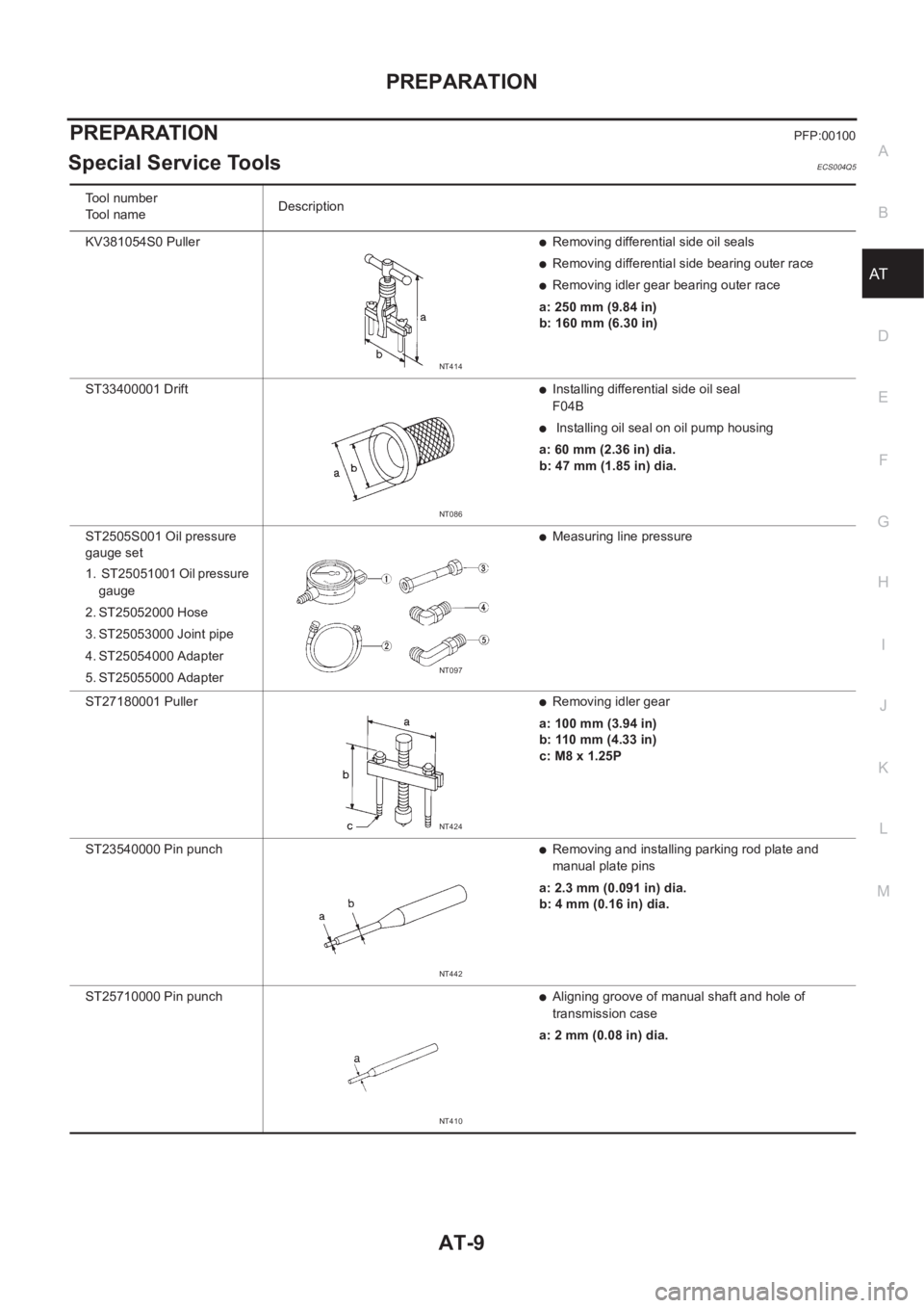
Tool number
Tool nameDescription
KV381054S0 Puller
●Removing differential side oil seals
●Removing differential side bearing outer race
●Removing idler gear bearing outer race
a: 250 mm (9.84 in)
b: 160 mm (6.30 in)
ST33400001 Drift
●Installing differential side oil seal
F04B
● Installing oil seal on oil pump housing
a: 60 mm (2.36 in) dia.
b: 47 mm (1.85 in) dia.
ST2505S001 Oil pressure
gauge set
1. ST25051001 Oil pressure
gauge
2. ST25052000 Hose
3. ST25053000 Joint pipe
4. ST25054000 Adapter
5. ST25055000 Adapter
●Measuring line pressure
ST27180001 Puller
●Removing idler gear
a: 100 mm (3.94 in)
b: 110 mm (4.33 in)
c: M8 x 1.25P
ST23540000 Pin punch
●Removing and installing parking rod plate and
manual plate pins
a: 2.3 mm (0.091 in) dia.
b: 4 mm (0.16 in) dia.
ST25710000 Pin punch
●Aligning groove of manual shaft and hole of
transmission case
a: 2 mm (0.08 in) dia.
NT414
NT086
NT097
NT424
NT442
NT410
Page 2097 of 3833
OVERALL SYSTEM
AT-19
D
E
F
G
H
I
J
K
L
MA
B
AT
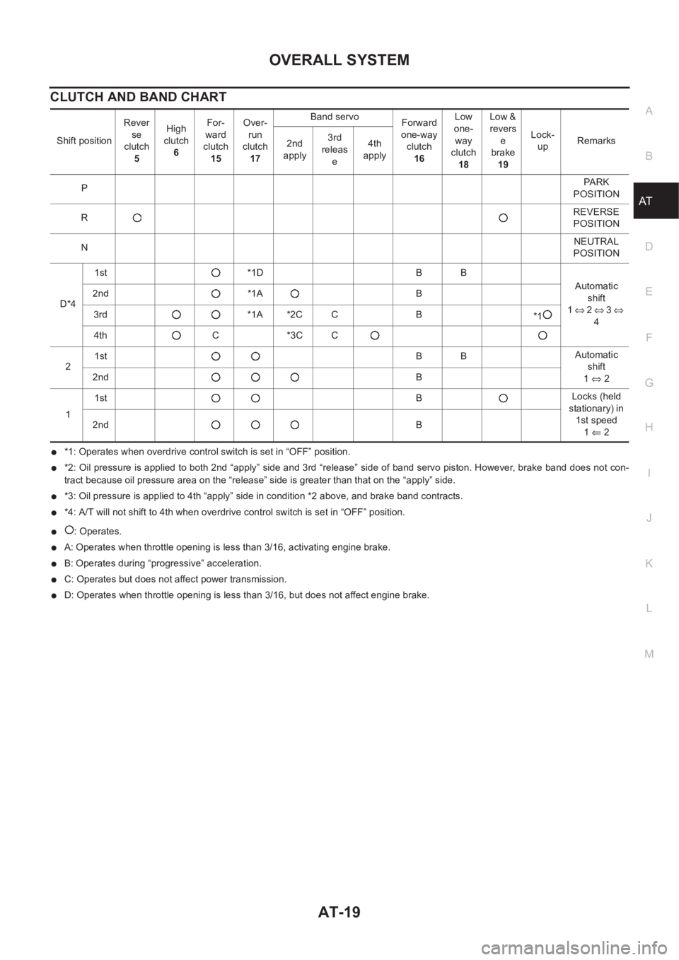
CLUTCH AND BAND CHART
●*1: Operates when overdrive control switch is set in “OFF” position.
●*2: Oil pressure is applied to both 2nd “apply” side and 3rd “release” side of band servo piston. However, brake band does not con-
tract because oil pressure area on the “release” side is greater than that on the “apply” side.
●*3: Oil pressure is applied to 4th “apply” side in condition *2 above, and brake band contracts.
●*4: A/T will not shift to 4th when overdrive control switch is set in “OFF” position.
●: Operates.
●A: Operates when throttle opening is less than 3/16, activating engine brake.
●B: Operates during “progressive” acceleration.
●C: Operates but does not affect power transmission.
●D: Operates when throttle opening is less than 3/16, but does not affect engine brake. Shift positionRever
se
clutch
5High
clutch
6For-
ward
clutch
15Over-
run
clutch
17Band servo
Forward
one-way
clutch
16Low
one-
way
clutch
18Low &
revers
e
brake
19Lock-
upRemarks
2nd
apply3rd
releas
e4th
apply
PPA R K
POSITION
RREVERSE
POSITION
NNEUTRAL
POSITION
D*41st *1D B B
Automatic
shift
1⇔ 2 ⇔ 3 ⇔
4 2nd *1A B
3rd *1A *2C C B
*1
4th C *3C C
21stBBAutomatic
shift
1⇔ 2 2ndB
11stBLocks (held
stationary) in
1st speed
1⇐ 2 2ndB
Page 2099 of 3833
OVERALL SYSTEM
AT-21
D
E
F
G
H
I
J
K
L
MA
B
AT
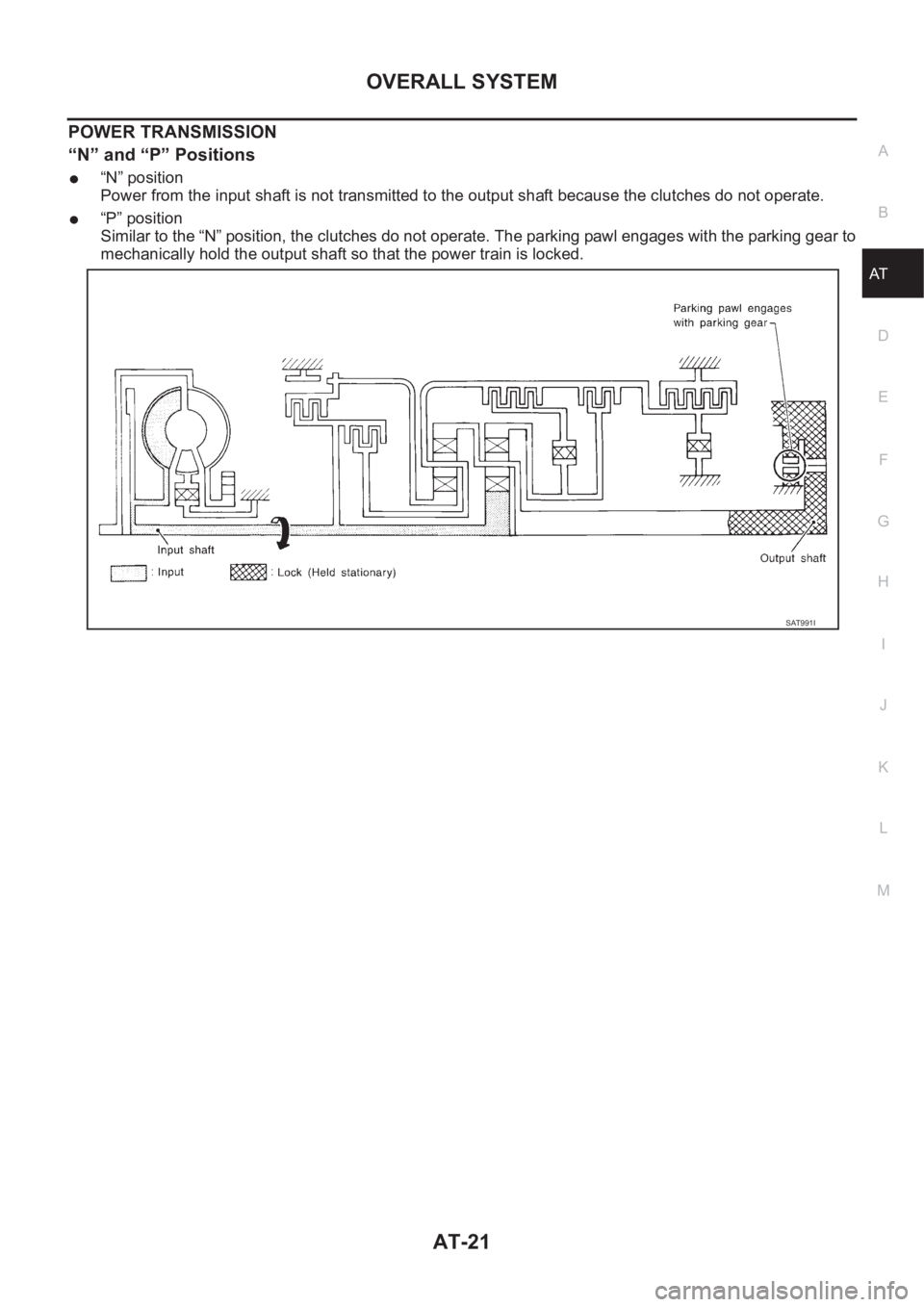
POWER TRANSMISSION
“N” and “P” Positions
●“N” position
Power from the input shaft is not transmitted to the output shaft because the clutches do not operate.
●“P” position
Similar to the “N” position, the clutches do not operate. The parking pawl engages with the parking gear to
mechanically hold the output shaft so that the power train is locked.
SAT991I