2001 NISSAN X-TRAIL oil
[x] Cancel search: oilPage 3426 of 3833
ATC-150
SERVICE DATA AND SPECIFICATIONS (SDS)
SERVICE DATA AND SPECIFICATIONS (SDS)
PFP:00030
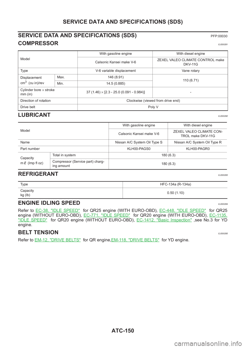
COMPRESSOREJS00281
LUBRICANTEJS00282
REFRIGERANTEJS00283
ENGINE IDLING SPEEDEJS00284
Refer to EC-38, "IDLE SPEED" for QR25 engine (WITH EURO-OBD), EC-448, "IDLE SPEED" for QR25
engine (WITHOUT EURO-OBD), EC-771, "
IDLE SPEED" for QR20 engine (WITH EURO-OBD), EC-1135,
"IDLE SPEED" for QR20 engine (WITHOUT EURO-OBD), EC-1412, "Basic Inspection" ,see No.3 for YD
engine.
BELT TENSIONEJS00285
Refer to EM-12, "DRIVE BELTS" for QR engine,EM-118, "DRIVE BELTS" for YD engine.
ModelWith gasoline engine With diesel engine
Calsonic Kansei make V-6ZEXEL VALEO CLIMATE CONTROL make
DKV-11G
Type V-6 variable displacement Vane rotary
Displacement
cm
3 (cu in)/revMax. 146 (8.91)
110 (6.71)
Min. 14.5 (0.885)
Cylinder bore × stroke
mm (in)37 (1.46) × [2.3 - 25.0 (0.091 - 0.984)] -
Direction of rotation Clockwise (viewed from drive end)
Drive beltPoly V
ModelWith gasoline engine With diesel engine
Calsonic Kansei make V-6ZEXEL VALEO CLIMATE CON-
TROL make DKV-11G
Name Nissan A/C System Oil Type S Nissan A/C System Oil Type R
Part number KLH00-PAGS0 KLH00-PAGR0
Capacity
m (lmp fl oz)Total in system 180 (6.3)
Compressor (Service part) charg-
ing amount180 (6.3)
Ty p eHFC-134a (R-134a)
Capacity
kg (lb)0.50 (1.10)
Page 3470 of 3833

SC-14
CHARGING SYSTEM
Trouble Diagnoses
EKS00319
Before conducting an alternator test, make sure that the battery is fully charged. A 30-volt voltmeter and suit-
able test probes are necessary for the test. The alternator can be checked easily by referring to the Inspection
Ta b l e .
●Before starting, inspect the fusible link.
●Use fully charged battery.
WITH IC REGULATOR
NOTE:
●If the inspection result is OK even though the charging system is malfunctioning, check the B terminal
connection. (Check the tightening torque.)
●When field circuit is open, check condition of rotor coil, rotor slip ring and brush. If necessary, replace
faulty parts with new ones.
MALFUNCTION INDICATOR
The IC regulator warning function activates to illuminate “CHARGE” warning lamp, if any of the following
symptoms occur while alternator is operating:
●Excessive voltage is produced.
●No voltage is produced.
SEL338V
Page 3489 of 3833

SC-33
C
D
E
F
G
H
I
J
L
MA
B
SC
SERVICE DATA AND SPECIFICATIONS (SDS)PFP:00030
BatteryEKS0031Q
StarterEKS0031R
AlternatorEKS0031S
Applied model QR20, QR25 engine")
SERVICE DATA AND SPECIFICATIONS (SDS)
SC-33
C
D
E
F
G
H
I
J
L
MA
B
SC
SERVICE DATA AND SPECIFICATIONS (SDS)PFP:00030
BatteryEKS0031Q
StarterEKS0031R
AlternatorEKS0031S
Applied model QR20, QR25 engine
YD22 engine Except for Northern Europe
For Northern Europe
Standard Option
Type 55D23L 80D26L 110D26L
Capacity V-AH 12-48 12-55 12-64
TypeS114-844 M0T87081 M8T71471
HITACHI make MITSUBISHI make
Reduction
Applied modelQR20, QR25 engine
YD22 engine
A/T M/T
System voltage V12
No-loadTerminal voltage V 11.0
Current A Less than 90 Less than 90 Less than 145
Revolution rpm More than 2,700 More than 2,500 More than 3,300
Minimum diameter of commutator mm (in) 28.0 (1.102) 28.8 (1.134) 31.4 (1.236)
Minimum length of brush mm (in) 10.5 (0.413) 7.0 (0.276) 11.0 (0.433)
Brush spring tension N (kg, lb) 16.2(1.65, 3.64)15.0 - 20.4(1.5 - 2.1, 3.4
- 4.6)26.7 - 36.1(2.7 - 3.7, 6.0
- 8.2)
Clearance between bearing metal and armature
shaft mm (in)Less than 0.2 (0.008) —
Clearance “l” between pinion front edge and pinion
stopper mm (in)0.3 - 2.5 (0.012 - 0.098) 0.5 - 2.0(0.020 - 0.079) —
Movement “l” in height of pinion assembly mm (in) — 0.5 - 2.0(0.020 - 0.079)
TypeLR1110-713 A3TB0771
HITACHI make MITSUBISHI make
Applied model QR20, QR25 engine YD22 engine
Nominal rating V-A 12-110 12-90
Ground polarityNegative
Minimum revolutions under no-load (When 13.5V is
applied) rpmLess than 1,100 Less than 1,300
Hot output current (When 13.5V is applied) A/rpmMore than35/1,300
More than91/2,500
More than110/5,000More than29/1,300
More than76/2,500
More than88/5,000
Regulated output voltage V 14.1 - 14.7
Minimum length of brush mm (in) More than 6.0 (0.236) More than 5.0 (0.197)
Brush spring pressure N (g, oz) 1.0 - 3.43 (102 - 350, 3.60 - 12.34) 4.8 - 6.0 (490 - 610, 17.28 - 21.51)
Slip ring minimum diameter mm (in) More than 26.0 (1.024) More than 22.1 (0.870)
Rotor coil resistance at 20° (68°F) Ω2.31 2.1 - 2.5
Page 3493 of 3833
 “AIR BAG” and “SEAT
BELT PRE-TENSIONER”
EKS0079M
The Supplemental Restrain")
PRECAUTION
LT-3
C
D
E
F
G
H
I
J
L
MA
B
LT
PRECAUTION PFP:00011
Precautions for Supplemental Restraint System (SRS) “AIR BAG” and “SEAT
BELT PRE-TENSIONER”
EKS0079M
The Supplemental Restraint System such as “AIR BAG” and “SEAT BELT PRE-TENSIONER”, used along
with a front seat belt, helps to reduce the risk or severity of injury to the driver and front passenger for certain
types of collision. Information necessary to service the system safely is included in the SRS and SB section of
this Service Manual.
WARNING:
●To avoid rendering the SRS inoperative, which could increase the risk of personal injury or death
in the event of a collision which would result in air bag inflation, all maintenance must be per-
formed by an authorized NISSAN/INFINITI dealer.
●Improper maintenance, including incorrect removal and installation of the SRS, can lead to per-
sonal injury caused by unintentional activation of the system. For removal of Spiral Cable and Air
Bag Module, see the SRS section.
●Do not use electrical test equipment on any circuit related to the SRS unless instructed to in this
Service Manual. SRS wiring harnesses can be identified by yellow and/or orange harness connec-
tors.
Precaution EKS003KS
●Do not touch the glass of bulb directly by hand. Keep grease and other oily matters away from it. Do not
touch bulb by hand while it is lit or right after being turned off. Burning may result.
●Do not leave bulb out of headlamp reflector for a long time because dust, moisture smoke, etc. may affect
the performance of the headlamp. When replacing the bulb, be sure to replace it with a new one.
●Adjust aiming by tightening aiming screw. (To adjust it toward loosening side, first loosen adjusting screw,
and then make adjustment by tightening.)
●To remove soil or sealant of bulbs, do not use organic solvent (thinner, gasoline, etc.)
●When replacing bulb, be sure to hold bulb socket and pull it out straight. If wiring harness of the bulb is
pulled at an angle, the bulb may be caught in the lamp, making it difficult to take out.
Wiring Diagrams and Trouble Diagnosis EKS003KT
When you read wiring diagrams, refer to the followings:
●Refer to GI-13, "How to Read Wiring Diagrams" in GI section
●Refer to PG-2, "POWER SUPPLY ROUTING" for power distribution circuit in PG section
When you perform trouble diagnosis, refer to the followings:
●Refer to GI-10, "HOW TO FOLLOW TEST GROUPS IN TROUBLE DIAGNOSES" in GI section
●Refer toGI-23, "How to Perform Efficient Diagnosis for an Electrical Incident" in GI section
Page 3496 of 3833

LT-6
HEADLAMP
Trouble Diagnoses
EKS003CF
Aiming Adjustment EKS003CG
When performing headlamp aiming adjustment, use an aiming machine, aiming wall screen or headlamp
tester. Aimers should be in good repair, calibrated and operated in accordance with respective operation man-
uals.
If any aimer is not available, aiming adjustment can be done as follows:
For details, refer to the regulations in your own country.
●Keep all tires inflated to correct pressures.
●Place vehicle and tester on one and same flat surface.
●See that there is no-load in vehicle (coolant, engine oil filled up to correct level and full fuel tank) other
than the driver (or equivalent weight placed in driver's position).
Symptom Possible cause Repair order
Headlamp LH do not operate.1. Bulb
2. Grounds E24 and E50
3. 15A fuse
4. Lighting switch1. Check bulb.
2. Check grounds E24 and E50.
3. Check 15A fuse (No. 40, located in fuse
and fusible link box). Verify battery posi-
tive voltage is present at terminal 8 of
lighting switch.
4. Check lighting switch.
Headlamp RH do not operate.1. Bulb
2. Grounds E24 and E50
3. 15A fuse
4. Lighting switch1. Check bulb.
2. Check grounds E24 and E50.
3. Check 15A fuse (No. 41, located in fuse
and fusible link box). Verify battery posi-
tive voltage is present at terminal 5 of
lighting switch.
4. Check lighting switch.
High beam LH do not operate, but low
beam LH operates.1. Bulb
2. Open in high beam LH circuit
3. Lighting switch1. Check bulbs.
2. Check the wire between lighting switch
terminal 9 and headlamp LH terminal 1
for an open circuit.
3. Check lighting switch.
Low beam LH does not operate, but high
beam LH operates.1. Bulb
2. Open in low beam LH circuit
3. Lighting switch1. Check bulb.
2. Check the wire between lighting switch
terminal 10 and headlamp LH terminal 3
for an open circuit.
3. Check lighting switch.
High beam RH do not operate, but low
beam RH operates.1. Bulb
2. Open in high beam RH circuit
3. Lighting switch1. Check bulbs.
2. Check the wire between lighting switch
terminal 6 and headlamp RH terminal 1
for an open circuit.
3. Check lighting switch.
Low beam RH does not operate, but high
beam RH operates.1. Bulb
2. Open in low beam RH circuit
3. Lighting switch1. Check bulb.
2. Check the wire between lighting switch
terminal 7 and headlamp RH terminal 3
for an open circuit.
3. Check lighting switch.
High beam indicator does not work.1. Bulb
2. Grounds M27 and M70
3. Open in high beam circuit1. Check bulb in combination meter.
2. Check grounds M27 and M70.
3. Check the wire between lighting switch
terminal 9 and combination meter termi-
nal 61(LHD models) or 50(RHD models)
for an open circuit.
Page 3498 of 3833

LT-8
HEADLAMP
Bulb Replacement
EKS003CH
HEAD LAMP
1. Disconnect connector of headlamp.
2. Remove rubber cap.
3. Unlock retaining spring, then remove bulb.
CLEARANCE LAMP
1. Turn the RH bulbsocket clockwise and unlock it.
Turn the LH bulbsocket counterclockwise and unlock it.
2. Remove the bulb from its socket.
CAUTION:
●Do not touch the glass of bulb directly by hand. Keep grease and other oily matters away from it.
Do not touch bulb by hand while it is lit or right after being turned off. Burning may result.
●Do not leave bulb out of headlamp reflector for a long time because dust, moisture smoke, etc.
may affect the performance of headlamp. When replacing bulb, be sure to replace it with new one.
●When bulb is installed, be sure to lock rubber cap to ensure watertightness.
Removal and Installation EKS003CI
REMOVAL
1. Remove the front turn signal lamps. Refer toLT- 2 2 , "Removal
and Installation for Front Turn Signal Lamp"
2. Disconnect connector of headlamp and clearance lamp.
3. Remove the front grille. Refer to EI-11, "
FRONT GRILLE" in
"EXTERIOR & INTERIOR (EI)" section.
4. Remove the headlamp mounting bolts.
5. Pull the headlamp toward the front of the vehicle.
INSTALLATION
●Install in the reverse order of removal, taking care of the following points.
Headlamp mounting boltsHeadlamp (High/Low) : 12V 60/55 W(H4)
SKIA0073E
Clearance lamp : 12V 5W
SKIA0050E
Tightening torque : 4.5 - 6.4 N-m (0.45 - 0.65 kg-m, 39 - 56 in-lb)
Page 3526 of 3833

LT-36
FRONT FOG LAMP
Bulb Replacement
EKS003DI
1. Remove fog lamp. Refer toLT-36, "Removal and Installation" .
2. Turn plastic cap counter clockwise then remove it.
3. Unlock retaining spring, then remove bulb.
CAUTION:
●Do not touch the glass of bulb directly by hand. Keep
grease and other oily matters away from it. Do not touch
bulb by hand while it is lit or right after being turned off.
Burning may result.
●Do not leave bulb out of headlamp reflector for a long time
because dust, moisture smoke, etc. May affect the performance of headlamp. When replacing
bulb, be sure to replace it with new one.
●When bulb is installed, be sure to lock plastic cap to ensure watertightness.
Removal and Installation EKS003DJ
REMOVAL
1. Remove fender protector. Refer toEI-13, "FENDER PROTECTOR"
2. Disconnect fog lamp connector.
3. Remove fog lamp mounting bolt.
4. Pull out fog lamp from vehicle and disconnect connector.
INSTALLATION
●Install fog lamp in the reverse order of removal, observing the tightening torque shown below.
Fog lamp mounting boltFront fog lamp :12 V 55 W (H3)
PKIA0546E
PKIA0547E
Tightening torque :3.3 -7.7 N-m (0.33 - 0.79 kg-m, 29 - 69 in-lb)
Page 3560 of 3833

DI-2
Engine Models ........................................................ 35
Inspection/Vehicle speed signal ............................. 35
Inspection/Fuel Level Sensor Unit .......................... 37
FUEL LEVEL SENSOR UNIT .............................. 37
LOW-FUEL WARNING LAMP ............................. 37
The Fuel Gauge Pointer Fluctuates·Indicator
Wrong Value·or Varies. ........................................... 38
The Fuel Gauge Does Not Move to Full-position. ... 39
The Fuel Gauge Does Not Work. ........................... 39
Low Fuel Warning Lamp Illuminate or Not Illuminate ... 40
Electrical Components Inspection .......................... 41
FUEL LEVEL SENSOR UNIT CHECK / GASO-
LINE ENGINE MODELS ...................................... 41
FUEL LEVEL SENSOR UNIT CHECK / DIESEL
ENGINE MODELS ............................................... 41
THERMAL TRANSMITTER CHECK ................... 42
Removal and Installation for Combination Meter .... 42
Disassembly and Assembly for Combination Meter ... 42
WARNING LAMPS .................................................... 43
Schematic ............................................................... 43
Wiring Diagram — WARN —/ LHD Models ............ 44Wiring Diagram — WARN — / RHD Models ........... 50
Electrical Components Inspection ........................... 56
FUEL WARNING LAMP OPERATION CHECK ... 56
OIL PRESSURE SWITCH CHECK ...................... 56
DIODE CHECK .................................................... 56
A/T INDICATOR ......................................................... 57
Wiring Diagram — AT/IND — ................................. 57
WARNING CHIME .................................................. ... 58
System Description ................................................. 58
POWER SUPPLY AND GROUND CIRCUIT ....... 58
IGNITION KEY WARNING CHIME ...................... 58
LIGHT WARNING CHIME ................................... 58
SEAT BELT WARNING CHIME ........................... 58
Wiring Diagram — CHIME — ................................. 59
Symptom Chart ....................................................... 61
Power Supply and Ground Circuit Check ............... 62
Lighting Switch Input Signal Check ......................... 63
Key Switch Insert Signal Check .............................. 65
Door Unlock Sensor Check ..................................... 66
Front Door Switch (driver side) Check .................... 68
CLOCK ...................................................................... 70
Wiring Diagram — CLOCK — ................................. 70