2001 NISSAN X-TRAIL belt
[x] Cancel search: beltPage 2079 of 3833
AT-1
AUTOMATIC TRANSAXLE
C TRANSMISSION/TRANSAXLE
CONTENTS
D
E
F
G
H
I
J
K
L
M
SECTION
A
B
AT
AUTOMATIC TRANSAXLE
PRECAUTIONS .......................................................... 5
Precautions for Supplemental Restraint System
(SRS) “AIR BAG” and “SEAT BELT PRE-TEN-
SIONER” .................................................................. 5
Precautions for On Board Diagnostic (EURO-OBD)
System of A/T and Engine — Euro-OBD — ............. 5
Precautions for Trouble Diagnosis ........................... 5
Precautions for Harness Repair ............................... 5
Precautions .............................................................. 6
Service Notice or Precautions .................................. 7
Wiring Diagrams and Trouble Diagnosis .................. 8
PREPARATION ........................................................... 9
Special Service Tools ............................................... 9
Commercial Service Tools ...................................... 12
A/T FLUID ................................................................. 13
Checking A/T Fluid ................................................. 13
Changing A/T Fluid ............................................. ... 13
OVERALL SYSTEM ................................................. 14
A/T Electrical Parts Location .................................. 14
Circuit Diagram ...................................................... 15
Cross-Sectional View ............................................. 16
Hydraulic Control Circuit ........................................ 17
Shift Mechanism ..................................................... 18
Control System ....................................................... 28
Control Mechanism ................................................ 29
Control Valve .......................................................... 34
EURO-OBD
TROUBLE DIAGNOSIS — INDEX ........................... 35
Alphabetical & P No. Index for DTC ....................... 35
ON BOARD DIAGNOSTIC SYSTEM DESCRIP-
TION .......................................................................... 37
Introduction ............................................................ 37
EURO-OBD Function for A/T System .................... 37
One or Two Trip Detection Logic of EURO-OBD ... 37
EURO-OBD Diagnostic Trouble Code (DTC) ......... 37
Malfunction Indicator lamp (MIL) ............................ 41
CONSULT-II ........................................................... 41
Diagnostic Procedure Without CONSULT-II ........... 50TROUBLE DIAGNOSIS — INTRODUCTION ........... 56
Introduction ............................................................. 56
Work Flow ............................................................... 60
TROUBLE DIAGNOSIS — BASIC INSPECTION .... 63
A/T Fluid Check ...................................................... 63
Stall Test ................................................................. 64
Line Pressure Test .................................................. 67
Road Test ............................................................... 68
TROUBLE DIAGNOSIS — GENERAL DESCRIP-
TION .......................................................................... 86
Symptom Chart ....................................................... 86
TCM Terminals and Reference Value ...................106
CAN COMMUNICATION .........................................109
System Description ...............................................109
DTC P0705 PARK/NEUTRAL POSITION (PNP)
SWITCH ..................................................................110
Description ............................................................110
Wiring Diagram — AT — PNP/SW .......................112
Diagnostic Procedure ...........................................113
Component Inspection ..........................................115
DTC P0710 A/T FLUID TEMPERATURE SENSOR
CIRCUIT ..................................................................116
Description ............................................................116
Wiring Diagram — AT — FTS ..............................118
Diagnostic Procedure ...........................................119
Component Inspection ..........................................121
DTC P0720 VEHICLE SPEED SENSOR·A/T (REV-
OLUTION SENSOR) ...............................................122
Description ............................................................122
Wiring Diagram — AT — VSSA/T ........................124
Diagnostic Procedure ...........................................125
DTC P0725 ENGINE SPEED SIGNAL ...................127
Description ............................................................127
Wiring Diagram — AT — ENGSS .........................128
Diagnostic Procedure ...........................................129
DTC P0731 A/T 1ST GEAR FUNCTION ...............
.131
Description ............................................................131
Wiring Diagram — AT — 1ST ...............................134
Diagnostic Procedure ...........................................135
Component Inspection ..........................................136
Page 2083 of 3833
PRECAUTIONS
AT-5
D
E
F
G
H
I
J
K
L
MA
B
AT
PRECAUTIONSPFP:00001
Precautions for Supplemental Restraint System (SRS) “AIR BAG” and “SEAT
BELT PRE-TENSIONER”
ECS004Q0
The Supplemental Restraint System such as “AIR BAG” and “SEAT BELT PRE-TENSIONER”, used along
with a front seat belt, helps to reduce the risk or severity of injury to the driver and front passenger for certain
types of collision. Information necessary to service the system safely is included in the SRS and SB section of
this Service Manual.
WARNING:
●To avoid rendering the SRS inoperative, which could increase the risk of personal injury or death
in the event of a collision which would result in air bag inflation, all maintenance must be per-
formed by an authorized NISSAN/INFINITI dealer.
●Improper maintenance, including incorrect removal and installation of the SRS, can lead to per-
sonal injury caused by unintentional activation of the system. For removal of Spiral Cable and Air
Bag Module, see the SRS section.
●Do not use electrical test equipment on any circuit related to the SRS unless instructed to in this
Service Manual. SRS wiring harnesses can be identified by yellow and/or orange harness connec-
tors.
Precautions for On Board Diagnostic (EURO-OBD) System of A/T and Engine —
Euro-OBD —
ECS004Q1
The ECM has an on board diagnostic system. It will light up the malfunction indicator lamp (MIL) to warn the
driver of a malfunction causing emission deterioration.
CAUTION:
●Be sure to turn the ignition switch “OFF” and disconnect the negative battery terminal before any
repair or inspection work. The open/short circuit of related switches, sensors, solenoid valves,
etc. will cause the MIL to light up.
●Be sure to connect and lock the connectors securely after work. A loose (unlocked) connector will
cause the MIL to light up due to an open circuit. (Be sure the connector is free from water, grease,
dirt, bent terminals, etc.)
●Be sure to route and secure the harnesses properly after work. Interference of the harness with a
bracket, etc. may cause the MIL to light up due to a short circuit.
●Be sure to connect rubber tubes properly after work. A misconnected or disconnected rubber tube
may cause the MIL to light up due to a malfunction of the EGR system or fuel injection system, etc.
●Be sure to erase the unnecessary malfunction information (repairs completed) from the TCM and
ECM before returning the vehicle to the customer.
Precautions for Trouble DiagnosisECS004VN
CAN SYSTEM
●Do not apply voltage of 7.0V or higher to the measurement terminals.
●Use the tester with its open terminal voltage being 7.0V or less.
Precautions for Harness RepairECS004VO
CAN SYSTEM
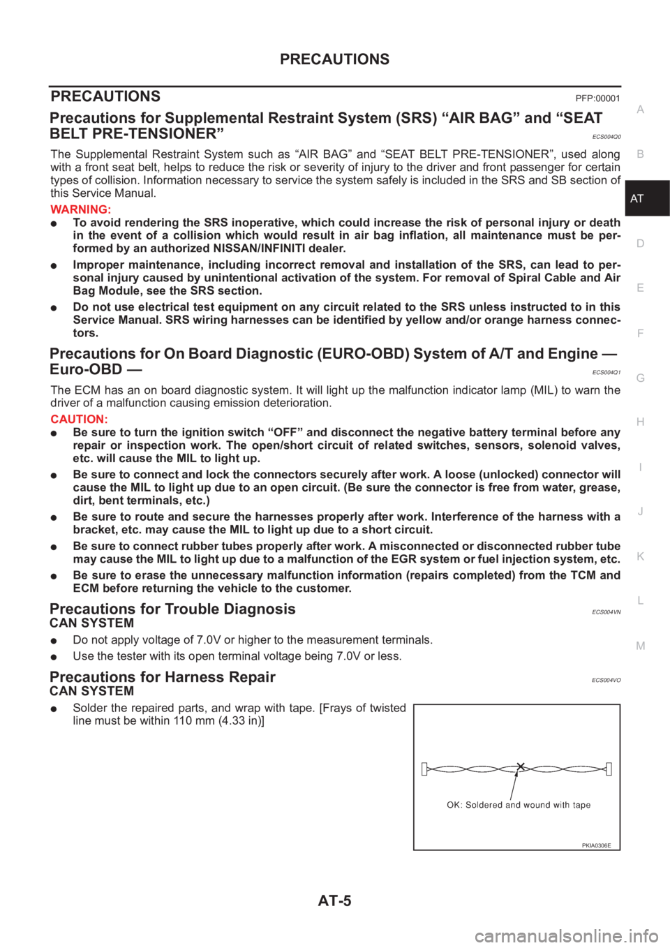
●Solder the repaired parts, and wrap with tape. [Frays of twisted
line must be within 110 mm (4.33 in)]
PKIA0306E
Page 2498 of 3833
![NISSAN X-TRAIL 2001 Service Repair Manual AT-420
[ALL]
REMOVAL AND INSTALLATION
3. Tighten belts fixing transaxle.
4. Reinstall any part removed.
5. Adjust control cable. Refer to AT- 4 1 6 , "
Control Cable Adjust-
ment" .
6. NISSAN X-TRAIL 2001 Service Repair Manual AT-420
[ALL]
REMOVAL AND INSTALLATION
3. Tighten belts fixing transaxle.
4. Reinstall any part removed.
5. Adjust control cable. Refer to AT- 4 1 6 , "
Control Cable Adjust-
ment" .
6.](/manual-img/5/57405/w960_57405-2497.png)
AT-420
[ALL]
REMOVAL AND INSTALLATION
3. Tighten belts fixing transaxle.
4. Reinstall any part removed.
5. Adjust control cable. Refer to AT- 4 1 6 , "
Control Cable Adjust-
ment" .
6. Check continuity of PNP switch. Refer to AT- 11 0 , "
DTC P0705
PARK/NEUTRAL POSITION (PNP) SWITCH" .
7. Refill transaxle with ATF and check fluid level.
8. Move selector lever through all positions to be sure that tran-
saxle operates correctly. With parking brake applied, idle
engine. Move selector lever through “N” to “D”, to “2”, to “1” and
“R” positions. A slight shock should be felt through the hand
gripping the selector each time the transaxle is shifted.
9. Perform road test. Refer to AT-68, "
Road Test" .
Bolt No.Tightening torque
N·m (kg-m, ft-lb)Bolt length “ L ”
mm (in)
1
69.6 - 79.4 (7.1 - 8.1, 51.4 - 58.6)49 (1.93)
2 45 (1.77)
3
39.2 - 46.1 (4.0 - 4.7, 29.0 - 34.0)40 (1.57)
4 30 (1.18)
5
30.4 - 40.2 (3.1 - 4.1, 22.4 - 29.7)40 (1.57)
6 45 (1.97)
SCIA0795E
SAT638A
Page 2741 of 3833
BR-1
BRAKE SYSTEM
F BRAKES
CONTENTS
C
D
E
G
H
I
J
K
L
M
SECTION
A
B
BR
BRAKE SYSTEM
PRECAUTIONS .......................................................... 3
Precautions for Supplemental Restraint System
(SRS) “AIR BAG” and “SEAT BELT PRE-TEN-
SIONER” .................................................................. 3
Precautions for Brake System .................................. 3
PREPARATION ........................................................... 4
Special Service Tools ............................................... 4
Commercial Service Tools ........................................ 4
NOISE, VIBRATION, AND HARSHNESS (NVH)
TROUBLESHOOTING ................................................ 5
NVH Troubleshooting Chart ..................................... 5
BRAKE PEDAL .......................................................... 6
On-Vehicle Inspection and Adjustment .................... 6
Components ............................................................. 7
Removal and Installation .......................................... 7
REMOVAL ............................................................. 7
INSPECTION AFTER REMOVAL ......................... 7
INSTALLATION ..................................................... 8
BRAKE FLUID ............................................................ 9
Checking Brake Fluid Level ..................................... 9
Checking Brake Line ................................................ 9
Changing Brake Fluid ............................................... 9
Brake Burnishing Procedure .................................. 10
Bleeding Brake System .......................................... 10
BRAKE PIPING AND HOSE .....................................11
Hydraulic Piping ...................................................... 11
Removal and Installation of Front Brake Piping and
Brake Hose ............................................................. 11
REMOVAL ............................................................ 11
INSTALLATION .................................................... 11
Removal and Installation of Rear Brake Piping and
Brake Hose ............................................................ 12
REMOVAL ........................................................... 12
INSTALLATION ................................................... 12
Inspection ............................................................... 12
BRAKE MASTER CYLINDER .................................. 13
Components ........................................................... 13
Removal and Installation ........................................ 13
REMOVAL ........................................................... 13INSTALLATION ................................................... 13
Disassembly and Assembly .................................... 14
DISASSEMBLY ................................................... 14
INSPECTION AFTER REMOVAL ....................... 14
ASSEMBLY ......................................................... 15
BRAKE BOOSTER ................................................... 17
On-Vehicle Inspection and Service ......................... 17
FUNCTION INSPECTION ................................... 17
AIRTIGHTNESS INSPECTION ........................... 17
Removal and Installation ........................................ 17
REMOVAL ........................................................... 17
INSPECTION AFTER REMOVAL ....................... 18
INSTALLATION ................................................... 18
VACUUM LINES ....................................................... 19
Removal and Installation ........................................ 19
Inspection ............................................................... 19
VISUAL INSPECTION ......................................... 19
CHECK VALVE INSPECTION ............................. 20
FRONT DISC BRAKE ............................................... 21
Component ............................................................. 21
Inspection ............................................................... 21
PAD THICKNESS ................................................ 21
Pad Replacement ................................................ ... 22
REMOVAL ........................................................... 22
INSTALLATION ................................................... 22
Caliper Removal and Installation ............................ 22
REMOVAL ........................................................... 22
INSTALLATION ................................................... 23
Caliper Disassembly and Assembly ....................... 23
DISASSEMBLY ................................................... 23
INSPECTION AFTER DISASSEMBLY ................ 23
DISC ROTOR INSPECTION ............................... 24
ASSEMBLY ......................................................... 24
BRAKE BURNISHING PROCEDURE ................. 25
REAR DISC BRAKE ................................................. 26
Component ............................................................. 26
Inspection ............................................................... 26
PAD WEAR INSPECTION ................................... 26
Pad Replacement ................................................ ... 27
REMOVAL ........................................................... 27
Page 2743 of 3833
PRECAUTIONS
BR-3
C
D
E
G
H
I
J
K
L
MA
B
BR
PRECAUTIONSPFP:00001
Precautions for Supplemental Restraint System (SRS) “AIR BAG” and “SEAT
BELT PRE-TENSIONER”
EFS002F9
The Supplemental Restraint System such as “AIR BAG” and “SEAT BELT PRE-TENSIONER”, used along
with a front seat belt, helps to reduce the risk or severity of injury to the driver and front passenger for certain
types of collision. Information necessary to service the system safely is included in the SRS and SB section of
this Service Manual.
WARNING:
●To avoid rendering the SRS inoperative, which could increase the risk of personal injury or death
in the event of a collision which would result in air bag inflation, all maintenance must be per-
formed by an authorized NISSAN/INFINITI dealer.
●Improper maintenance, including incorrect removal and installation of the SRS, can lead to per-
sonal injury caused by unintentional activation of the system. For removal of Spiral Cable and Air
Bag Module, see the SRS section.
●Do not use electrical test equipment on any circuit related to the SRS unless instructed to in this
Service Manual. SRS wiring harnesses can be identified by yellow and/or orange harness connec-
tors.
Precautions for Brake SystemEFS000BZ
●Clean dust on brake pads, shoes, drums, and back plates with a vacuum dust collector. Do not blow with
compressed air.
●Recommended fluid is brake fluid “DOT 3” or “DOT 4”.
●Never reuse drained brake fluid.
●Be careful not to splash brake fluid on painted areas such as the body. If brake fluid is splashed or spilled
on paint, wipe it off and flush the area with water immediately.
●Use only clean brake fluid when cleaning master cylinder and disc brake components.
●Never use mineral oils such as gasoline or kerosene to clean. They will ruin the rubber parts and cause
improper operation.
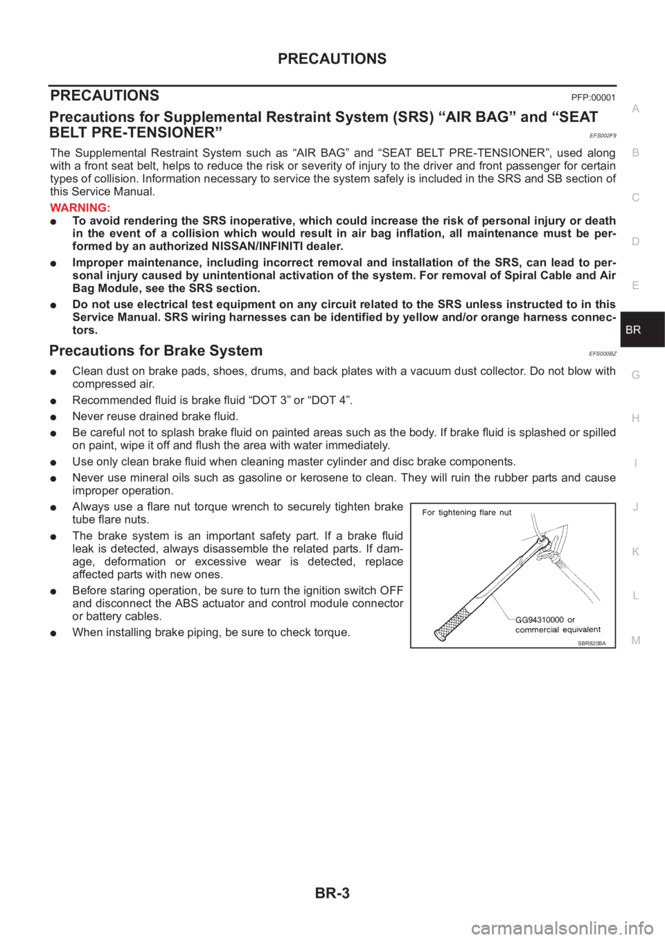
●Always use a flare nut torque wrench to securely tighten brake
tube flare nuts.
●The brake system is an important safety part. If a brake fluid
leak is detected, always disassemble the related parts. If dam-
age, deformation or excessive wear is detected, replace
affected parts with new ones.
●Before staring operation, be sure to turn the ignition switch OFF
and disconnect the ABS actuator and control module connector
or battery cables.
●When installing brake piping, be sure to check torque.SBR820BA
Page 2911 of 3833
PS-1
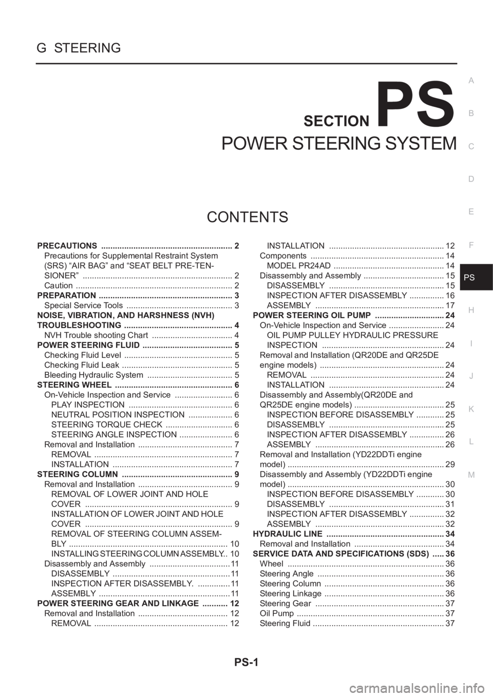
POWER STEERING SYSTEM
G STEERING
CONTENTS
C
D
E
F
H
I
J
K
L
M
SECTION
A
B
PS
POWER STEERING SYSTEM
PRECAUTIONS .......................................................... 2
Precautions for Supplemental Restraint System
(SRS) “AIR BAG” and “SEAT BELT PRE-TEN-
SIONER” .................................................................. 2
Caution ..................................................................... 2
PREPARATION ........................................................... 3
Special Service Tools ............................................... 3
NOISE, VIBRATION, AND HARSHNESS (NVH)
TROUBLESHOOTING ................................................ 4
NVH Trouble shooting Chart .................................... 4
POWER STEERING FLUID ........................................ 5
Checking Fluid Level ........................................... ..... 5
Checking Fluid Leak ............................................ ..... 5
Bleeding Hydraulic System ...................................... 5
STEERING WHEEL .................................................... 6
On-Vehicle Inspection and Service .......................... 6
PLAY INSPECTION .............................................. 6
NEUTRAL POSITION INSPECTION .................... 6
STEERING TORQUE CHECK .............................. 6
STEERING ANGLE INSPECTION ........................ 6
Removal and Installation .......................................... 7
REMOVAL ............................................................. 7
INSTALLATION ..................................................... 7
STEERING COLUMN ................................................. 9
Removal and Installation .......................................... 9
REMOVAL OF LOWER JOINT AND HOLE
COVER ................................................................. 9
INSTALLATION OF LOWER JOINT AND HOLE
COVER ................................................................. 9
REMOVAL OF STEERING COLUMN ASSEM-
BLY ...................................................................... 10
INSTALLING STEERING COLUMN ASSEMBLY ... 10
Disassembly and Assembly .................................... 11
DISASSEMBLY .................................................... 11
INSPECTION AFTER DISASSEMBLY. ............... 11
ASSEMBLY .......................................................... 11
POWER STEERING GEAR AND LINKAGE ............ 12
Removal and Installation ........................................ 12
REMOVAL ........................................................... 12INSTALLATION ................................................... 12
Components ........................................................... 14
MODEL PR24AD ................................................. 14
Disassembly and Assembly .................................... 15
DISASSEMBLY ................................................... 15
INSPECTION AFTER DISASSEMBLY ................ 16
ASSEMBLY ......................................................... 17
POWER STEERING OIL PUMP ............................... 24
On-Vehicle Inspection and Service ......................... 24
OIL PUMP PULLEY HYDRAULIC PRESSURE
INSPECTION ...................................................... 24
Removal and Installation (QR20DE and QR25DE
engine models) ....................................................... 24
REMOVAL ........................................................... 24
INSTALLATION ................................................... 24
Disassembly and Assembly(QR20DE and
QR25DE engine models) ........................................ 25
INSPECTION BEFORE DISASSEMBLY ............. 25
DISASSEMBLY ................................................... 25
INSPECTION AFTER DISASSEMBLY ................ 26
ASSEMBLY ......................................................... 26
Removal and Installation (YD22DDTi engine
model) ..................................................................... 29
Disassembly and Assembly (YD22DDTi engine
model) ..................................................................... 30
INSPECTION BEFORE DISASSEMBLY ............. 30
DISASSEMBLY ................................................... 31
INSPECTION AFTER DISASSEMBLY ................ 32
ASSEMBLY ......................................................... 32
HYDRAULIC LINE .................................................
... 34
Removal and Installation ........................................ 34
SERVICE DATA AND SPECIFICATIONS (SDS) ...... 36
Wheel ..................................................................... 36
Steering Angle ........................................................ 36
Steering Column ..................................................... 36
Steering Linkage ..................................................... 36
Steering Gear ......................................................... 37
Oil Pump ................................................................. 37
Steering Fluid .......................................................... 37
Page 2912 of 3833
PS-2
PRECAUTIONS
PRECAUTIONS
PFP:00001
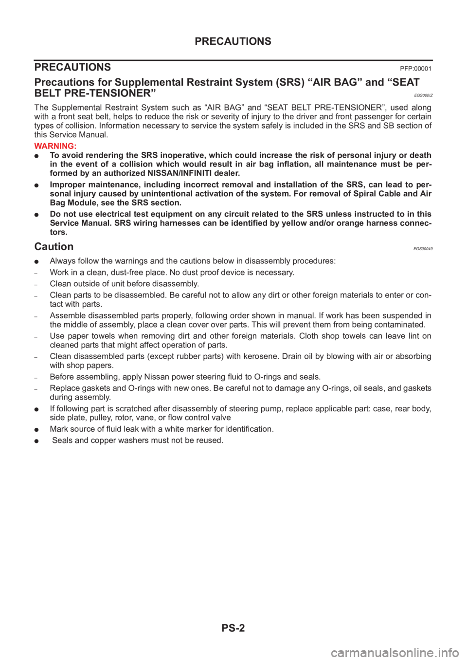
Precautions for Supplemental Restraint System (SRS) “AIR BAG” and “SEAT
BELT PRE-TENSIONER”
EGS000IZ
The Supplemental Restraint System such as “AIR BAG” and “SEAT BELT PRE-TENSIONER”, used along
with a front seat belt, helps to reduce the risk or severity of injury to the driver and front passenger for certain
types of collision. Information necessary to service the system safely is included in the SRS and SB section of
this Service Manual.
WARNING:
●To avoid rendering the SRS inoperative, which could increase the risk of personal injury or death
in the event of a collision which would result in air bag inflation, all maintenance must be per-
formed by an authorized NISSAN/INFINITI dealer.
●Improper maintenance, including incorrect removal and installation of the SRS, can lead to per-
sonal injury caused by unintentional activation of the system. For removal of Spiral Cable and Air
Bag Module, see the SRS section.
●Do not use electrical test equipment on any circuit related to the SRS unless instructed to in this
Service Manual. SRS wiring harnesses can be identified by yellow and/or orange harness connec-
tors.
CautionEGS00049
●Always follow the warnings and the cautions below in disassembly procedures:
–Work in a clean, dust-free place. No dust proof device is necessary.
–Clean outside of unit before disassembly.
–Clean parts to be disassembled. Be careful not to allow any dirt or other foreign materials to enter or con-
tact with parts.
–Assemble disassembled parts properly, following order shown in manual. If work has been suspended in
the middle of assembly, place a clean cover over parts. This will prevent them from being contaminated.
–Use paper towels when removing dirt and other foreign materials. Cloth shop towels can leave lint on
cleaned parts that might affect operation of parts.
–Clean disassembled parts (except rubber parts) with kerosene. Drain oil by blowing with air or absorbing
with shop papers.
–Before assembling, apply Nissan power steering fluid to O-rings and seals.
–Replace gaskets and O-rings with new ones. Be careful not to damage any O-rings, oil seals, and gaskets
during assembly.
●If following part is scratched after disassembly of steering pump, replace applicable part: case, rear body,
side plate, pulley, rotor, vane, or flow control valve
●Mark source of fluid leak with a white marker for identification.
● Seals and copper washers must not be reused.
Page 2914 of 3833
PS-4
NOISE, VIBRATION, AND HARSHNESS (NVH) TROUBLESHOOTING
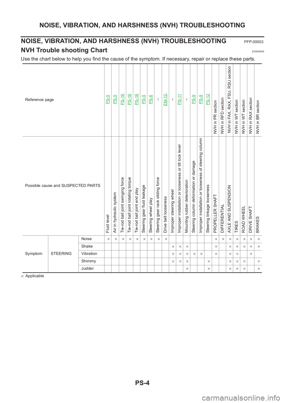
NOISE, VIBRATION, AND HARSHNESS (NVH) TROUBLESHOOTING
PFP:00003
NVH Trouble shooting ChartEGS000A9
Use the chart below to help you find the cause of the symptom. If necessary, repair or replace these parts.
×: ApplicableReference page
PS-5PS-5PS-16PS-16PS-16PS-5PS-6–
EM-12
.
–
PS-11
–
PS-9PS-9PS-12
NVH in PR section
NVH in RFD section
NVH in FAX, RAX, FSU, RSU section
NVH in WT section
NVH in WT section
NVH in RAX section
NVH in BR section
Possible cause and SUSPECTED PARTS
Fluid level
Air in hydraulic system
Tie-rod ball joint swinging force
Tie-rod ball joint rotating torque
Tie-rod ball joint end play
Steering gear fluid leakage
Steering wheel play
Steering gear rack sliding force
Drive belt looseness
Improper steering wheel
Improper installation or looseness or tilt lock lever
Mounting rubber deterioration
Steering column deformation or damage
Improper installation or looseness of steering column
Steering linkage looseness
PROPELLER SHAFT
DIFFERENTIAL
AXLE AND SUSPENSION
TIRES
ROAD WHEEL
DRIVE SHAFT
BRAKES
Symptom STEERINGNoise× × ××××× × × ×××××× ×
Shake××× × ×××× ×
Vibration××××× × ×× ×
Shimmy××× × ××× ×
Judder× × ××× ×