Page 2693 of 3833
REAR FINAL DRIVE ASSEMBLY
RFD-17
C
E
F
G
H
I
J
K
L
MA
B
RFD
COMPANION FLANGE RUNOUT
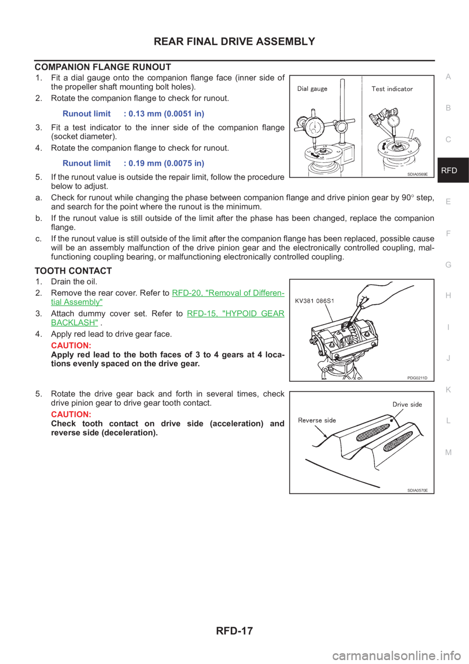
1. Fit a dial gauge onto the companion flange face (inner side of
the propeller shaft mounting bolt holes).
2. Rotate the companion flange to check for runout.
3. Fit a test indicator to the inner side of the companion flange
(socket diameter).
4. Rotate the companion flange to check for runout.
5. If the runout value is outside the repair limit, follow the procedure
below to adjust.
a. Check for runout while changing the phase between companion flange and drive pinion gear by 90° step,
and search for the point where the runout is the minimum.
b. If the runout value is still outside of the limit after the phase has been changed, replace the companion
flange.
c. If the runout value is still outside of the limit after the companion flange has been replaced, possible cause
will be an assembly malfunction of the drive pinion gear and the electronically controlled coupling, mal-
functioning coupling bearing, or malfunctioning electronically controlled coupling.
TOOTH CONTACT
1. Drain the oil.
2. Remove the rear cover. Refer to RFD-20, "
Removal of Differen-
tial Assembly"
3. Attach dummy cover set. Refer to RFD-15, "HYPOID GEAR
BACKLASH" .
4. Apply red lead to drive gear face.
CAUTION:
Apply red lead to the both faces of 3 to 4 gears at 4 loca-
tions evenly spaced on the drive gear.
5. Rotate the drive gear back and forth in several times, check
drive pinion gear to drive gear tooth contact.
CAUTION:
Check tooth contact on drive side (acceleration) and
reverse side (deceleration).Runout limit : 0.13 mm (0.0051 in)
Runout limit : 0.19 mm (0.0075 in)
SDIA0569E
PDG0211D
SDIA0570E
Page 2751 of 3833
BRAKE PIPING AND HOSE
BR-11
C
D
E
G
H
I
J
K
L
MA
B
BR
BRAKE PIPING AND HOSEPFP:46210
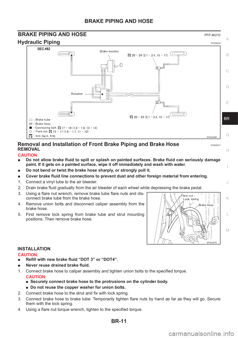
Hydraulic Piping EFS000C6
Removal and Installation of Front Brake Piping and Brake HoseEFS000C7
REMOVAL
CAUTION:
●Do not allow brake fluid to spill or splash on painted surfaces. Brake fluid can seriously damage
paint. If it gets on a painted surface, wipe it off immediately and wash with water.
●Do not bend or twist the brake hose sharply, or strongly pull it.
●Cover brake fluid line connections to prevent dust and other foreign material from entering.
1. Connect a vinyl tube to the air bleeder.
2. Drain brake fluid gradually from the air bleeder of each wheel while depressing the brake pedal.
3. Using a flare nut wrench, remove brake tube flare nuts and dis-
connect brake tube from the brake hose.
4. Remove union bolts and disconnect caliper assembly from the
brake hose.
5. First remove lock spring from brake tube and strut mounting
positions. Then remove brake hose.
INSTALLATION
CAUTION:
●Refill with new brake fluid “DOT 3” or “DOT4”.
●Never reuse drained brake fluid.
1. Connect brake hose to caliper assembly and tighten union bolts to the specified torque.
CAUTION:
●Securely connect brake hose to the protrusions on the cylinder body.
●Do not reuse the copper washer for union bolts.
2. Connect brake hose to the strut and fix with lock spring.
3. Connect brake hose to brake tube. Temporarily tighten flare nuts by hand as far as they will go. Secure
them with the lock spring.
4. Using a flare nut torque wrench, tighten to the specified torque.
SFIA0346E
SFIA0347E
Page 2762 of 3833
BR-22
FRONT DISC BRAKE
Pad Replacement
EFS000CI
REMOVAL
CAUTION:
When replacing brake pads, always replace inner shims, outer shims, and shim covers as a set.
1. Remove master cylinder reservoir tank cap.
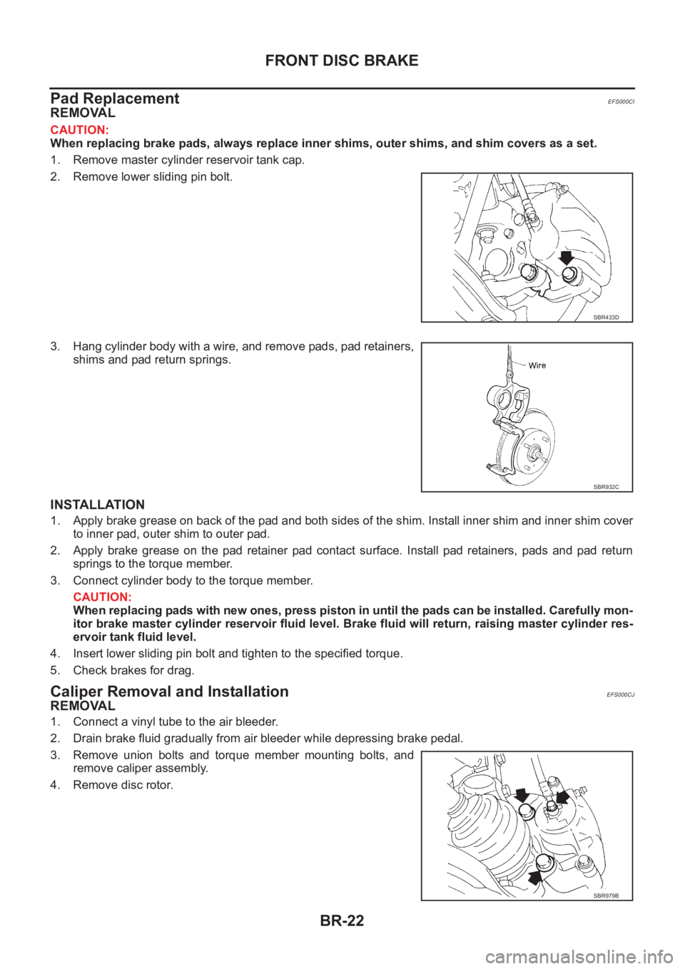
2. Remove lower sliding pin bolt.
3. Hang cylinder body with a wire, and remove pads, pad retainers,
shims and pad return springs.
INSTALLATION
1. Apply brake grease on back of the pad and both sides of the shim. Install inner shim and inner shim cover
to inner pad, outer shim to outer pad.
2. Apply brake grease on the pad retainer pad contact surface. Install pad retainers, pads and pad return
springs to the torque member.
3. Connect cylinder body to the torque member.
CAUTION:
When replacing pads with new ones, press piston in until the pads can be installed. Carefully mon-
itor brake master cylinder reservoir fluid level. Brake fluid will return, raising master cylinder res-
ervoir tank fluid level.
4. Insert lower sliding pin bolt and tighten to the specified torque.
5. Check brakes for drag.
Caliper Removal and InstallationEFS000CJ
REMOVAL
1. Connect a vinyl tube to the air bleeder.
2. Drain brake fluid gradually from air bleeder while depressing brake pedal.
3. Remove union bolts and torque member mounting bolts, and
remove caliper assembly.
4. Remove disc rotor.
SBR433D
SBR932C
SBR979B
Page 2763 of 3833
FRONT DISC BRAKE
BR-23
C
D
E
G
H
I
J
K
L
MA
B
BR
INSTALLATION
CAUTION:
●Refill with new brake fluid “DOT 3” or “DOT 4”.
●Never reuse drained brake fluid.
1. Install disc rotor.
2. Install caliper assembly. Tighten mounting bolts to the specified torque.
CAUTION:
Before installing caliper assembly, wipe oil and grease on steering knuckle washer seats and cali-
per assembly mounting surface.
3. Connect brake hose to caliper assembly and tighten union bolts to the specified torque.
CAUTION:
●Do not reuse the copper washer for union bolts.
●Securely assemble brake hose to protrusions on cylinder body.
4. Bleed air. Refer to BR-10, "
Bleeding Brake System" .
Caliper Disassembly and Assembly EFS000CK
DISASSEMBLY
WARNING:
Be careful not to pinch your fingers in the piston.
CAUTION:
Be careful not to damage the cylinder inner wall.
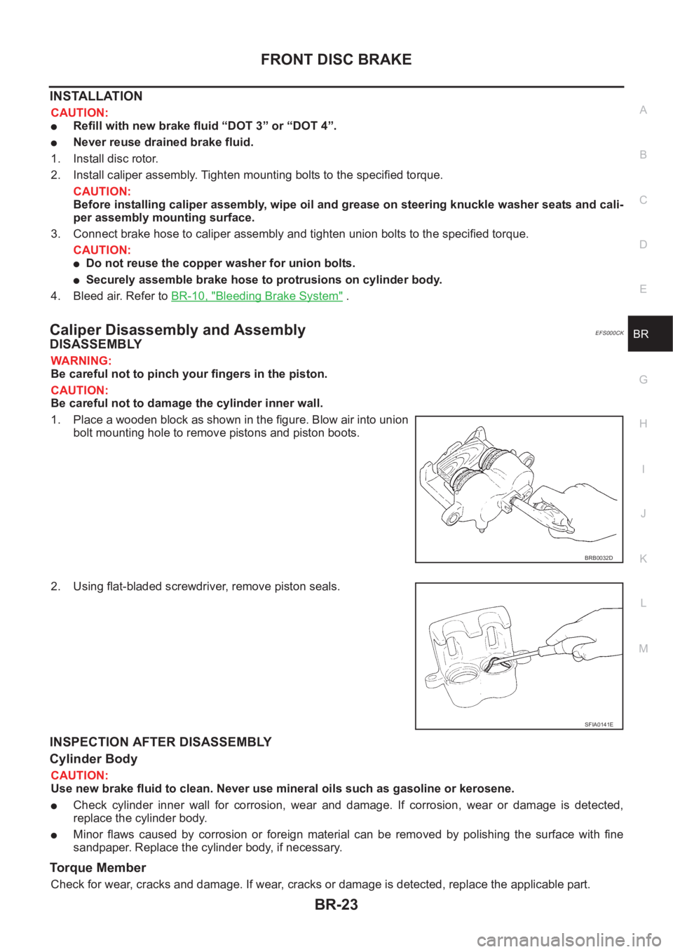
1. Place a wooden block as shown in the figure. Blow air into union
bolt mounting hole to remove pistons and piston boots.
2. Using flat-bladed screwdriver, remove piston seals.
INSPECTION AFTER DISASSEMBLY
Cylinder Body
CAUTION:
Use new brake fluid to clean. Never use mineral oils such as gasoline or kerosene.
●Check cylinder inner wall for corrosion, wear and damage. If corrosion, wear or damage is detected,
replace the cylinder body.
●Minor flaws caused by corrosion or foreign material can be removed by polishing the surface with fine
sandpaper. Replace the cylinder body, if necessary.
Torque Member
Check for wear, cracks and damage. If wear, cracks or damage is detected, replace the applicable part.
BRB0032D
SFIA0141E
Page 2768 of 3833
BR-28
REAR DISC BRAKE
Caliper Removal and Installation
EFS00180
REMOVAL
1. Connect a vinyl tube to the air bleeder.
2. Drain brake fluid gradually from air bleeder while depressing
brake pedal.
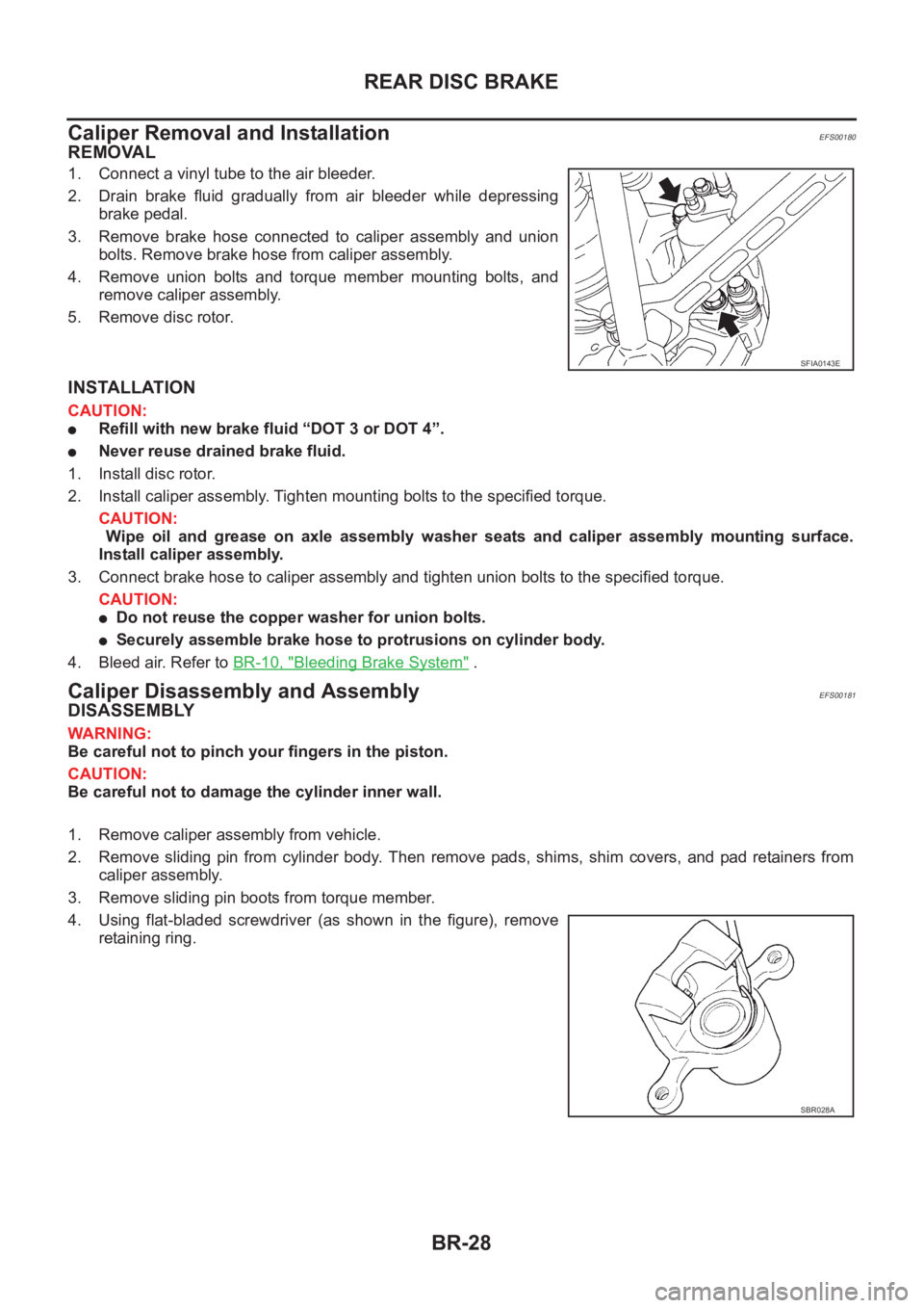
3. Remove brake hose connected to caliper assembly and union
bolts. Remove brake hose from caliper assembly.
4. Remove union bolts and torque member mounting bolts, and
remove caliper assembly.
5. Remove disc rotor.
INSTALLATION
CAUTION:
●Refill with new brake fluid “DOT 3 or DOT 4”.
●Never reuse drained brake fluid.
1. Install disc rotor.
2. Install caliper assembly. Tighten mounting bolts to the specified torque.
CAUTION:
Wipe oil and grease on axle assembly washer seats and caliper assembly mounting surface.
Install caliper assembly.
3. Connect brake hose to caliper assembly and tighten union bolts to the specified torque.
CAUTION:
●Do not reuse the copper washer for union bolts.
●Securely assemble brake hose to protrusions on cylinder body.
4. Bleed air. Refer to BR-10, "
Bleeding Brake System" .
Caliper Disassembly and AssemblyEFS00181
DISASSEMBLY
WARNING:
Be careful not to pinch your fingers in the piston.
CAUTION:
Be careful not to damage the cylinder inner wall.
1. Remove caliper assembly from vehicle.
2. Remove sliding pin from cylinder body. Then remove pads, shims, shim covers, and pad retainers from
caliper assembly.
3. Remove sliding pin boots from torque member.
4. Using flat-bladed screwdriver (as shown in the figure), remove
retaining ring.
SFIA0143E
SBR028A
Page 3217 of 3833
SUNROOF
RF-9
C
D
E
F
G
H
J
K
L
MA
B
RF
SUNROOF UNIT
Removal
CAUTION:
●Removal and installation of sunroof unit require 2 workers.
●When taking sunroof unit out, use shop cloths to protect seats and trim from damage.
●After installing sunroof unit and glass lid, be sure to carry out the leak test to confirm there is no
more leakage.
1. Remove headlining. Refer to EI-29, "
HEADLINING"
2. Disconnect drain hoses.
3. Disconnect interior lamp harness.
4. Remove both unit-side and body-side front bracket mounting
bolts.
5. Remove both unit-side and body-side center and rear bracket
mounting bolts.
6. Remove motor bracket mounting bolt.
7. Remove mounting bolts on the front end and side rails, and
remove sunroof unit from the roof panel.
8. Remove the sunroof unit out of the passenger compartment
while being careful not to damage the seats and trim.
SIIA0130E
SIIA0184E
SIIA0121E
SIIA0183E
Page 3218 of 3833
RF-10
SUNROOF
Installation
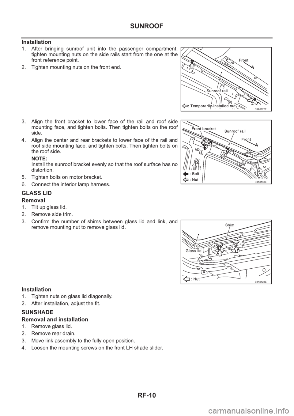
1. After bringing sunroof unit into the passenger compartment,
tighten mounting nuts on the side rails start from the one at the
front reference point.
2. Tighten mounting nuts on the front end.
3. Align the front bracket to lower face of the rail and roof side
mounting face, and tighten bolts. Then tighten bolts on the roof
side.
4. Align the center and rear brackets to lower face of the rail and
roof side mounting face, and tighten bolts. Then tighten bolts on
the roof side.
NOTE:
Install the sunroof bracket evenly so that the roof surface has no
distortion.
5. Tighten bolts on motor bracket.
6. Connect the interior lamp harness.
GLASS LID
Removal
1. Tilt up glass lid.
2. Remove side trim.
3. Confirm the number of shims between glass lid and link, and
remove mounting nut to remove glass lid.
Installation
1. Tighten nuts on glass lid diagonally.
2. After installation, adjust the fit.
SUNSHADE
Removal and installation
1. Remove glass lid.
2. Remove rear drain.
3. Move link assembly to the fully open position.
4. Loosen the mounting screws on the front LH shade slider.
SIIA0122E
SIIA0131E
SIIA0124E
Page 3398 of 3833
ATC-122
HEATER & COOLING UNIT ASSEMBLY
HEATER & COOLING UNIT ASSEMBLY
PFP:27110
Removal and InstallationEJS000UT
REMOVAL
1. Discharge refrigerant from A/C system.
2. Drain coolant from cooling system. Refer to CO-9, "
Changing
Engine Coolant" for QR engine, CO-29, "Changing Engine
Coolant" for YD engine.
3. Disconnect two heater hoses from heater core pipe.
4. Remove the instrument panel.
5. Remove the blower unit.
6. Remove clips of vehicle harness from steering member.
7. Remove the instrument stay.
8. Remove the bolts from heater & cooling unit.
9. Remove the steering member.
10. Remove the heater & cooling unit.
RJIA0060E
RJIA0061E
RJIA0062E
RJIA0063E