Page 305 of 3833
![NISSAN X-TRAIL 2001 Service Repair Manual OIL COOLER
LU-25
[YD22DDTi]
C
D
E
F
G
H
I
J
K
L
MA
LU
OIL COOLERPFP:21305
Removal and InstallationEBS00OE8
CAUTION:
●Be careful not to get burned when the engine and engine oil are hot.
●When remo NISSAN X-TRAIL 2001 Service Repair Manual OIL COOLER
LU-25
[YD22DDTi]
C
D
E
F
G
H
I
J
K
L
MA
LU
OIL COOLERPFP:21305
Removal and InstallationEBS00OE8
CAUTION:
●Be careful not to get burned when the engine and engine oil are hot.
●When remo](/manual-img/5/57405/w960_57405-304.png)
OIL COOLER
LU-25
[YD22DDTi]
C
D
E
F
G
H
I
J
K
L
MA
LU
OIL COOLERPFP:21305
Removal and InstallationEBS00OE8
CAUTION:
●Be careful not to get burned when the engine and engine oil are hot.
●When removing, prepare a shop cloth to absorb any engine oil leakage or spillage.
●Completely wipe off any engine oil that adhere to the engine and the vehicle.
REMOVAL
1. Remove front RH wheel and engine side cover.
2. Remove the exhaust front tube. Refer to EX-2, "
EXHAUST SYSTEM" .
3. Drain coolant by removing cylinder block drain plug and radiator drain cock.
INSPECTION
Oil Cooler
Check oil cooler for cracks. check oil cooler for clogging by blowing through coolant inlet. If necessary, replace
oil cooler assembly.
INSTALLATION
Installation is in reverse order of removal.
●Confirm that no foreign objects are adhering to the installation
planes of the oil cooler or cylinder block.
●Tighten the connecting bolt after aligning the stopper on the cyl-
inder block side with protrusion of the oil cooler.
●After for warming up the engine, check for engine oil and engine
coolant leakage and for engine oil level. Refer to LU-18,
"ENGINE OIL" .
PBIC1231E
1. Oil cooler 2. O-ring 3. Water hose
4. Gasket 5. Water hose connector 6. Connecting bolt
SBIA0126E
Page 306 of 3833
![NISSAN X-TRAIL 2001 Service Repair Manual LU-26
[YD22DDTi]
SERVICE DATA AND SPECIFICATIONS (SDS)
SERVICE DATA AND SPECIFICATIONS (SDS)
PFP:00030
Standard and LimitEBS00CTZ
OIL PRESSURE
OIL PUMP
Unit: mm (in)
REGULATOR VALVE
Unit: mm (in)
OIL NISSAN X-TRAIL 2001 Service Repair Manual LU-26
[YD22DDTi]
SERVICE DATA AND SPECIFICATIONS (SDS)
SERVICE DATA AND SPECIFICATIONS (SDS)
PFP:00030
Standard and LimitEBS00CTZ
OIL PRESSURE
OIL PUMP
Unit: mm (in)
REGULATOR VALVE
Unit: mm (in)
OIL](/manual-img/5/57405/w960_57405-305.png)
LU-26
[YD22DDTi]
SERVICE DATA AND SPECIFICATIONS (SDS)
SERVICE DATA AND SPECIFICATIONS (SDS)
PFP:00030
Standard and LimitEBS00CTZ
OIL PRESSURE
OIL PUMP
Unit: mm (in)
REGULATOR VALVE
Unit: mm (in)
OIL CAPACITY
Unit: · (Imp qt)
Tightening TorqueEBS00B0F
Unit: N·m (kg-m, ft-lb)
Unit: N·m (kg-m, in-lb)* Engine speed rpm
Approximate discharge pressure kPa (bar, kg/cm
2 , psi)
Idle speed
2,000
4,000 More than 140 (1.40, 1.43, 20.3)
More than 270 (2.69, 2.75, 39.1)
More than 430 (4.29, 4.38, 62.3)
Body to outer rotor radial clearance 0.114 - 0.260 (0.0045 - 0.0102)
Inner rotor to outer rotor tip clearance Below 0.18 (0.0071)
Body to inner rotor axial clearance 0.050 - 0.090 (0.0020 - 0.0035)
Body to outer rotor axial clearance 0.030 - 0.190 (0.0012 - 0.0075)
Inner rotor to brazed portion of housing clearance 0.045 - 0.091 (0.0018 - 0.0036)
Regulator valve to oil pump cover clearance 0.040 - 0.097 (0.0016 - 0.0038)
With oil filter change Approximately 5.2 (4-5/8 Imp qt)
Without oil filter change Approximately 4.9 (4-3/8 Imp qt)
Dry engine (engine overhaul) Approximately 6.3 (5-1/2 Imp qt)
Oil pressure switch 13 - 17 (1.4 - 1.7, 10 - 12)
Oil pan drain plug 29 - 39 (3.0 - 4.0, 22 - 29)
Oil filter bracket20 -23 (2.0 - 2.4, 15 - 17)
Oil filter body20 - 24 (2.0 - 2.5, 15 - 18)
Oil pump assembly 6.4 - 7.4 (0.65 - 0.76, 57 - 65)*
Oil pump cover 5.9 - 7.8 (0.6 - 0.8, 52 - 69)*
Regulator plug40 - 68 (4.0 - 7.0, 29 - 50)
Water hose connector for oil cooler 25 - 31 (2.5 - 3.2, 18 - 23)
Connecting bolt20 - 29 (2.1 - 2.9, 15 - 21)
Page 324 of 3833
![NISSAN X-TRAIL 2001 Service Repair Manual CO-18
[QR]
WATER PUMP
WATE R P U M P
PFP:21020
Removal and InstallationEBS00KON
WARNING:
Never remove the radiator cap when the engine is hot. Serious burns could occur from high pressure
engine cool NISSAN X-TRAIL 2001 Service Repair Manual CO-18
[QR]
WATER PUMP
WATE R P U M P
PFP:21020
Removal and InstallationEBS00KON
WARNING:
Never remove the radiator cap when the engine is hot. Serious burns could occur from high pressure
engine cool](/manual-img/5/57405/w960_57405-323.png)
CO-18
[QR]
WATER PUMP
WATE R P U M P
PFP:21020
Removal and InstallationEBS00KON
WARNING:
Never remove the radiator cap when the engine is hot. Serious burns could occur from high pressure
engine coolant escaping from the radiator.
REMOVAL
Water Pump Removal
1. Drain engine coolant. Refer to CO-9, "DRAINING ENGINE COOLANT" .
CAUTION:
Perform when the engine is cold.
2. Remove the following parts.
●Engine undercover
●Alternator, water pump and air compressor belt. Refer to EM-12, "DRIVE BELTS" .
3. Remove water pump.
●Engine coolant will leak from the cylinder block, so have a receptacle ready below.
CAUTION:
●Handle the water pump vane so that it does not contact any other parts.
●Water pump cannot be disassembled and should be replaced as a unit.
Water Pump Housing Removal
1. Perform step 1 and 2 of “Water Pump Removal”.
2. Remove alternator.
3. Remove oil level gauge.
CAUTION:
Plug the oil level gauge guide opening to prevent oil pan from entering foreign materials.
4. Remove bolts mounting water pipe.
5. Remove water pump housing.
Water Pipe Removal
1. Remove water pump housing.
2. Remove exhaust manifold and three way catalyst assembly. Refer to EM-24, "
EXHAUST MANIFOLD
AND THREE WAY CATALYST" .
KBIA0154E
1. Water pump 2. Gasket 3. Water pump housing
4. Water pipe
Page 345 of 3833
![NISSAN X-TRAIL 2001 Service Repair Manual WATER PUMP
CO-39
[YD22DDTi]
C
D
E
F
G
H
I
J
K
L
MA
CO
WAT E R P U MPPFP:21020
Removal and InstallationEBS00BB4
WARNING:
Never remove the radiator cap when the engine is hot. Serious burns could occur NISSAN X-TRAIL 2001 Service Repair Manual WATER PUMP
CO-39
[YD22DDTi]
C
D
E
F
G
H
I
J
K
L
MA
CO
WAT E R P U MPPFP:21020
Removal and InstallationEBS00BB4
WARNING:
Never remove the radiator cap when the engine is hot. Serious burns could occur](/manual-img/5/57405/w960_57405-344.png)
WATER PUMP
CO-39
[YD22DDTi]
C
D
E
F
G
H
I
J
K
L
MA
CO
WAT E R P U MPPFP:21020
Removal and InstallationEBS00BB4
WARNING:
Never remove the radiator cap when the engine is hot. Serious burns could occur from high pressure
engine coolant escaping from the radiator.
REMOVAL
1. Remove the under cover, splash cover (right), and drive belt.
2. Drain engine coolant. Refer to CO-29, "
DRAINING ENGINE COOLANT" .
CAUTION:
Perform when the engine is cold.
3. Support the bottom of the oil pan with a floor jack etc, and remove the right engine mount bracket (front
side of the engine).
4. Remove the water pump pulley.
●Loosen the pulley bolts after fixing the pulley using a screwdriver etc.
5. Remove engine mount bracket.
6. Remove the water pump.
●Engine coolant will leak from the cylinder block, so have a receptacle ready below.
CAUTION:
●Handle the water pump vane so that it does not contact any other parts.
●Water pump cannot be disassembled and should be replaced as a unit.
INSPECTION AFTER REMOVAL
●Visually check that there is no significant dirt or rusting on the
water pump body and vane.
●Check that there is no looseness in the vane shaft, and that it
turns smoothly when rotated by hand.
●If there are any unusualness, replace the water pump assembly.
JLC294B
SBIA0132E
Page 1969 of 3833

OPERATING CYLINDER
CL-11
D
E
F
G
H
I
J
K
L
MA
B
CL
OPERATING CYLINDERPFP:30620
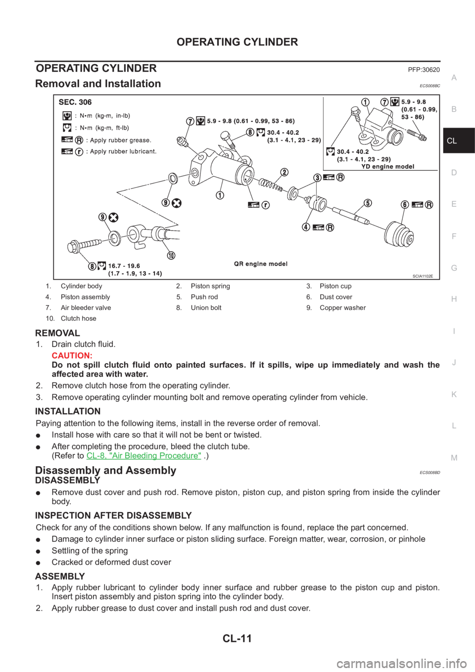
Removal and InstallationECS008BC
REMOVAL
1. Drain clutch fluid.
CAUTION:
Do not spill clutch fluid onto painted surfaces. If it spills, wipe up immediately and wash the
affected area with water.
2. Remove clutch hose from the operating cylinder.
3. Remove operating cylinder mounting bolt and remove operating cylinder from vehicle.
INSTALLATION
Paying attention to the following items, install in the reverse order of removal.
●Install hose with care so that it will not be bent or twisted.
●After completing the procedure, bleed the clutch tube.
(Refer to CL-8, "
Air Bleeding Procedure" .)
Disassembly and AssemblyECS008BD
DISASSEMBLY
●Remove dust cover and push rod. Remove piston, piston cup, and piston spring from inside the cylinder
body.
INSPECTION AFTER DISASSEMBLY
Check for any of the conditions shown below. If any malfunction is found, replace the part concerned.
●Damage to cylinder inner surface or piston sliding surface. Foreign matter, wear, corrosion, or pinhole
●Settling of the spring
●Cracked or deformed dust cover
ASSEMBLY
1. Apply rubber lubricant to cylinder body inner surface and rubber grease to the piston cup and piston.
Insert piston assembly and piston spring into the cylinder body.
2. Apply rubber grease to dust cover and install push rod and dust cover.
1. Cylinder body 2. Piston spring 3. Piston cup
4. Piston assembly 5. Push rod 6. Dust cover
7. Air bleeder valve 8. Union bolt 9. Copper washer
10. Clutch hose
SCIA1102E
Page 1979 of 3833
PRECAUTIONS
MT-3
D
E
F
G
H
I
J
K
L
MA
B
MT
PRECAUTIONSPFP:00001
CautionECS008BM
●Do not reuse transaxle oil, once it has been drained.
●Check oil level or replace oil with vehicle on level ground.
●During removal or installation, keep inside of transaxle clear of dust or dirt.
●Check for the correct installation status prior to removal or disassembly. If mating marks are required, be
certain they do not interfere with the function of the parts they are applied to.
●In principle, tighten bolts or nuts gradually in several steps working diagonally from inside to outside. If
tightening sequence is specified, observe it.
●Be careful not to damage sliding surfaces and mating surfaces.
Page 1991 of 3833

TRANSAXLE ASSEMBLY
MT-15
D
E
F
G
H
I
J
K
L
MA
B
MT
TRANSAXLE ASSEMBLYPFP:32010
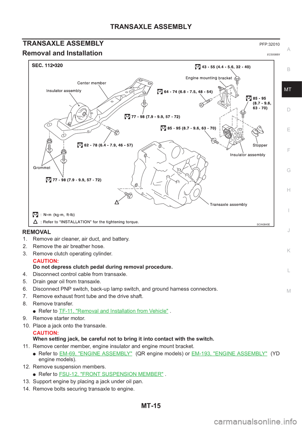
Removal and InstallationECS008BX
REMOVAL
1. Remove air cleaner, air duct, and battery.
2. Remove the air breather hose.
3. Remove clutch operating cylinder.
CAUTION:
Do not depress clutch pedal during removal procedure.
4. Disconnect control cable from transaxle.
5. Drain gear oil from transaxle.
6. Disconnect PNP switch, back-up lamp switch, and ground harness connectors.
7. Remove exhaust front tube and the drive shaft.
8. Remove transfer.
●Refer to TF-11, "Removal and Installation from Vehicle" .
9. Remove starter motor.
10. Place a jack onto the transaxle.
CAUTION:
When setting jack, be careful not to bring it into contact with the switch.
11. Remove center member, engine insulator and engine mount bracket.
●Refer to EM-69, "ENGINE ASSEMBLY" (QR engine models) or EM-193, "ENGINE ASSEMBLY" (YD
engine models).
12. Remove suspension members.
●Refer to FSU-12, "FRONT SUSPENSION MEMBER" .
13. Support engine by placing a jack under oil pan.
14. Remove bolts securing transaxle to engine.
SCIA0845E
Page 2002 of 3833
MT-26
TRANSAXLE ASSEMBLY
FINAL DRIVE COMPONENTS
Disassembly and Assembly (RS5F51A)ECS008C0
DISASSEMBLY
1. Remove drain plug and filler plug.
2. Remove park/neutral position switch and back-up lamp switch.
3. After removing shift check and stopper bolt, remove control
assembly.
1. Differential side bearing outer race 2. Differential side bearing 3. Differential case
4. Final gear 5. Differential side bearing 6. Differential side bearing outer race
7. Differential side bearing adjusting shim 8. Pinion mate shaft 9.Side gear
10. Side gear thrust washer 11. Pinion mate gear 12. Pinion mate gear washer
13. Retaining pin
SCIA0388E
SCIA0389E