2001 NISSAN X-TRAIL engine coolant
[x] Cancel search: engine coolantPage 1901 of 3833
![NISSAN X-TRAIL 2001 Service Repair Manual EGR VOLUME CONTROL SYSTEM
EC-1551
[YD]
C
D
E
F
G
H
I
J
K
L
MA
EC
EGR VOLUME CONTROL SYSTEMPFP:14710
DescriptionEBS0035N
SYSTEM DESCRIPTION
This system controls flow rate of EGR led from exhaust manifo NISSAN X-TRAIL 2001 Service Repair Manual EGR VOLUME CONTROL SYSTEM
EC-1551
[YD]
C
D
E
F
G
H
I
J
K
L
MA
EC
EGR VOLUME CONTROL SYSTEMPFP:14710
DescriptionEBS0035N
SYSTEM DESCRIPTION
This system controls flow rate of EGR led from exhaust manifo](/manual-img/5/57405/w960_57405-1900.png)
EGR VOLUME CONTROL SYSTEM
EC-1551
[YD]
C
D
E
F
G
H
I
J
K
L
MA
EC
EGR VOLUME CONTROL SYSTEMPFP:14710
DescriptionEBS0035N
SYSTEM DESCRIPTION
This system controls flow rate of EGR led from exhaust manifold to intake manifold. The opening of the EGR
by-pass passage in the EGR volume control valve changes to control the flow rate. A built-in step motor
moves the valve in steps corresponding to the ECM output pulses. The opening of the valve varies for opti-
mum engine control. The optimum value stored in the ECM is determined by considering various engine con-
ditions.
The EGR volume control valve remains close under the following conditions.
●Engine stopped
●Engine starting
●Low engine coolant temperature
●Excessively high engine coolant temperature
●High engine speed
●Wide open throttle
COMPONENT DESCRIPTION
EGR Volume Control Valve
The EGR volume control valve uses a step motor to control the flow
rate of EGR from exhaust manifold. This motor has four winding
phases. It operates according to the output pulse signal of the ECM.
Two windings are turned ON and OFF in sequence. Each time an
ON pulse is issued, the valve opens or closes, changing the flow
rate. When no change in the flow rate is needed, the ECM does not
issue the pulse signal. A certain voltage signal is issued so that the
valve remains at that particular opening.
CONSULT-II Reference Value in Data Monitor ModeEBS0035O
Specification data are reference values.
Sensor Input Signal to ECM ECM Function Actuator
Crankshaft position sensor (TDC) Engine speed
EGR volume con-
trolEGR volume control
valve Vehicle speed sensor Vehicle speed
Engine coolant temperature sensor Engine coolant temperature
Ignition switch Start signal
Accelerator pedal position sensor Accelerator pedal position
Mass air flow sensor Amount of intake air
Air conditioner switch Air conditioner operation
SEF908Y
SEF411Y
Page 1924 of 3833
![NISSAN X-TRAIL 2001 Service Repair Manual EC-1574
[YD]
SERVICE DATA AND SPECIFICATIONS (SDS)
SERVICE DATA AND SPECIFICATIONS (SDS)
PFP:00100
General SpecificationsEBS00361
Mass Air Flow SensorEBS00CU1
Engine Coolant Temperature SensorEBS00363 NISSAN X-TRAIL 2001 Service Repair Manual EC-1574
[YD]
SERVICE DATA AND SPECIFICATIONS (SDS)
SERVICE DATA AND SPECIFICATIONS (SDS)
PFP:00100
General SpecificationsEBS00361
Mass Air Flow SensorEBS00CU1
Engine Coolant Temperature SensorEBS00363](/manual-img/5/57405/w960_57405-1923.png)
EC-1574
[YD]
SERVICE DATA AND SPECIFICATIONS (SDS)
SERVICE DATA AND SPECIFICATIONS (SDS)
PFP:00100
General SpecificationsEBS00361
Mass Air Flow SensorEBS00CU1
Engine Coolant Temperature SensorEBS00363
Common Rail Fuel Pressure SensorEBS00BLQ
Crankshaft Position Sensor (TDC)EBS00BLS
Camshaft Position SensorEBS00364
Glow PlugEBS00365
EGR Volume Control ValveEBS00367
EngineYD22DDTi
Idle speed725± 25 rpm
Maximum engine speed 4,800 rpm
Supply voltageBattery voltage (11 - 14V)
Ignition switch "ON" (Engine stopped.) Approx. 1.0V
Idle (Engine is warmed up to normal operating temperature.) 1.0 - 2.5V
2,000 rpm (Engine is warmed up to normal operating tempera-
ture.)2.1 - 2.7V
Temperature °C (°F) Resistance kΩ
20 (68) 2.1 - 2.9
50 (122) 0.68 - 1.00
90 (194) 0.236 - 0.260
Supply voltageApproximately 5V
Idle (Engine is warmed up to normal operating temperature.) 1.6 - 1.8V
2,000 rpm (Engine is warmed up to normal operating tempera-
ture.)1.8 - 2.0V
Resistance [at 20°C (68°F)] Ω1,850 - 2,450
Resistance [at 20°C (68°F)] Ω1,850 - 2,450
Resistance [at 25°C (77°F)] Ω Approximately 0.8
Resistance [at 25°C (77°F)] Ω13 - 17
Page 2086 of 3833

AT-8
PRECAUTIONS
●Converter is contaminated with engine coolant containing antifreeze.
●Internal failure of stator roller clutch.
●Heavy clutch debris due to overheating (blue converter).
●Steel particles or clutch lining material found in fluid filter or on magnet when no internal parts in unit are
worn or damaged — indicates that lining material came from converter.
The torque converter should not be replaced if:
●The fluid has an odor, is discolored, and there is no evidence of metal or clutch facing particles.
●The threads in one or more of the converter bolt holes are damaged.
●Transaxle failure did not display evidence of damaged or worn internal parts, steel particles or clutch plate
lining material in unit and inside the fluid filter.
●Vehicle has been exposed to high mileage (only). The exception may be where the torque converter
clutch dampener plate lining has seen excess wear by vehicles operated in heavy and/or constant traffic,
such as taxi, delivery or police use.
EURO-OBD SELF-DIAGNOSIS — EURO-OBD —
●A/T self-diagnosis is performed by the TCM in combination with the ECM. The results can be read through
the blinking pattern of the O/D OFF indicator lamp or the malfunction indicator lamp (MIL). Refer to the
table on AT- 4 2 , "
SELF-DIAGNOSTIC RESULT TEST MODE" for the indicator used to display each self-
diagnostic result.
●The self-diagnostic results indicated by the MIL are automatically stored in both the ECM and TCM mem-
ories.
Always perform the procedure “HOW TO ERASE DTC” on AT- 3 9 , "
HOW TO ERASE DTC" to com-
plete the repair and avoid unnecessary blinking of the MIL.
●The following self-diagnostic items can be detected using ECM self-diagnostic results mode* only when
the O/D OFF indicator lamp does not indicate any malfunctions.
–PNP switch
–A/T 1st, 2nd, 3rd, or 4th gear function
*: For details of EURO-OBD, refer to EC-44, "
ON BOARD DIAGNOSTIC (OBD) SYSTEM" (QR25DE) or EC-
777, "ON BOARD DIAGNOSTIC (OBD) SYSTEM" (QR20DE).
●Certain systems and components, especially those related to EURO-OBD, may use a new style
slide-locking type harness connector.
For description and how to disconnect, refer to PG-68, "
HARNESS CONNECTOR" .
Wiring Diagrams and Trouble DiagnosisECS004Q4
When you read wiring diagrams, refer to the following:
●GI-13, "How to Read Wiring Diagrams"
●PG-2, "POWER SUPPLY ROUTING"
When you perform trouble diagnosis, refer to the following:
●GI-10, "HOW TO FOLLOW TEST GROUPS IN TROUBLE DIAGNOSES"
●GI-23, "How to Perform Efficient Diagnosis for an Electrical Incident"
Page 2116 of 3833
![NISSAN X-TRAIL 2001 Service Repair Manual AT-38
[EURO-OBD]
ON BOARD DIAGNOSTIC SYSTEM DESCRIPTION
A sample of CONSULT-II display for DTC is shown in the following
page. DTC or 1st trip DTC of a malfunction is displayed i NISSAN X-TRAIL 2001 Service Repair Manual AT-38
[EURO-OBD]
ON BOARD DIAGNOSTIC SYSTEM DESCRIPTION
A sample of CONSULT-II display for DTC is shown in the following
page. DTC or 1st trip DTC of a malfunction is displayed i](/manual-img/5/57405/w960_57405-2115.png)
AT-38
[EURO-OBD]
ON BOARD DIAGNOSTIC SYSTEM DESCRIPTION
A sample of CONSULT-II display for DTC is shown in the following
page. DTC or 1st trip DTC of a malfunction is displayed in SELF
DIAGNOSIS mode for “ENGINE” with CONSULT-II. Time data indi-
cates how many times the vehicle was driven after the last detection
of a DTC.
If the DTC is being detected currently, the time data will be “0”.
If a 1st trip DTC is stored in the ECM, the time data will be “1t”.
Freeze Frame Data and 1st Trip Freeze Frame Data
The ECM has a memory function, which stores the driving condition such as fuel system status, calculated
load value, engine coolant temperature, short term fuel trim, long term fuel trim, engine speed and vehicle
speed at the moment the ECM detects a malfunction.
Data which are stored in the ECM memory, along with the 1st trip DTC, are called 1st trip freeze frame data,
and the data, stored together with the DTC data, are called freeze frame data and displayed on CONSULT-II
or GST. The 1st trip freeze frame data can only be displayed on the CONSULT-II screen, not on the GST. For
detail, refer to EC-94, "
CONSULT-II Function" (QR25DE) or EC-826, "CONSULT-II Function" (QR20DE).
Only one set of freeze frame data (either 1st trip freeze frame data of freeze frame data) can be stored in the
ECM. 1st trip freeze frame data is stored in the ECM memory along with the 1st trip DTC. There is no priority
for 1st trip freeze frame data and it is updated each time a different 1st trip DTC is detected. However, once
freeze frame data (2nd trip detection/MIL on) is stored in the ECM memory, 1st trip freeze frame data is no
longer stored. Remember, only one set of freeze frame data can be stored in the ECM.
The ECM has the following priorities to update the data.
Both 1st trip freeze frame data and freeze frame data (along with the DTCs) are cleared when the ECM mem-
ory is erased.
SAT014K
SAT015K
SAT016K
Priority Items
1 Freeze frame data Misfire — DTC: P0300 - P0306
Fuel Injection System Function — DTC: P0171, P0172, P0174, P0175
2 Except the above items (Includes A/T related items)
3 1st trip freeze frame data
Page 2187 of 3833
![NISSAN X-TRAIL 2001 Service Repair Manual CAN COMMUNICATION
AT-109
[EURO-OBD]
D
E
F
G
H
I
J
K
L
MA
B
AT
CAN COMMUNICATIONPFP:23710
System DescriptionECS004VP
CAN (Controller Area Network) is a serial communication line for real time applicati NISSAN X-TRAIL 2001 Service Repair Manual CAN COMMUNICATION
AT-109
[EURO-OBD]
D
E
F
G
H
I
J
K
L
MA
B
AT
CAN COMMUNICATIONPFP:23710
System DescriptionECS004VP
CAN (Controller Area Network) is a serial communication line for real time applicati](/manual-img/5/57405/w960_57405-2186.png)
CAN COMMUNICATION
AT-109
[EURO-OBD]
D
E
F
G
H
I
J
K
L
MA
B
AT
CAN COMMUNICATIONPFP:23710
System DescriptionECS004VP
CAN (Controller Area Network) is a serial communication line for real time application. It is an on-vehicle mul-
tiplex communication line with high data communication speed and excellent error detection ability. Many elec-
tronic control units are equipped onto a vehicle, and each control unit shares information and links with other
control units during operation (not independent). In CAN communication, control units are connected with 2
communication lines (CAN H line, CAN L line) allowing a high rate of information transmission with less wiring.
Each control unit transmits/receives data but selectively reads required data only.
FOR A/T MODELS
System diagram
Input/output signal chart
T: Transmit R: Receive
SKIA0884E
Signals ECM TCM
Engine coolant temperature signal T R
Accelerator pedal position signal T R
A/T self-diagnosis signal R T
Page 2387 of 3833
![NISSAN X-TRAIL 2001 Service Repair Manual CAN COMMUNICATION
AT-309
[EXC.F/EURO-OBD]
D
E
F
G
H
I
J
K
L
MA
B
AT
CAN COMMUNICATIONPFP:23710
System DescriptionECS004VQ
CAN (Controller Area Network) is a serial communication line for real time app NISSAN X-TRAIL 2001 Service Repair Manual CAN COMMUNICATION
AT-309
[EXC.F/EURO-OBD]
D
E
F
G
H
I
J
K
L
MA
B
AT
CAN COMMUNICATIONPFP:23710
System DescriptionECS004VQ
CAN (Controller Area Network) is a serial communication line for real time app](/manual-img/5/57405/w960_57405-2386.png)
CAN COMMUNICATION
AT-309
[EXC.F/EURO-OBD]
D
E
F
G
H
I
J
K
L
MA
B
AT
CAN COMMUNICATIONPFP:23710
System DescriptionECS004VQ
CAN (Controller Area Network) is a serial communication line for real time application. It is an on-vehicle mul-
tiplex communication line with high data communication speed and excellent error detection ability. Many elec-
tronic control units are equipped onto a vehicle, and each control unit shares information and links with other
control units during operation (not independent). In CAN communication, control units are connected with 2
communication lines (CAN H line, CAN L line) allowing a high rate of information transmission with less wiring.
Each control unit transmits/receives data but selectively reads required data only.
FOR A/T MODELS
System diagram
Input/output signal chart
T: Transmit R: Receive
SKIA0884E
Signals ECM TCM
Engine coolant temperature signal T R
Accelerator pedal position signal T R
A/T self-diagnosis signal R T
Page 2678 of 3833

RFD-2
PRECAUTIONS
PRECAUTIONS
PFP:00001
CautionEDS00101
●Before starting diagnosis of the vehicle, understand symptoms well. Perform correct and systematic oper-
ations.
●Check for the correct installation status prior to removal or disassembly. When mating marks are required,
be sure they do not interfere with the function of the parts they are applied to.
●Carry out an overhaul in a clean work place. Using a dust proof room is recommended.
●Before disassembly, using steam or white gasoline, completely remove sand and mud from the exterior of
the unit, preventing them from entering into the unit during disassembly or assembly.
●Check appearance of the disassembled parts for damage, deformation, and abnormal wear. If a malfunc-
tion is detected, replace it with a new one.
●Normally replace lock pins, oil seals, and bearings with new ones every time they are removed.
●In principle, tighten bolts or nuts gradually in several steps working diagonally from inside to outside. If
tightening sequence is specified, observe it.
●Clean and flush the parts sufficiently and blow them dry.
●Be careful not to damage the sliding surfaces and mating surfaces.
●When applying sealant, remove the old sealant from the mounting surface; then remove any moisture, oil,
and foreign materials from the application and mounting surfaces.
●Always use shop paper for cleaning the inside of components.
●Avoid using cotton gloves or a shop cloth to prevent entering of lint.
●During assembly, observe the specified tightening torque, and apply new differential oil, Vaseline, or Nis-
san MP Special Grease No. 2, as specified for each vehicle, when necessary.
●Do not reuse drained oil. Discard waste oil after oil changes or part treatment in accordance with local
laws and regulations.
Precautions for Brake SystemEDS00102
●When installing rubber parts, final tightening must be carried out under unladen condition* with tires on
ground.
*: Fuel, radiator coolant and engine oil full. Spare tire, jack, hand tools and mats in designated positions.
●After installing removed suspension parts, check wheel alignment and adjust if necessary.
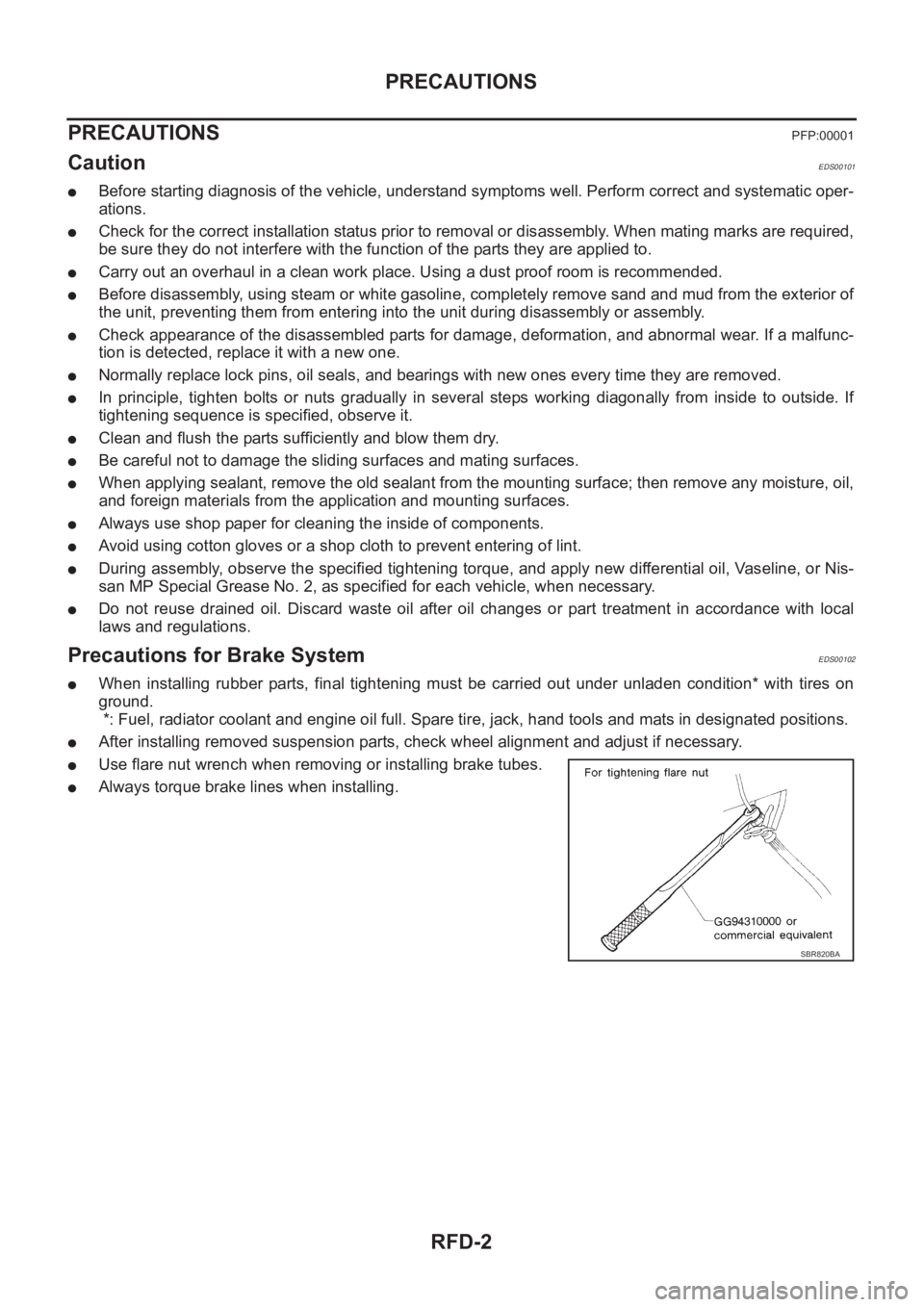
●Use flare nut wrench when removing or installing brake tubes.
●Always torque brake lines when installing.
SBR820BA
Page 2719 of 3833

SERVICE DATA AND SPECIFICATIONS (SDS)
FSU-13
C
D
F
G
H
I
J
K
L
MA
B
FSU
SERVICE DATA AND SPECIFICATIONS (SDS)PFP:00030
General SpecificationEES000J6
Wheel Alignment (Unladen)EES00079
: Fuel, radiator coolant and engine oil full. Spare tire, jack, hand tools and mats in designated positions.
Ball JointEES0007A
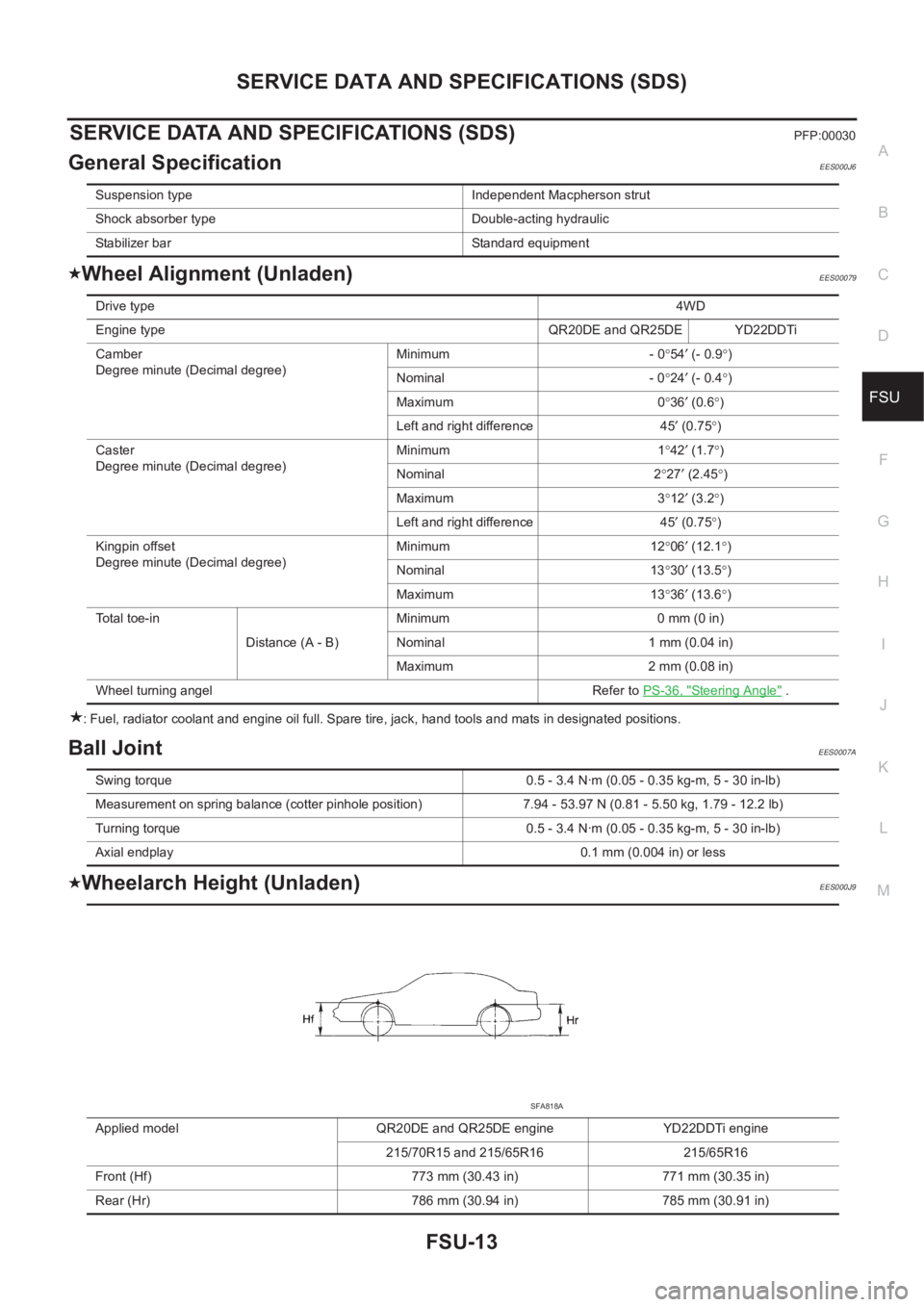
Wheelarch Height (Unladen)EES000J9
Suspension type Independent Macpherson strut
Shock absorber type Double-acting hydraulic
Stabilizer bar Standard equipment
Drive type4WD
Engine type QR20DE and QR25DE YD22DDTi
Camber
Degree minute (Decimal degree)Minimum - 0°54′ (- 0.9°)
Nominal - 0°24′ (- 0.4°)
Maximum 0°36′ (0.6°)
Left and right difference 45′ (0.75°)
Caster
Degree minute (Decimal degree)Minimum 1°42′ (1.7°)
Nominal 2°27′ (2.45°)
Maximum 3°12′ (3.2°)
Left and right difference 45′ (0.75°)
Kingpin offset
Degree minute (Decimal degree)Minimum 12°06′ (12.1°)
Nominal 13°30′ (13.5°)
Maximum 13°36′ (13.6°)
Total toe-in
Distance (A - B)Minimum 0 mm (0 in)
Nominal 1 mm (0.04 in)
Maximum 2 mm (0.08 in)
Wheel turning angel Refer to PS-36, "
Steering Angle" .
Swing torque 0.5 - 3.4 N·m (0.05 - 0.35 kg-m, 5 - 30 in-lb)
Measurement on spring balance (cotter pinhole position) 7.94 - 53.97 N (0.81 - 5.50 kg, 1.79 - 12.2 lb)
Turning torque 0.5 - 3.4 N·m (0.05 - 0.35 kg-m, 5 - 30 in-lb)
Axial endplay 0.1 mm (0.004 in) or less
Applied model QR20DE and QR25DE engine YD22DDTi engine
215/70R15 and 215/65R16 215/65R16
Front (Hf) 773 mm (30.43 in) 771 mm (30.35 in)
Rear (Hr) 786 mm (30.94 in) 785 mm (30.91 in)
SFA818A