2001 NISSAN X-TRAIL engine oil
[x] Cancel search: engine oilPage 2940 of 3833
PS-30
POWER STEERING OIL PUMP
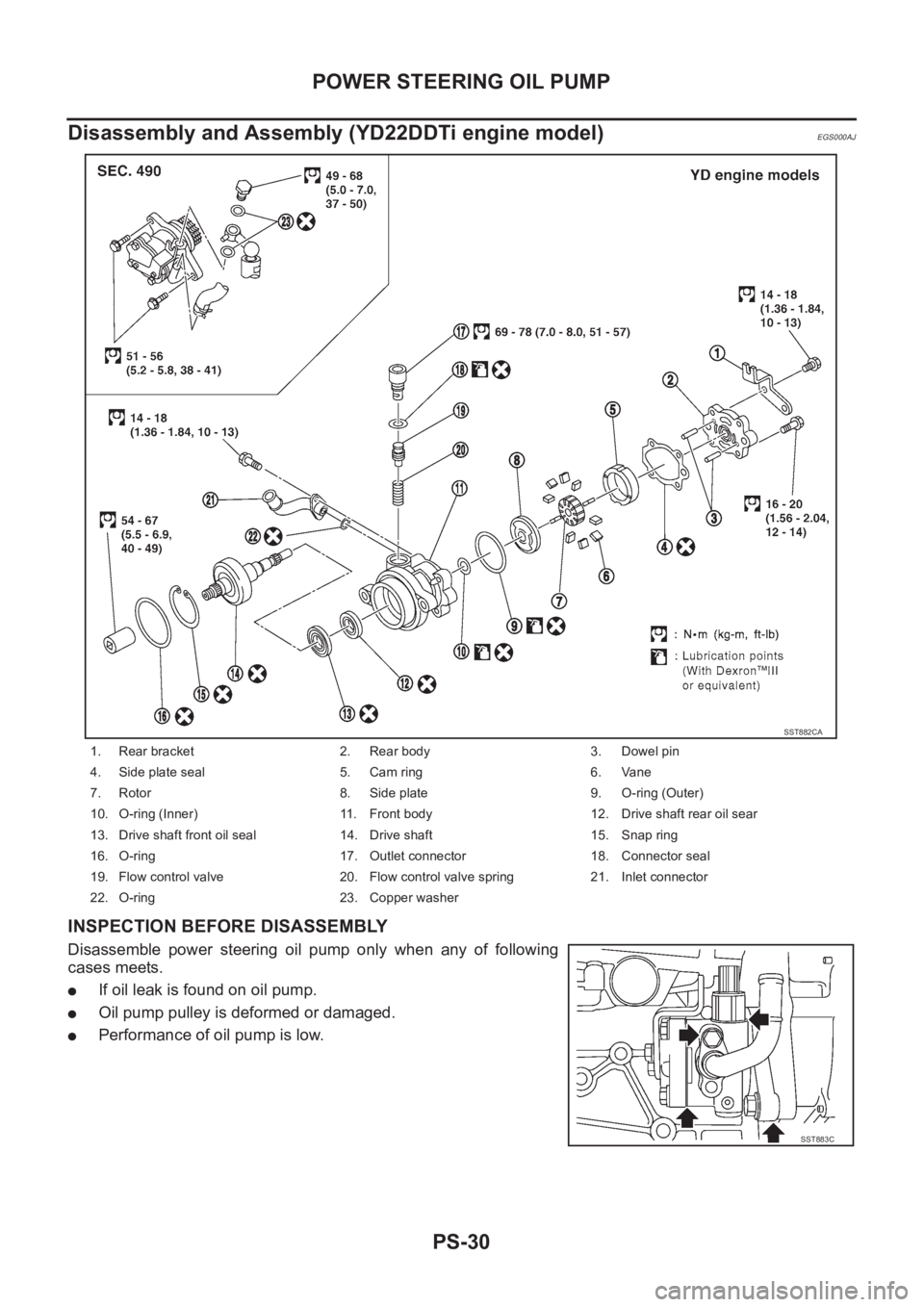
Disassembly and Assembly (YD22DDTi engine model)
EGS000AJ
INSPECTION BEFORE DISASSEMBLY
Disassemble power steering oil pump only when any of following
cases meets.
●If oil leak is found on oil pump.
●Oil pump pulley is deformed or damaged.
●Performance of oil pump is low.
1. Rear bracket 2. Rear body 3. Dowel pin
4. Side plate seal 5. Cam ring 6. Vane
7. Rotor 8. Side plate 9. O-ring (Outer)
10. O-ring (Inner) 11. Front body 12. Drive shaft rear oil sear
13. Drive shaft front oil seal 14. Drive shaft 15. Snap ring
16. O-ring 17. Outlet connector 18. Connector seal
19. Flow control valve 20. Flow control valve spring 21. Inlet connector
22. O-ring 23. Copper washer
SST882CA
SST883C
Page 2950 of 3833
FAX-2
PRECAUTIONS
PRECAUTIONS
PFP:00001
CautionEDS0005P
●When installing rubber parts, final tightening must be carried out under unladen condition* with tires on
ground.
●Oil will shorten the life of rubber bushes. Be sure to wipe off any spilled oil.
*: Fuel, radiator coolant and engine oil full. Spare tire, jack, hand tools and mats in designated positions.
●After installing removed suspension parts, check wheel alignment and adjust if necessary.
Observe the following precautions when disassembling and servicing drive shaft.
●Perform work in a location which is as dust-free and dirt-free as possible.
●Before disassembling and servicing, clean the outside of parts.
●Disassembly and service location must be taken to prevent the entry of foreign objects.
●Disassembled parts must be carefully reassembled in the correct order. If work is interrupted, a clean
cover must be placed over parts.
●Paper shop cloths must be used. Fabric shop cloths must not be used because of the danger of lint adher-
ing to parts.
●Disassembled parts (except for rubber parts) should be cleaned with kerosene which shall be removed by
blowing with air or wiping with paper shop cloths.
Page 2960 of 3833
FAX-12
FRONT DRIVE SHAFT
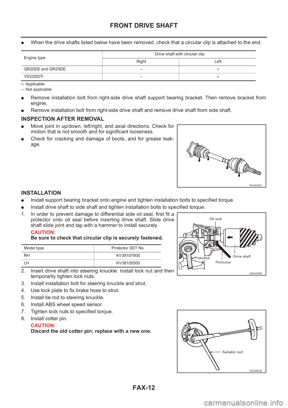
●When the drive shafts listed below have been removed, check that a circular clip is attached to the end.
×: Applicable
–: Not applicable
●Remove installation bolt from right-side drive shaft support bearing bracket. Then remove bracket from
engine.
●Remove installation bolt from right-side drive shaft and remove drive shaft from side shaft.
INSPECTION AFTER REMOVAL
●Move joint in up/down, left/right, and axial directions. Check for
motion that is not smooth and for significant looseness.
●Check for cracking and damage of boots, and for grease leak-
age.
INSTALLATION
●Install support bearing bracket onto engine and tighten installation bolts to specified torque.
●Install drive shaft to side shaft and tighten installation bolts to specified torque.
1. In order to prevent damage to differential side oil seal, first fit a
protector onto oil seal before inserting drive shaft. Slide drive
shaft slide joint and tap with a hammer to install securely.
CAUTION:
Be sure to check that circular clip is securely fastened.
2. Insert drive shaft into steering knuckle. Install lock nut and then
temporarily tighten lock nuts.
3. Install installation bolt for steering knuckle and strut.
4. Use lock plate to fix brake hose to strut.
5. Install tie rod to steering knuckle.
6. Install ABS wheel speed sensor.
7. Tighten lock nuts to specified torque.
8. Install cotter pin.
CAUTION:
Discard the old cotter pin; replace with a new one.
Engine typeDrive shaft with circular clip
Right Left
QR20DE and QR25DE –×
YD22DDTi –×
RAA0030D
Model type Protector SST No.
RH KV38107800
LH KV38105500
SDIA0593E
SDIA0603E
Page 2968 of 3833
RAX-2
PRECAUTIONS
PRECAUTIONS
PFP:00001
CautionEDS00060
●When installing rubber parts, final tightening must be carried out under unladen condition* with tires on
ground.
*: Fuel, radiator coolant and engine oil full. Spare tire, jack, hand tools and mats in designated positions.
●After installing removed suspension parts, check wheel alignment and adjust if necessary.
Observe the following precautions when disassembling and servicing drive shaft.
●Perform work in a location which is as dust-free and dirt-free as possible.
●Before disassembling and servicing, clean the outside of parts.
●The disassembly and service location must be clean. Care must be taken to prevent parts from becoming
dirty and to prevent the entry of foreign objects.
●Disassembled parts must be carefully reassembled in the correct order. If work is interrupted, a clean
cover must be placed over parts.
●Paper shop cloths must be used. Fabric shop cloths must not be used because of the danger of lint adher-
ing to parts.
●Disassembled parts (except for rubber parts) should be cleaned with kerosene which shall be removed by
blowing with air or wiping with paper shop cloths.
Page 3285 of 3833
PRECAUTIONS
ATC-9
C
D
E
F
G
H
I
K
L
MA
B
AT C
CAUTION:
When replacing or cleaning refrigerant cycle components, observe the following.
●When the compressor is removed, store it in the same position as it is when mounted on the car.
Malfunction to do so will cause lubricant to enter the low pressure chamber.
●When connecting tubes, always use a torque wrench and a back-up wrench.
●After disconnecting tubes, immediately plug all openings to prevent entry of dirt and moisture.
●When installing an air conditioner in the vehicle, connect the pipes as the final stage of the opera-
tion. Do not remove the seal caps of pipes and other components until just before required for
connection.
●Allow components stored in cool areas to warm to working area temperature before removing seal
caps. This prevents condensation from forming inside A/C components.
●Thoroughly remove moisture from the refrigeration system before charging the refrigerant.
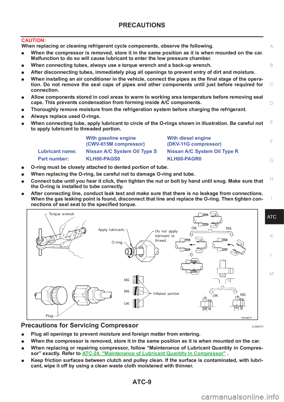
●Always replace used O-rings.
●When connecting tube, apply lubricant to circle of the O-rings shown in illustration. Be careful not
to apply lubricant to threaded portion.
●O-ring must be closely attached to dented portion of tube.
●When replacing the O-ring, be careful not to damage O-ring and tube.
●Connect tube until you hear it click, then tighten the nut or bolt by hand until snug. Make sure that
the O-ring is installed to tube correctly.
●After connecting line, conduct leak test and make sure that there is no leakage from connections.
When the gas leaking point is found, disconnect that line and replace the O-ring. Then tighten con-
nections of seal seat to the specified torque.
Precautions for Servicing CompressorEJS000T5
●Plug all openings to prevent moisture and foreign matter from entering.
●When the compressor is removed, store it in the same position as it is when mounted on the car.
●When replacing or repairing compressor, follow “Maintenance of Lubricant Quantity in Compres-
sor” exactly. Refer to ATC-24, "
Maintenance of Lubricant Quantity in Compressor" .
●Keep friction surfaces between clutch and pulley clean. If the surface is contaminated, with lubri-
cant, wipe it off by using a clean waste cloth moistened with thinner. With gasoline engine
(CWV-615M compressor)With diesel engine
(DKV-11G compressor)
Lubricant name: Nissan A/C System Oil Type S Nissan A/C System Oil Type R
Part number: KLH00-PAGS0 KLH00-PAGR0
RHA861F
Page 3286 of 3833
ATC-10
PRECAUTIONS
●After compressor service operation, turn the compressor shaft by hand more than five turns in
both directions. This will equally distribute lubricant inside the compressor. After the compressor
is installed, let the engine idle and operate the compressor for one hour.
●After replacing the compressor magnet clutch, apply voltage to the new one and check for normal
operation.
Precautions for Service EquipmentEJS000T6
RECOVERY/RECYCLING EQUIPMENT
Be certain to follow the manufacturers instructions for machine operation and machine maintenance. Never
introduce any refrigerant other than that specified into the machine.
ELECTRONIC LEAK DETECTOR
Be certain to follow the manufacturer's instructions for tester operation and tester maintenance.
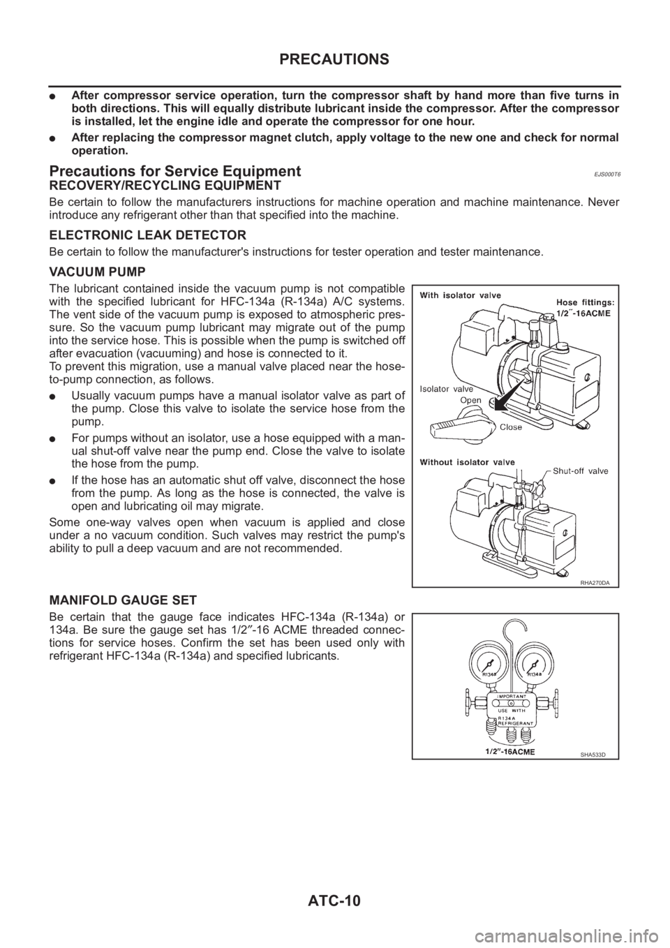
VACUUM PUMP
The lubricant contained inside the vacuum pump is not compatible
with the specified lubricant for HFC-134a (R-134a) A/C systems.
The vent side of the vacuum pump is exposed to atmospheric pres-
sure. So the vacuum pump lubricant may migrate out of the pump
into the service hose. This is possible when the pump is switched off
after evacuation (vacuuming) and hose is connected to it.
To prevent this migration, use a manual valve placed near the hose-
to-pump connection, as follows.
●Usually vacuum pumps have a manual isolator valve as part of
the pump. Close this valve to isolate the service hose from the
pump.
●For pumps without an isolator, use a hose equipped with a man-
ual shut-off valve near the pump end. Close the valve to isolate
the hose from the pump.
●If the hose has an automatic shut off valve, disconnect the hose
from the pump. As long as the hose is connected, the valve is
open and lubricating oil may migrate.
Some one-way valves open when vacuum is applied and close
under a no vacuum condition. Such valves may restrict the pump's
ability to pull a deep vacuum and are not recommended.
MANIFOLD GAUGE SET
Be certain that the gauge face indicates HFC-134a (R-134a) or
134a. Be sure the gauge set has 1/2″-16 ACME threaded connec-
tions for service hoses. Confirm the set has been used only with
refrigerant HFC-134a (R-134a) and specified lubricants.
RHA270DA
SHA533D
Page 3291 of 3833
PREPARATION
ATC-15
C
D
E
F
G
H
I
K
L
MA
B
AT C
HFC-134a (R-134a) Service Tools and EquipmentEJS00286
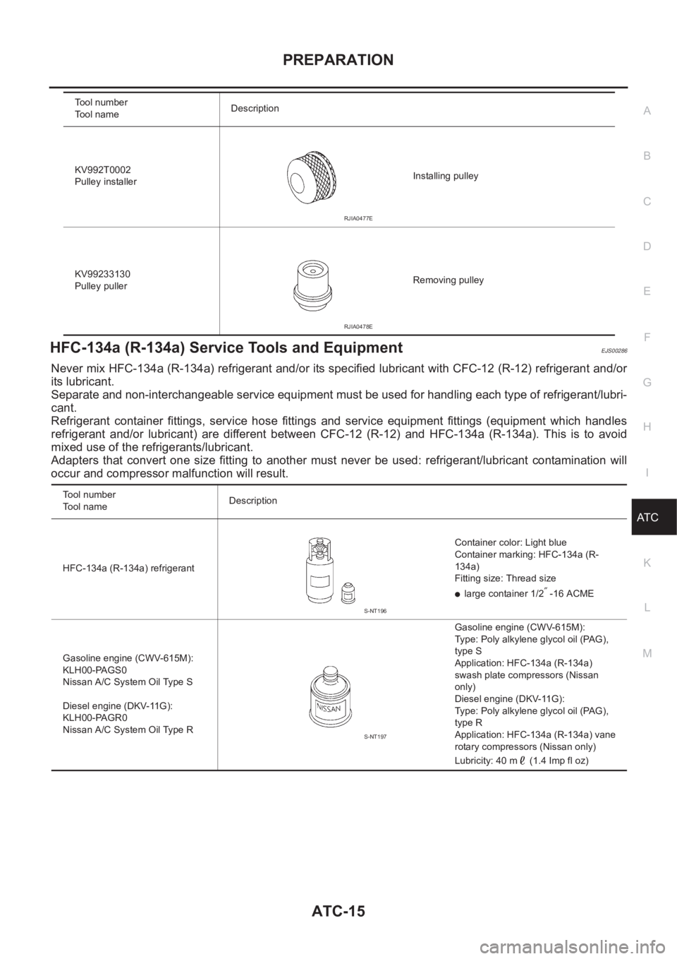
Never mix HFC-134a (R-134a) refrigerant and/or its specified lubricant with CFC-12 (R-12) refrigerant and/or
its lubricant.
Separate and non-interchangeable service equipment must be used for handling each type of refrigerant/lubri-
cant.
Refrigerant container fittings, service hose fittings and service equipment fittings (equipment which handles
refrigerant and/or lubricant) are different between CFC-12 (R-12) and HFC-134a (R-134a). This is to avoid
mixed use of the refrigerants/lubricant.
Adapters that convert one size fitting to another must never be used: refrigerant/lubricant contamination will
occur and compressor malfunction will result.
KV992T0002
Pulley installerInstalling pulley
KV99233130
Pulley pullerRemoving pulley Tool number
Tool nameDescription
RJIA0477E
RJIA0478E
Tool number
To o l n a m eDescription
HFC-134a (R-134a) refrigerantContainer color: Light blue
Container marking: HFC-134a (R-
134a)
Fitting size: Thread size
●large container 1/2″ -16 ACME
Gasoline engine (CWV-615M):
KLH00-PAGS0
Nissan A/C System Oil Type S
Diesel engine (DKV-11G):
KLH00-PAGR0
Nissan A/C System Oil Type RGasoline engine (CWV-615M):
Type: Poly alkylene glycol oil (PAG),
type S
Application: HFC-134a (R-134a)
swash plate compressors (Nissan
only)
Diesel engine (DKV-11G):
Type: Poly alkylene glycol oil (PAG),
type R
Application: HFC-134a (R-134a) vane
rotary compressors (Nissan only)
Lubricity: 40 m (1.4 Imp fl oz)
S-NT196
S-NT197
Page 3294 of 3833
ATC-18
REFRIGERATION SYSTEM
REFRIGERATION SYSTEM
PFP:KA990
Refrigerant CycleEJS000TD
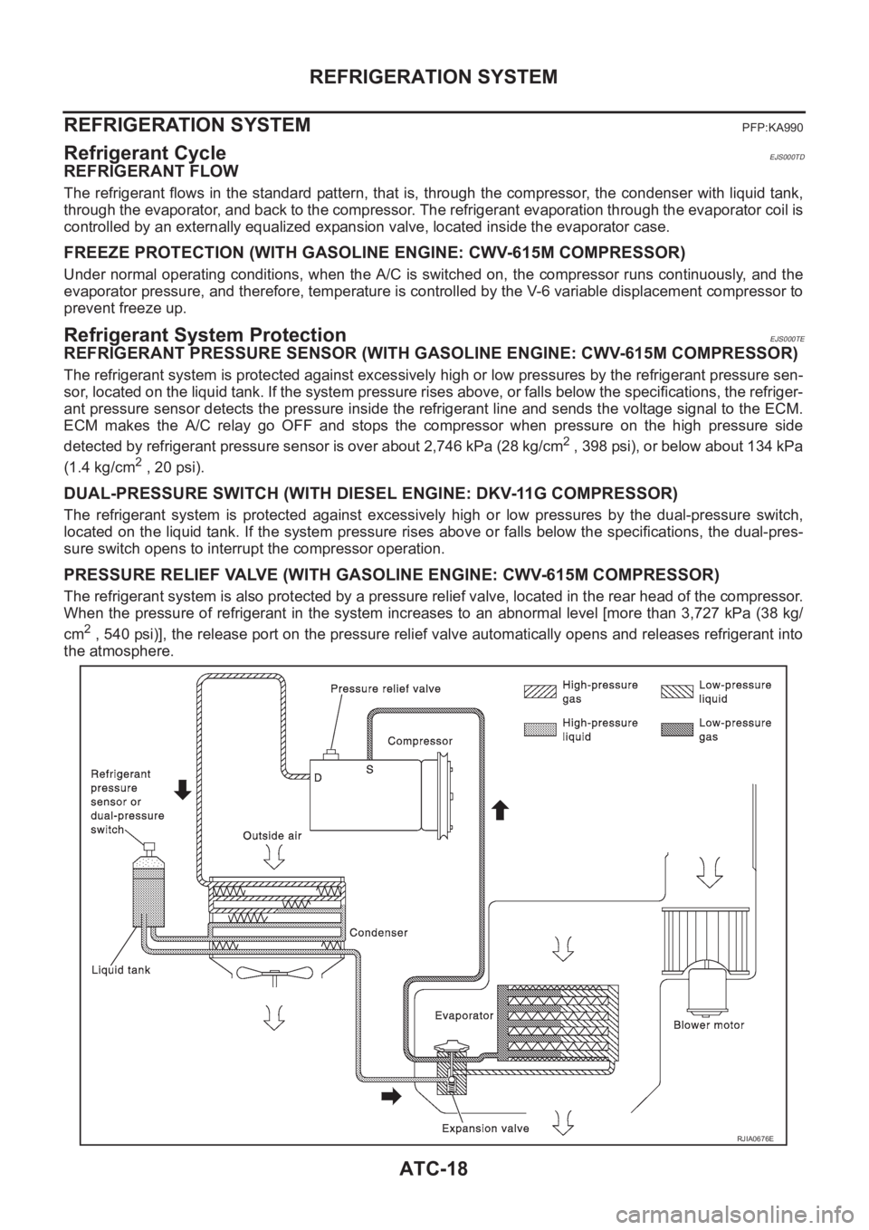
REFRIGERANT FLOW
The refrigerant flows in the standard pattern, that is, through the compressor, the condenser with liquid tank,
through the evaporator, and back to the compressor. The refrigerant evaporation through the evaporator coil is
controlled by an externally equalized expansion valve, located inside the evaporator case.
FREEZE PROTECTION (WITH GASOLINE ENGINE: CWV-615M COMPRESSOR)
Under normal operating conditions, when the A/C is switched on, the compressor runs continuously, and the
evaporator pressure, and therefore, temperature is controlled by the V-6 variable displacement compressor to
prevent freeze up.
Refrigerant System ProtectionEJS000TE
REFRIGERANT PRESSURE SENSOR (WITH GASOLINE ENGINE: CWV-615M COMPRESSOR)
The refrigerant system is protected against excessively high or low pressures by the refrigerant pressure sen-
sor, located on the liquid tank. If the system pressure rises above, or falls below the specifications, the refriger-
ant pressure sensor detects the pressure inside the refrigerant line and sends the voltage signal to the ECM.
ECM makes the A/C relay go OFF and stops the compressor when pressure on the high pressure side
detected by refrigerant pressure sensor is over about 2,746 kPa (28 kg/cm
2 , 398 psi), or below about 134 kPa
(1.4 kg/cm
2 , 20 psi).
DUAL-PRESSURE SWITCH (WITH DIESEL ENGINE: DKV-11G COMPRESSOR)
The refrigerant system is protected against excessively high or low pressures by the dual-pressure switch,
located on the liquid tank. If the system pressure rises above or falls below the specifications, the dual-pres-
sure switch opens to interrupt the compressor operation.
PRESSURE RELIEF VALVE (WITH GASOLINE ENGINE: CWV-615M COMPRESSOR)
The refrigerant system is also protected by a pressure relief valve, located in the rear head of the compressor.
When the pressure of refrigerant in the system increases to an abnormal level [more than 3,727 kPa (38 kg/
cm
2 , 540 psi)], the release port on the pressure relief valve automatically opens and releases refrigerant into
the atmosphere.
RJIA0676E