2001 NISSAN X-TRAIL engine oil
[x] Cancel search: engine oilPage 2749 of 3833
BRAKE FLUID
BR-9
C
D
E
G
H
I
J
K
L
MA
B
BR
BRAKE FLUIDPFP:KN100
Checking Brake Fluid Level EFS000C5
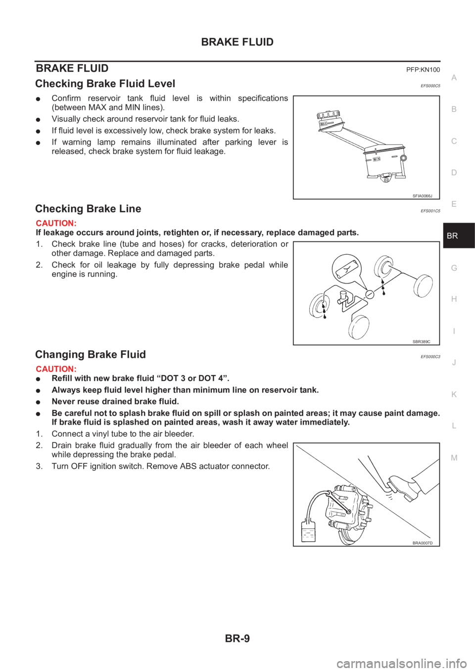
●Confirm reservoir tank fluid level is within specifications
(between MAX and MIN lines).
●Visually check around reservoir tank for fluid leaks.
●If fluid level is excessively low, check brake system for leaks.
●If warning lamp remains illuminated after parking lever is
released, check brake system for fluid leakage.
Checking Brake LineEFS001C5
CAUTION:
If leakage occurs around joints, retighten or, if necessary, replace damaged parts.
1. Check brake line (tube and hoses) for cracks, deterioration or
other damage. Replace and damaged parts.
2. Check for oil leakage by fully depressing brake pedal while
engine is running.
Changing Brake FluidEFS000C3
CAUTION:
●Refill with new brake fluid “DOT 3 or DOT 4”.
●Always keep fluid level higher than minimum line on reservoir tank.
●Never reuse drained brake fluid.
●Be careful not to splash brake fluid on spill or splash on painted areas; it may cause paint damage.
If brake fluid is splashed on painted areas, wash it away water immediately.
1. Connect a vinyl tube to the air bleeder.
2. Drain brake fluid gradually from the air bleeder of each wheel
while depressing the brake pedal.
3. Turn OFF ignition switch. Remove ABS actuator connector.
SFIA0066J
SBR389C
BRA0007D
Page 2838 of 3833
![NISSAN X-TRAIL 2001 Service Repair Manual BRC-54
[ESP/TCS/ABS]
PRECAUTIONS
[ESP/TCS/ABS]PRECAUTIONSPFP:00001
Precautions for Brake SystemEFS0019O
●Recommended fluid is brake fluid “DOT 3” or “DOT 4”.
●Never reuse drained brake flu NISSAN X-TRAIL 2001 Service Repair Manual BRC-54
[ESP/TCS/ABS]
PRECAUTIONS
[ESP/TCS/ABS]PRECAUTIONSPFP:00001
Precautions for Brake SystemEFS0019O
●Recommended fluid is brake fluid “DOT 3” or “DOT 4”.
●Never reuse drained brake flu](/manual-img/5/57405/w960_57405-2837.png)
BRC-54
[ESP/TCS/ABS]
PRECAUTIONS
[ESP/TCS/ABS]PRECAUTIONSPFP:00001
Precautions for Brake SystemEFS0019O
●Recommended fluid is brake fluid “DOT 3” or “DOT 4”.
●Never reuse drained brake fluid.
●Be careful not to splash brake fluid on painted areas; it may cause paint damage. If brake fluid is splashed
on painted areas, wash it away with water immediately.
●Never use mineral oils such as gasoline or kerosene. They will ruin rubber parts of hydraulic system.
●Use flare nut wrench when removing and installing brake tubes.
●Always torque brake lines when installing.
●Before working, turn the ignition switch OFF and disconnect the
connectors for the ESP/TCS/ABS actuator and control unit or
the battery terminals.
●Burnish the brake contact surfaces after refinishing or replacing
drums or rotors, after replacing pads or linings, or if a soft pedal
occurs at very low mileage. Refer to BR-10, "
Brake Burnishing
Procedure" .
WARNING:
Clean brakes with a vacuum dust collector to minimize risk
of health hazard from powder caused by friction.
Precautions for Brake ControlEFS0019P
●During the ESP/TCS/ABS operation, the brake pedal vibrates lightly and its mechanical noise may be
heard. This is a normal condition.
●Just after starting the vehicle after ignition switch ON, the brake pedal may vibrate or the motor operating
noise may be heard from the engine compartment. This is a normal status of the operation check.
●The stopping distance may be longer than that of vehicles without ABS when the vehicle drives on rough,
gravel, or snowy (fresh deep snow) road.
●If a malfunction is indicated by the ABS warning lamp, or other warning lamps, collect the necessary infor-
mation from the customer (what symptoms are present under what conditions) and find out the possible
causes before starting the service. Besides the electrical system inspection, check the booster operation,
brake fluid level, and oil leaks.
●If the tire size and type are used in a improper combination, or the brake pads are not NISSAN genuine
parts, the stopping distance or steering stability may deteriorate.
●If there is a radio, antenna, or antenna lead-in wire (including wiring) near the control unit, the ESP/TCS/
ABS function may have a malfunction or error.
●If aftermarket parts (e.g. Car stereo equipment, CD player) have been installed, check the electrical har-
nesses for pinches, open, and improper wiring.
Precautions for CAN SystemEFS001CP
FOR INSPECTION
●Do not apply voltage of 7.0V or higher to the measurement terminals.
●Use the tester with its open terminal voltage being 7.0V or less.
●Before harness inspection, turn the ignition switch off, disconnect the negative battery terminal.
SBR820BA
Page 2911 of 3833
PS-1
POWER STEERING SYSTEM
G STEERING
CONTENTS
C
D
E
F
H
I
J
K
L
M
SECTION
A
B
PS
POWER STEERING SYSTEM
PRECAUTIONS .......................................................... 2
Precautions for Supplemental Restraint System
(SRS) “AIR BAG” and “SEAT BELT PRE-TEN-
SIONER” .................................................................. 2
Caution ..................................................................... 2
PREPARATION ........................................................... 3
Special Service Tools ............................................... 3
NOISE, VIBRATION, AND HARSHNESS (NVH)
TROUBLESHOOTING ................................................ 4
NVH Trouble shooting Chart .................................... 4
POWER STEERING FLUID ........................................ 5
Checking Fluid Level ........................................... ..... 5
Checking Fluid Leak ............................................ ..... 5
Bleeding Hydraulic System ...................................... 5
STEERING WHEEL .................................................... 6
On-Vehicle Inspection and Service .......................... 6
PLAY INSPECTION .............................................. 6
NEUTRAL POSITION INSPECTION .................... 6
STEERING TORQUE CHECK .............................. 6
STEERING ANGLE INSPECTION ........................ 6
Removal and Installation .......................................... 7
REMOVAL ............................................................. 7
INSTALLATION ..................................................... 7
STEERING COLUMN ................................................. 9
Removal and Installation .......................................... 9
REMOVAL OF LOWER JOINT AND HOLE
COVER ................................................................. 9
INSTALLATION OF LOWER JOINT AND HOLE
COVER ................................................................. 9
REMOVAL OF STEERING COLUMN ASSEM-
BLY ...................................................................... 10
INSTALLING STEERING COLUMN ASSEMBLY ... 10
Disassembly and Assembly .................................... 11
DISASSEMBLY .................................................... 11
INSPECTION AFTER DISASSEMBLY. ............... 11
ASSEMBLY .......................................................... 11
POWER STEERING GEAR AND LINKAGE ............ 12
Removal and Installation ........................................ 12
REMOVAL ........................................................... 12INSTALLATION ................................................... 12
Components ........................................................... 14
MODEL PR24AD ................................................. 14
Disassembly and Assembly .................................... 15
DISASSEMBLY ................................................... 15
INSPECTION AFTER DISASSEMBLY ................ 16
ASSEMBLY ......................................................... 17
POWER STEERING OIL PUMP ............................... 24
On-Vehicle Inspection and Service ......................... 24
OIL PUMP PULLEY HYDRAULIC PRESSURE
INSPECTION ...................................................... 24
Removal and Installation (QR20DE and QR25DE
engine models) ....................................................... 24
REMOVAL ........................................................... 24
INSTALLATION ................................................... 24
Disassembly and Assembly(QR20DE and
QR25DE engine models) ........................................ 25
INSPECTION BEFORE DISASSEMBLY ............. 25
DISASSEMBLY ................................................... 25
INSPECTION AFTER DISASSEMBLY ................ 26
ASSEMBLY ......................................................... 26
Removal and Installation (YD22DDTi engine
model) ..................................................................... 29
Disassembly and Assembly (YD22DDTi engine
model) ..................................................................... 30
INSPECTION BEFORE DISASSEMBLY ............. 30
DISASSEMBLY ................................................... 31
INSPECTION AFTER DISASSEMBLY ................ 32
ASSEMBLY ......................................................... 32
HYDRAULIC LINE .................................................
... 34
Removal and Installation ........................................ 34
SERVICE DATA AND SPECIFICATIONS (SDS) ...... 36
Wheel ..................................................................... 36
Steering Angle ........................................................ 36
Steering Column ..................................................... 36
Steering Linkage ..................................................... 36
Steering Gear ......................................................... 37
Oil Pump ................................................................. 37
Steering Fluid .......................................................... 37
Page 2915 of 3833
POWER STEERING FLUID
PS-5
C
D
E
F
H
I
J
K
L
MA
B
PS
POWER STEERING FLUIDPFP:KLF20
Checking Fluid LevelEGS0004B
●Check the fluid level with the engine OFF.
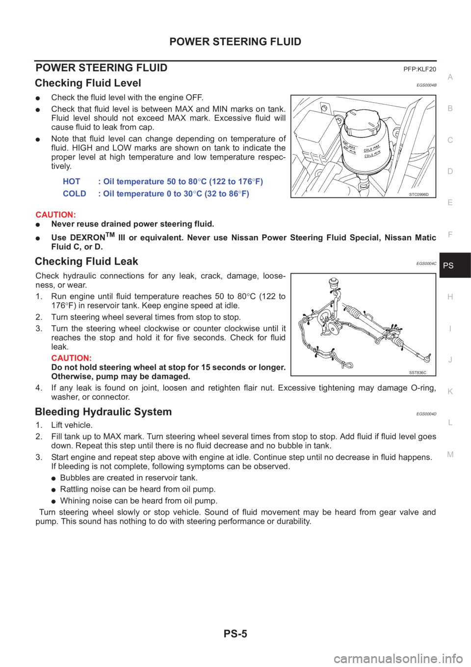
●Check that fluid level is between MAX and MIN marks on tank.
Fluid level should not exceed MAX mark. Excessive fluid will
cause fluid to leak from cap.
●Note that fluid level can change depending on temperature of
fluid. HIGH and LOW marks are shown on tank to indicate the
proper level at high temperature and low temperature respec-
tively.
CAUTION:
●Never reuse drained power steering fluid.
●Use DEXRONTM III or equivalent. Never use Nissan Power Steering Fluid Special, Nissan Matic
Fluid C, or D.
Checking Fluid LeakEGS0004C
Check hydraulic connections for any leak, crack, damage, loose-
ness, or wear.
1. Run engine until fluid temperature reaches 50 to 80°C (122 to
176°F) in reservoir tank. Keep engine speed at idle.
2. Turn steering wheel several times from stop to stop.
3. Turn the steering wheel clockwise or counter clockwise until it
reaches the stop and hold it for five seconds. Check for fluid
leak.
CAUTION:
Do not hold steering wheel at stop for 15 seconds or longer.
Otherwise, pump may be damaged.
4. If any leak is found on joint, loosen and retighten flair nut. Excessive tightening may damage O-ring,
washer, or connector.
Bleeding Hydraulic SystemEGS0004D
1. Lift vehicle.
2. Fill tank up to MAX mark. Turn steering wheel several times from stop to stop. Add fluid if fluid level goes
down. Repeat this step until there is no fluid decrease and no bubble in tank.
3. Start engine and repeat step above with engine at idle. Continue step until no decrease in fluid happens.
If bleeding is not complete, following symptoms can be observed.
●Bubbles are created in reservoir tank.
●Rattling noise can be heard from oil pump.
●Whining noise can be heard from oil pump.
Turn steering wheel slowly or stop vehicle. Sound of fluid movement may be heard from gear valve and
pump. This sound has nothing to do with steering performance or durability. HOT : Oil temperature 50 to 80°C (122 to 176°F)
COLD : Oil temperature 0 to 30°C (32 to 86°F)
STC0996D
SST836C
Page 2916 of 3833
PS-6
STEERING WHEEL
STEERING WHEEL
PFP:48430
On-Vehicle Inspection and ServiceEGS0004E
PLAY INSPECTION
1. Turn steering wheel to straight-ahead position. Start engine and lightly turn steering wheel clockwise and
counter clockwise until front wheels start moving. Measure travel to starting point on circumference of
steering wheel.
2. If play is outside specifications, check following parts for proper installation: steering gear assembly, front
suspension, axles, and steering column
●Check steering wheel for vertical, horizontal, or axial play.
●Lift vehicle and check steering gear mounting bolts and nuts for looseness.
NEUTRAL POSITION INSPECTION
●After the wheel alignment inspection, carry out the neutral position inspection. Refer to FSU-6, "Wheel
Alignment" .
●Before removing steering wheel, check steering gear neutral position.
1. Set vehicle to straight-ahead position, and check that steering wheel is in neutral position.
2. If it is not in neutral position, remove steering wheel, and install again in properly.
3. If it is not adjusted within two teeth from center of gear, loosen tie rod lock nut. Then turn it to opposite
direction to adjust until amount of left and right becomes equal.
STEERING TORQUE CHECK
1. Stop vehicle on a dry flat paved road and apply parking brake.
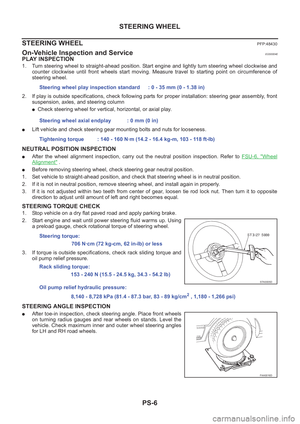
2. Start engine and wait until power steering fluid warms up. Using
a preload gauge, check rotational torque of steering wheel.
3. If torque is outside specifications, check rack sliding torque and
oil pump relief pressure.
STEERING ANGLE INSPECTION
●After toe-in inspection, check steering angle. Place front wheels
on turning radius gauges and rear wheels on stands. Level the
vehicle. Check maximum inner and outer wheel steering angles
for LH and RH road wheels.Steering wheel play inspection standard : 0 - 35 mm (0 - 1.38 in)
Steering wheel axial endplay : 0 mm (0 in)
Tightening torque : 140 - 160 N·m (14.2 - 16.4 kg-m, 103 - 118 ft-lb)
Steering torque:
706 N·cm (72 kg-cm, 62 in-lb) or less
Rack sliding torque:
153 - 240 N (15.5 - 24.5 kg, 34.3 - 54.2 lb)
Oil pump relief hydraulic pressure:
8,140 - 8,728 kPa (81.4 - 87.3 bar, 83 - 89 kg/cm
2 , 1,180 - 1,266 psi)
STA0005D
FAA0016D
Page 2934 of 3833
PS-24
POWER STEERING OIL PUMP
POWER STEERING OIL PUMP
PFP:49110
On-Vehicle Inspection and ServiceEGS000AF
OIL PUMP PULLEY HYDRAULIC PRESSURE INSPECTION
Before starting following procedure, check tension of belt.
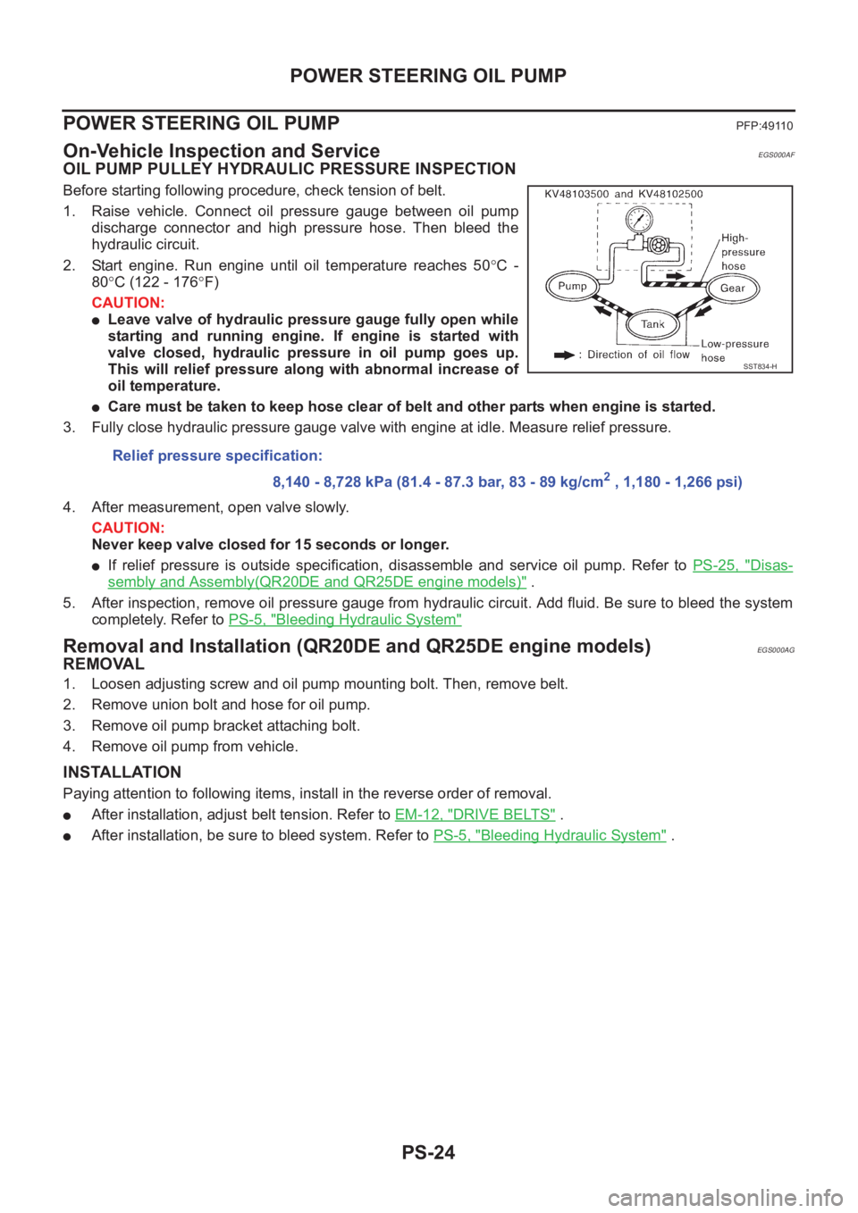
1. Raise vehicle. Connect oil pressure gauge between oil pump
discharge connector and high pressure hose. Then bleed the
hydraulic circuit.
2. Start engine. Run engine until oil temperature reaches 50°C -
80°C (122 - 176°F)
CAUTION:
●Leave valve of hydraulic pressure gauge fully open while
starting and running engine. If engine is started with
valve closed, hydraulic pressure in oil pump goes up.
This will relief pressure along with abnormal increase of
oil temperature.
●Care must be taken to keep hose clear of belt and other parts when engine is started.
3. Fully close hydraulic pressure gauge valve with engine at idle. Measure relief pressure.
4. After measurement, open valve slowly.
CAUTION:
Never keep valve closed for 15 seconds or longer.
●If relief pressure is outside specification, disassemble and service oil pump. Refer to PS-25, "Disas-
sembly and Assembly(QR20DE and QR25DE engine models)" .
5. After inspection, remove oil pressure gauge from hydraulic circuit. Add fluid. Be sure to bleed the system
completely. Refer to PS-5, "
Bleeding Hydraulic System"
Removal and Installation (QR20DE and QR25DE engine models)EGS000AG
REMOVAL
1. Loosen adjusting screw and oil pump mounting bolt. Then, remove belt.
2. Remove union bolt and hose for oil pump.
3. Remove oil pump bracket attaching bolt.
4. Remove oil pump from vehicle.
INSTALLATION
Paying attention to following items, install in the reverse order of removal.
●After installation, adjust belt tension. Refer to EM-12, "DRIVE BELTS" .
●After installation, be sure to bleed system. Refer to PS-5, "Bleeding Hydraulic System" . Relief pressure specification:
8,140 - 8,728 kPa (81.4 - 87.3 bar, 83 - 89 kg/cm
2 , 1,180 - 1,266 psi)
SST834-H
Page 2935 of 3833
POWER STEERING OIL PUMP
PS-25
C
D
E
F
H
I
J
K
L
MA
B
PS
Disassembly and Assembly(QR20DE and QR25DE engine models)EGS000AH
INSPECTION BEFORE DISASSEMBLY
Disassemble the power steering oil pump only if the following items
are found.
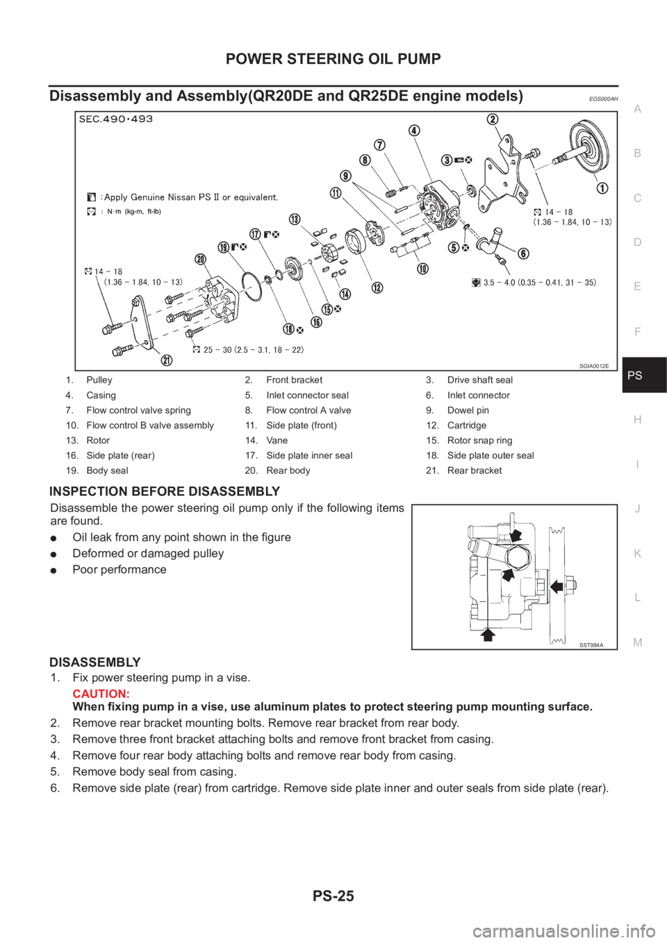
●Oil leak from any point shown in the figure
●Deformed or damaged pulley
●Poor performance
DISASSEMBLY
1. Fix power steering pump in a vise.
CAUTION:
When fixing pump in a vise, use aluminum plates to protect steering pump mounting surface.
2. Remove rear bracket mounting bolts. Remove rear bracket from rear body.
3. Remove three front bracket attaching bolts and remove front bracket from casing.
4. Remove four rear body attaching bolts and remove rear body from casing.
5. Remove body seal from casing.
6. Remove side plate (rear) from cartridge. Remove side plate inner and outer seals from side plate (rear).
1. Pulley 2. Front bracket 3. Drive shaft seal
4. Casing 5. Inlet connector seal 6. Inlet connector
7. Flow control valve spring 8. Flow control A valve 9. Dowel pin
10. Flow control B valve assembly 11. Side plate (front) 12. Cartridge
13. Rotor 14. Vane 15. Rotor snap ring
16. Side plate (rear) 17. Side plate inner seal 18. Side plate outer seal
19. Body seal 20. Rear body 21. Rear bracket
SGIA0012E
SST984A
Page 2939 of 3833
POWER STEERING OIL PUMP
PS-29
C
D
E
F
H
I
J
K
L
MA
B
PS
Removal and Installation (YD22DDTi engine model)EGS000AI
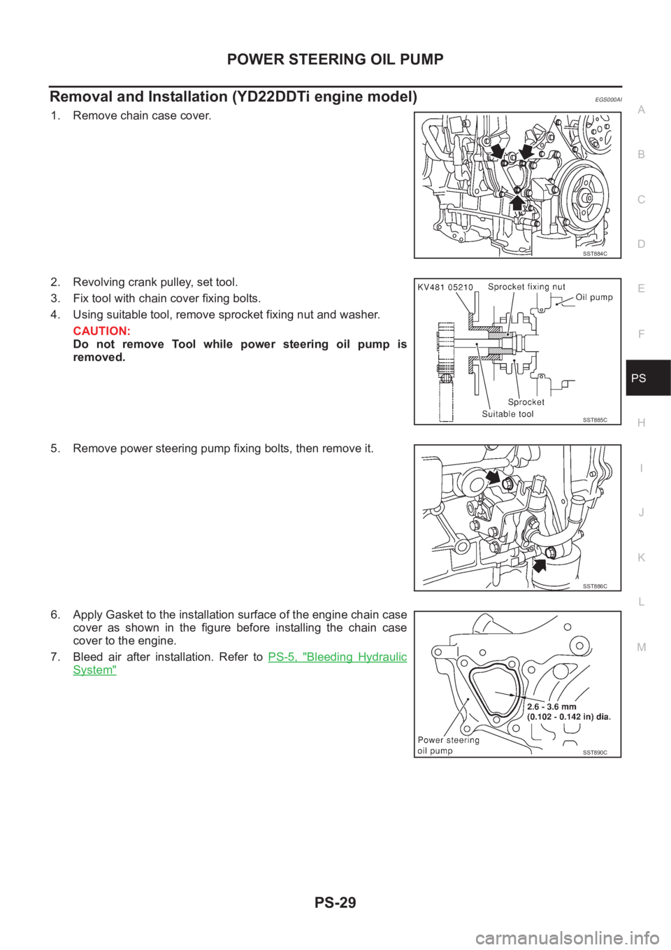
1. Remove chain case cover.
2. Revolving crank pulley, set tool.
3. Fix tool with chain cover fixing bolts.
4. Using suitable tool, remove sprocket fixing nut and washer.
CAUTION:
Do not remove Tool while power steering oil pump is
removed.
5. Remove power steering pump fixing bolts, then remove it.
6. Apply Gasket to the installation surface of the engine chain case
cover as shown in the figure before installing the chain case
cover to the engine.
7. Bleed air after installation. Refer to PS-5, "
Bleeding Hydraulic
System"
SST884C
SST885C
SST886C
SST890C