2001 NISSAN X-TRAIL engine oil
[x] Cancel search: engine oilPage 2600 of 3833
![NISSAN X-TRAIL 2001 Service Repair Manual AT-522
[ALL]
SERVICE DATA AND SPECIFICATIONS (SDS)
Stall Revolution
ECS004MK
Line PressureECS004ML
Control ValvesECS004MM
CONTROL VALVE AND PLUG RETURN SPRINGS
For 85X23 model
Unit: mm (in)
*: Always NISSAN X-TRAIL 2001 Service Repair Manual AT-522
[ALL]
SERVICE DATA AND SPECIFICATIONS (SDS)
Stall Revolution
ECS004MK
Line PressureECS004ML
Control ValvesECS004MM
CONTROL VALVE AND PLUG RETURN SPRINGS
For 85X23 model
Unit: mm (in)
*: Always](/manual-img/5/57405/w960_57405-2599.png)
AT-522
[ALL]
SERVICE DATA AND SPECIFICATIONS (SDS)
Stall Revolution
ECS004MK
Line PressureECS004ML
Control ValvesECS004MM
CONTROL VALVE AND PLUG RETURN SPRINGS
For 85X23 model
Unit: mm (in)
*: Always check with the Parts Department for the latest parts information. EngineStall revolutio n
rpm
QR20DE 2,450 - 2,950
QR25DE 2,300 - 2,750
Engine speed
rpmLine pressure kPa (kg/cm2 , psi)
D, 2 and 1 positions R position
Idle 500 (5.1, 73) 778 (7.9, 113)
Stall 1,233 (12.6, 179) 1,918 (19.6, 278)
PartsItem
Part No.* Free length Outer diameter
Upper body23 Pilot valve spring 31742-3AX03 38.98 (1.535) 8.9 (0.350)
7 1-2 accumulator valve spring 31742-3AX00 20.5 (0.807) 6.95 (0.274)
28 1-2 accumulator piston spring 31742-85X02 55.60 (2.189) 19.6 (0.772)
33 1st reducing valve spring 31742-80X05 27.0 (1.063) 7.0 (0.276)
35 3-2 timing valve spring 31736-01X00 23.0 (0.906) 6.65 (0.262)
18 Overrun clutch reducing valve spring 31742-80X15 37.5 (1.476) 6.9 (0.272)
16 Torque converter relief valve spring 31742-80X07 31.0 (1.220) 9.0 (0.354)
11 Torque converter clutch control valve 31742-85X00 56.98 (2.243)6.5 (0.256)
3 Cooler check valve spring 31742-85X01 29.4 (1.157) 6.0 (0.236)
Lower body15 Pressure regulator valve spring 31742-80X13 45.0 (1.772) 15.0 (0.591)
20 Overrun clutch control valve spring 31762-80X00 21.7 (0.854) 7.0 (0.276)
24 Accumulator control valve spring 31742-80X02 22.0 (0.866) 6.5 (0.256)
29 Shift valve A spring 31762-80X00 21.7 (0.854) 7.0 (0.276)
32 Shuttle valve spring 31762-41X04 51.0 (2.008) 5.65 (0.222)
12 Shift valve B spring 31762-80X00 21.7 (0.854) 7.0 (0.276)
7
Pressure modifier valve spring31742-41X15 30.5 (1.201) 9.8 (0.386)
3 31742-80X16 32.0 (1.260) 6.9 (0.272)
— Oil cooler relief valve spring 31872-31X00 17.02 (0.670) 8.0 (0.315)
Page 2618 of 3833
TF-8
TRANSFER FLUID
TRANSFER FLUID
PFP:KLD30
ReplacementEDS0004Q
DRAINING
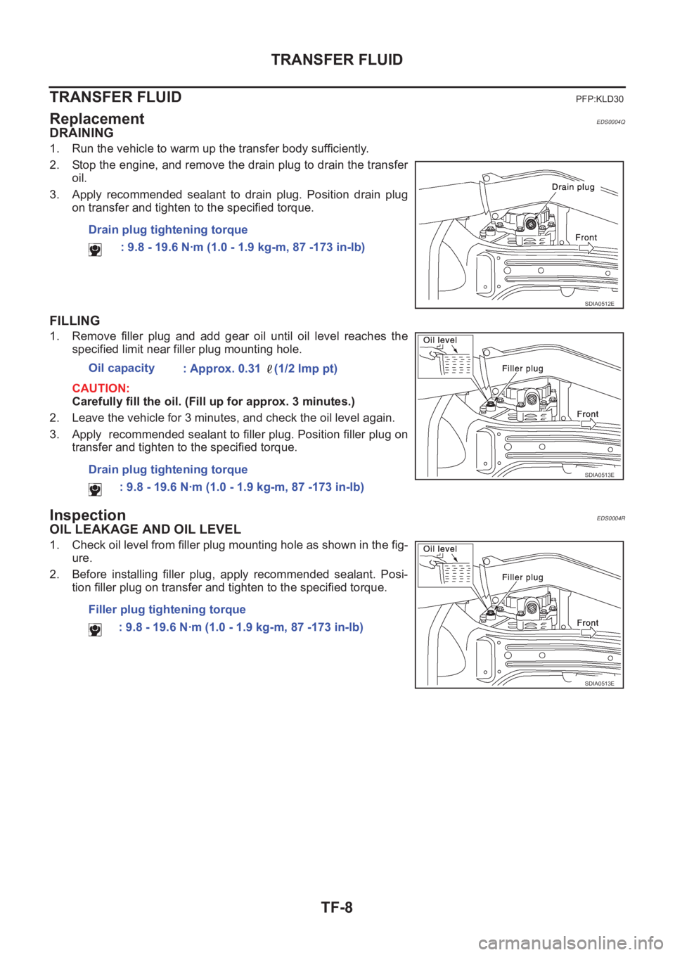
1. Run the vehicle to warm up the transfer body sufficiently.
2. Stop the engine, and remove the drain plug to drain the transfer
oil.
3. Apply recommended sealant to drain plug. Position drain plug
on transfer and tighten to the specified torque.
FILLING
1. Remove filler plug and add gear oil until oil level reaches the
specified limit near filler plug mounting hole.
CAUTION:
Carefully fill the oil. (Fill up for approx. 3 minutes.)
2. Leave the vehicle for 3 minutes, and check the oil level again.
3. Apply recommended sealant to filler plug. Position filler plug on
transfer and tighten to the specified torque.
InspectionEDS0004R
OIL LEAKAGE AND OIL LEVEL
1. Check oil level from filler plug mounting hole as shown in the fig-
ure.
2. Before installing filler plug, apply recommended sealant. Posi-
tion filler plug on transfer and tighten to the specified torque. Drain plug tightening torque
: 9.8 - 19.6 N·m (1.0 - 1.9 kg-m, 87 -173 in-lb)
SDIA0512E
Oil capacity
: Approx. 0.31 (1/2 lmp pt)
Drain plug tightening torque
: 9.8 - 19.6 N·m (1.0 - 1.9 kg-m, 87 -173 in-lb)
SDIA0513E
Filler plug tightening torque
: 9.8 - 19.6 N·m (1.0 - 1.9 kg-m, 87 -173 in-lb)
SDIA0513E
Page 2622 of 3833
TF-12
TRANSFER ASSEMBLY
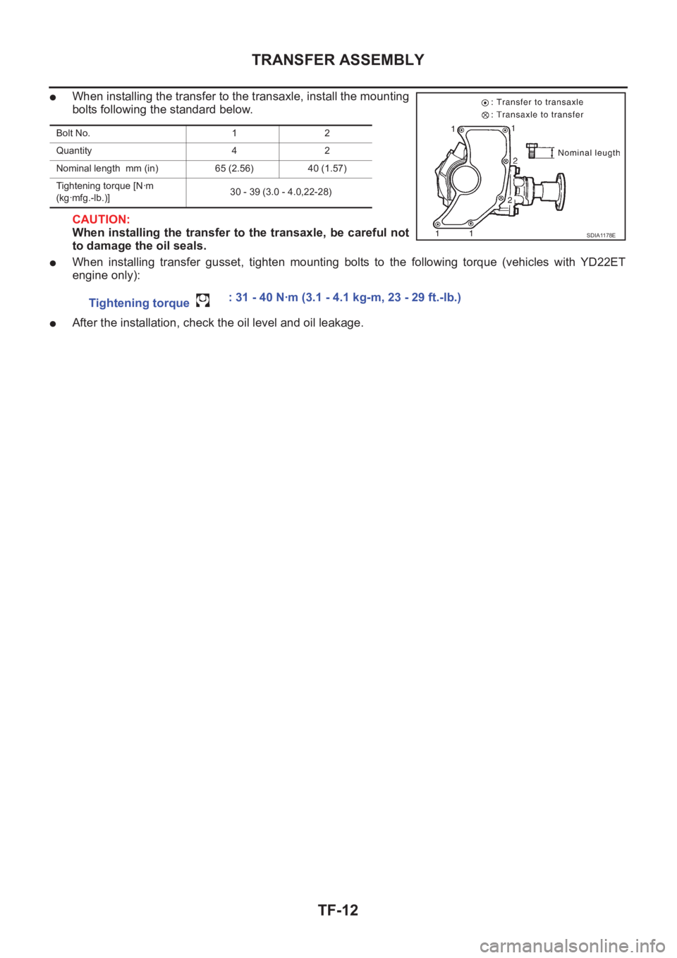
●When installing the transfer to the transaxle, install the mounting
bolts following the standard below.
CAUTION:
When installing the transfer to the transaxle, be careful not
to damage the oil seals.
●When installing transfer gusset, tighten mounting bolts to the following torque (vehicles with YD22ET
engine only):
●After the installation, check the oil level and oil leakage.
Bolt No. 1 2
Quantity 4 2
Nominal length mm (in) 65 (2.56) 40 (1.57)
Tightening torque [N·m
(kg·mfg.-lb.)]30 - 39 (3.0 - 4.0,22-28)
SDIA1178E
Tightening torque : 31 - 40 N·m (3.1 - 4.1 kg-m, 23 - 29 ft.-lb.)
Page 2641 of 3833
ALL MODE 4X4 SYSTEM
TF-31
C
E
F
G
H
I
J
K
L
MA
B
TF
4WD MODE SWITCH
AUTO mode (AUTO indicator lamp ON)
●Electronic control allows optimal distribution of torque to front/rear wheels to match road conditions.
●Makes possible stable driving, with no wheel spin, on snowy roads or other slippery surfaces.
●On roads which do not require 4WD, it contributes to improved fuel economy by driving in conditions close
to front-wheel drive.
●Sensors determine the vehicle's turning condition, and in response tight cornering/braking are controlled
by distributing optimum torque to rear wheels.
NOTE:
●When driving in AUTO mode or LOCK mode, if there is a large difference between front and rear wheel
speed which continues for a long time, oil temperature of drive system parts becomes too high and 4WD
warning lamp flashes rapidly. (When 4WD warning lamp flashes, vehicle changes to front-wheel drive
conditions.)
● When driving in AUTO mode, 4WD warning lamp may flash slowly if there is a significant difference in
pressure or wear between tires. At this time, vehicle performance is not fully available and cautious driving
is required. (Continues until engine is turned OFF.)
●If 4WD warning lamp is flashing rapidly, stop vehicle and allow it to idle for some time. Flashing will stop
and AUTO mode will be restored.
●If the warning lamp flashes slowly during driving but remains OFF after engine is restarted, the system is
normal. If it again flashes slowly after driving for some time, vehicle must be inspected.
●When the difference of revolution speed between the front and rear wheel with AUTO mode the shift
switch occasionally changes to LOCK mode automatically. This is not malfunction.
LOCK mode (LOCK indicator lamp and AUTO indicator lamp ON)
●Front/rear wheel torque distribution is fixed, ensuring stable driving when climbing slopes.
●When LOCK mode is selected, vehicle will switch automatically to AUTO mode if vehicle speed increases.
If vehicle speed then decreases, the vehicle automatically returns to direct 4-wheel driving conditions.
NOTE:
If there is a significant difference in pressure or wear between tires, full vehicle performance is not available.
Tire conditions are detected, and LOCK mode may be prohibited, or else speeds at which LOCK mode is
enabled may be restricted.
2WD mode (indicator lamps OFF)
Vehicle is in front-wheel drive.
NOTE:
● If front wheels are slipping in 2WD mode, do not switch to AUTO or LOCK. This can cause difficulties for
the system.
● The shift switch even if the shift switch is in 2WD mode, the sift switch occasionally automatically change
to 4WD mode depending on the driving condition (For example; Depressing the acceleration firmly). this is
not malfunction. How ever, 4WD mode indicator lamp dose not illuminate.
4WD WARNING LAMP
Turns ON when there is a malfunction in 4WD system. It indicates that fail-safe mode is engaged and vehicle
is in 2WD.
Also turns ON when ignition switch is turned ON, for purpose of bulb check. Turns OFF approximately for 3
seconds after the engine starts if system is normal.
4WD waning lamp indiction
Condition Display 4WD warning lamp
Self-diagnosisWhen self-diagnosis is performed, indicates location of
malfunction by number of flashes.-
Lamp checkTurns ON when engine is started to check for burned-out
lamps.Turns ON when ignition switch
is turned ON. Turns OFF
approximately 3 seconds after
engine start.
4WD system malfunction Turns ON if there is malfunction in 4WD system. ON
Page 2678 of 3833
RFD-2
PRECAUTIONS
PRECAUTIONS
PFP:00001
CautionEDS00101
●Before starting diagnosis of the vehicle, understand symptoms well. Perform correct and systematic oper-
ations.
●Check for the correct installation status prior to removal or disassembly. When mating marks are required,
be sure they do not interfere with the function of the parts they are applied to.
●Carry out an overhaul in a clean work place. Using a dust proof room is recommended.
●Before disassembly, using steam or white gasoline, completely remove sand and mud from the exterior of
the unit, preventing them from entering into the unit during disassembly or assembly.
●Check appearance of the disassembled parts for damage, deformation, and abnormal wear. If a malfunc-
tion is detected, replace it with a new one.
●Normally replace lock pins, oil seals, and bearings with new ones every time they are removed.
●In principle, tighten bolts or nuts gradually in several steps working diagonally from inside to outside. If
tightening sequence is specified, observe it.
●Clean and flush the parts sufficiently and blow them dry.
●Be careful not to damage the sliding surfaces and mating surfaces.
●When applying sealant, remove the old sealant from the mounting surface; then remove any moisture, oil,
and foreign materials from the application and mounting surfaces.
●Always use shop paper for cleaning the inside of components.
●Avoid using cotton gloves or a shop cloth to prevent entering of lint.
●During assembly, observe the specified tightening torque, and apply new differential oil, Vaseline, or Nis-
san MP Special Grease No. 2, as specified for each vehicle, when necessary.
●Do not reuse drained oil. Discard waste oil after oil changes or part treatment in accordance with local
laws and regulations.
Precautions for Brake SystemEDS00102
●When installing rubber parts, final tightening must be carried out under unladen condition* with tires on
ground.
*: Fuel, radiator coolant and engine oil full. Spare tire, jack, hand tools and mats in designated positions.
●After installing removed suspension parts, check wheel alignment and adjust if necessary.
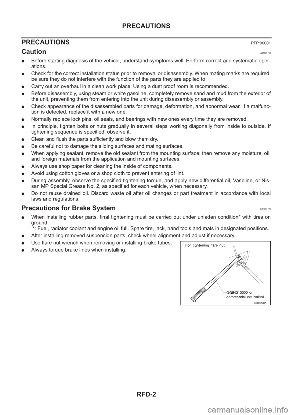
●Use flare nut wrench when removing or installing brake tubes.
●Always torque brake lines when installing.
SBR820BA
Page 2719 of 3833
SERVICE DATA AND SPECIFICATIONS (SDS)
FSU-13
C
D
F
G
H
I
J
K
L
MA
B
FSU
SERVICE DATA AND SPECIFICATIONS (SDS)PFP:00030
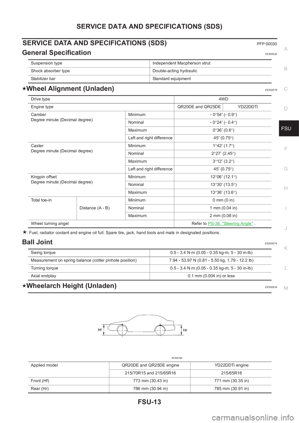
General SpecificationEES000J6
Wheel Alignment (Unladen)EES00079
: Fuel, radiator coolant and engine oil full. Spare tire, jack, hand tools and mats in designated positions.
Ball JointEES0007A
Wheelarch Height (Unladen)EES000J9
Suspension type Independent Macpherson strut
Shock absorber type Double-acting hydraulic
Stabilizer bar Standard equipment
Drive type4WD
Engine type QR20DE and QR25DE YD22DDTi
Camber
Degree minute (Decimal degree)Minimum - 0°54′ (- 0.9°)
Nominal - 0°24′ (- 0.4°)
Maximum 0°36′ (0.6°)
Left and right difference 45′ (0.75°)
Caster
Degree minute (Decimal degree)Minimum 1°42′ (1.7°)
Nominal 2°27′ (2.45°)
Maximum 3°12′ (3.2°)
Left and right difference 45′ (0.75°)
Kingpin offset
Degree minute (Decimal degree)Minimum 12°06′ (12.1°)
Nominal 13°30′ (13.5°)
Maximum 13°36′ (13.6°)
Total toe-in
Distance (A - B)Minimum 0 mm (0 in)
Nominal 1 mm (0.04 in)
Maximum 2 mm (0.08 in)
Wheel turning angel Refer to PS-36, "
Steering Angle" .
Swing torque 0.5 - 3.4 N·m (0.05 - 0.35 kg-m, 5 - 30 in-lb)
Measurement on spring balance (cotter pinhole position) 7.94 - 53.97 N (0.81 - 5.50 kg, 1.79 - 12.2 lb)
Turning torque 0.5 - 3.4 N·m (0.05 - 0.35 kg-m, 5 - 30 in-lb)
Axial endplay 0.1 mm (0.004 in) or less
Applied model QR20DE and QR25DE engine YD22DDTi engine
215/70R15 and 215/65R16 215/65R16
Front (Hf) 773 mm (30.43 in) 771 mm (30.35 in)
Rear (Hr) 786 mm (30.94 in) 785 mm (30.91 in)
SFA818A
Page 2720 of 3833

FSU-14
SERVICE DATA AND SPECIFICATIONS (SDS)
: Fuel, radiator coolant and engine oil full. Spare tire, jack, hand tools and mats in designated positions.
Page 2734 of 3833
RSU-14
SERVICE DATA AND SPECIFICATIONS (SDS)
SERVICE DATA AND SPECIFICATIONS (SDS)
PFP:00030
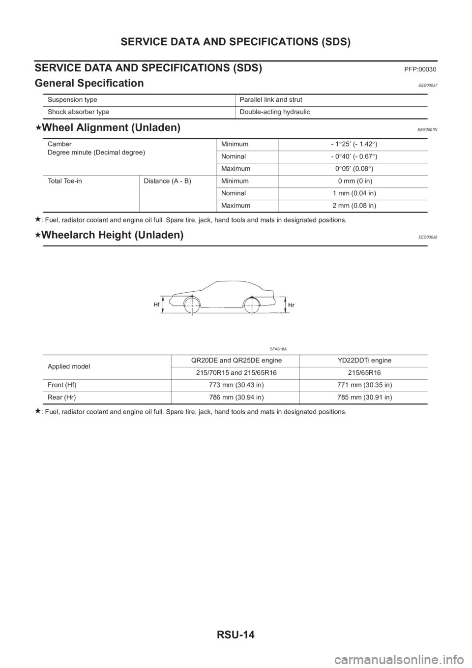
General SpecificationEES000J7
Wheel Alignment (Unladen)EES0007N
: Fuel, radiator coolant and engine oil full. Spare tire, jack, hand tools and mats in designated positions.
Wheelarch Height (Unladen)EES000J8
: Fuel, radiator coolant and engine oil full. Spare tire, jack, hand tools and mats in designated positions. Suspension type Parallel link and strut
Shock absorber type Double-acting hydraulic
Camber
Degree minute (Decimal degree)Minimum - 1°25′ (- 1.42°)
Nominal - 0°40′ (- 0.67°)
Maximum 0°05′ (0.08°)
Total Toe-in Distance (A - B) Minimum 0 mm (0 in)
Nominal 1 mm (0.04 in)
Maximum 2 mm (0.08 in)
Applied modelQR20DE and QR25DE engine YD22DDTi engine
215/70R15 and 215/65R16 215/65R16
Front (Hf) 773 mm (30.43 in) 771 mm (30.35 in)
Rear (Hr) 786 mm (30.94 in) 785 mm (30.91 in)
SFA818A