Page 3206 of 3833
GW-54
DOOR MIRROR
Removal and Installation
EIS004JR
REMOVAL
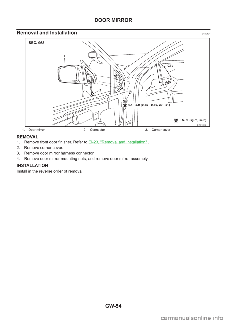
1. Remove front door finisher. Refer to EI-23, "Removal and Installation" .
2. Remove corner cover.
3. Remove door mirror harness connector.
4. Remove door mirror mounting nuts, and remove door mirror assembly.
INSTALLATION
Install in the reverse order of removal.
1. Door mirror 2. Connector 3. Corner cover
SIIA0186E
Page 3207 of 3833
DOOR MIRROR
GW-55
C
D
E
F
G
H
J
K
L
MA
B
GW
Disassembly and AssemblyEIS004JS
DISASSEMBLY
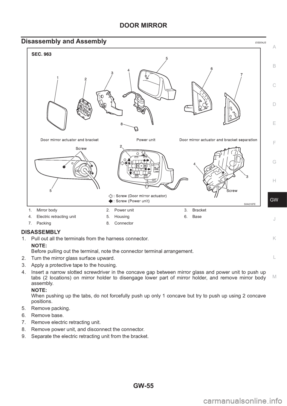
1. Pull out all the terminals from the harness connector.
NOTE:
Before pulling out the terminal, note the connector terminal arrangement.
2. Turn the mirror glass surface upward.
3. Apply a protective tape to the housing.
4. Insert a narrow slotted screwdriver in the concave gap between mirror glass and power unit to push up
tabs (2 locations) on mirror holder to disengage lower part of mirror holder, and remove mirror body
assembly.
NOTE:
When pushing up the tabs, do not forcefully push up only 1 concave but try to push up using 2 concave
positions.
5. Remove packing.
6. Remove base.
7. Remove electric retracting unit.
8. Remove power unit, and disconnect the connector.
9. Separate the electric retracting unit from the bracket.
1. Mirror body 2. Power unit 3. Bracket
4. Electric retracting unit 5. Housing 6. Base
7. Packing 8. Connector
SIIA0187E
Page 3208 of 3833
GW-56
DOOR MIRROR
ASSEMBLY
1. Install bracket to the electric retracting unit.
2. Connect power unit connector. Install electric retracting unit (bracket).
3. Install electric retracting unit and base to the housing.
4. Place power unit and mirror body assembly in a horizontal position.
5. Engage upper tabs of mirror glass with power unit. Then, press lower part of mirror glass down until the
lower part snaps to allow engagement of lower tabs.
NOTE:
After installation, visually check that the lower tabs (2) are securely engaged when viewed from the bot-
tom of mirror surface.
6. Install the packing to the base.
7. Insert the harness terminal into the connector.
NOTE:
Make sure to insert the harness terminal into the correct connector. Do not confuse the locations.
Page 3234 of 3833
EI-14
DOOR OUTSIDE MOLDING
DOOR OUTSIDE MOLDING
PFP:82820
Removal and InstallationEIS0015E
REMOVAL
Front
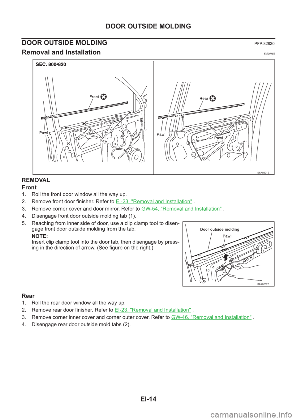
1. Roll the front door window all the way up.
2. Remove front door finisher. Refer to EI-23, "
Removal and Installation" .
3. Remove corner cover and door mirror. Refer to GW-54, "
Removal and Installation" .
4. Disengage front door outside molding tab (1).
5. Reaching from inner side of door, use a clip clamp tool to disen-
gage front door outside molding from the tab.
NOTE:
Insert clip clamp tool into the door tab, then disengage by press-
ing in the direction of arrow. (See figure on the right.)
Rear
1. Roll the rear door window all the way up.
2. Remove rear door finisher. Refer to EI-23, "
Removal and Installation" .
3. Remove corner inner cover and corner outer cover. Refer to GW-46, "
Removal and Installation" .
4. Disengage rear door outside mold tabs (2).
SIIA0201E
SIIA0202E
Page 3249 of 3833
HEADLINING
EI-29
C
D
E
F
G
H
J
K
L
MA
B
EI
HEADLININGPFP:73910
Removal and InstallationEIS000ND
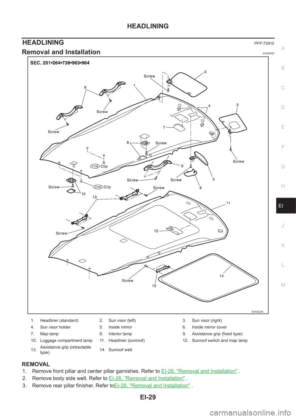
REMOVAL
1. Remove front pillar and center pillar garnishes. Refer to EI-26, "Removal and Installation" .
2. Remove body side welt. Refer to EI-26, "
Removal and Installation" .
3. Remove rear pillar finisher. Refer toEI-26, "
Removal and Installation" .
SIIA0223E
1. Headliner (standard) 2. Sun visor (left) 3. Sun visor (right)
4. Sun visor holder 5. Inside mirror 6. Inside mirror cover
7. Map lamp 8. Interior lamp 9. Assistance grip (fixed type)
10. Luggage compartment lamp 11. Headliner (sunroof) 12. Sunroof switch and map lamp
13.Assistance grip (retractable
type)14. Sunroof welt
Page 3250 of 3833
EI-30
HEADLINING
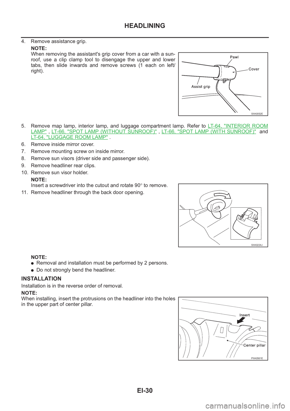
4. Remove assistance grip.
NOTE:
When removing the assistant's grip cover from a car with a sun-
roof, use a clip clamp tool to disengage the upper and lower
tabs, then slide inwards and remove screws (1 each on left/
right).
5. Remove map lamp, interior lamp, and luggage compartment lamp. Refer to LT- 6 4 , "
INTERIOR ROOM
LAMP" , LT- 6 6 , "SPOT LAMP (WITHOUT SUNROOF)" , LT- 6 6 , "SPOT LAMP (WITH SUNROOF)" and
LT- 6 4 , "
LUGGAGE ROOM LAMP" .
6. Remove inside mirror cover.
7. Remove mounting screw on inside mirror.
8. Remove sun visors (driver side and passenger side).
9. Remove headliner rear clips.
10. Remove sun visor holder.
NOTE:
Insert a screwdriver into the cutout and rotate 90° to remove.
11. Remove headliner through the back door opening.
NOTE:
●Removal and installation must be performed by 2 persons.
●Do not strongly bend the headliner.
INSTALLATION
Installation is in the reverse order of removal.
NOTE:
When installing, insert the protrusions on the headliner into the holes
in the upper part of center pillar.
SIIA0052E
SIIA0224J
PIIA0561E
Page 3251 of 3833
IP-1
INSTRUMENT PANEL
I BODY
CONTENTS
C
D
E
F
G
H
J
K
L
M
SECTION
A
B
IP
INSTRUMENT PANEL
PRECAUTIONS .......................................................... 2
Precautions for Supplemental Restraint System
(SRS) “AIR BAG” and “SEAT BELT PRE-TEN-
SIONER” .................................................................. 2
Precautions .............................................................. 2
INSTRUMENT PANEL ASSEMBLY ........................... 3
Component Parts Drawing ....................................... 3
Removal and Installation .......................................... 5
TABLE OF WORK ITEM ....................................... 5
FRONT SPEAKER GRILLE .................................. 6
INSTRUMENT FINISHER ..................................... 6
CUP HOLDER ....................................................... 6
CLUSTER LID A ................................................... 6
COMBINATION METER ....................................... 6
POCKET ............................................................... 6
STEERING COLUMN COVER ............................. 6
INSTRUMENT LOWER DRIVER PANEL ............. 7
MIRROR CONTROL SWITCH .............................. 7
GPS ANTENNA .................................................... 7
CLUSTER LID C ................................................... 7CLUSTER LID FINISHER ..................................... 7
AUDIO UNIT AND POCKET ................................. 7
HEATER CONTROL FINISHER ............................ 8
CD AUTO–CHANGER AND POCKET .................. 8
HEATER CONTROLLER ....................................... 8
A/T OR M/T FINISHER ......................................... 8
CONSOLE MASK AND CENTER CONSOLE ....... 8
LOWER INSTRUMENT COVER ........................... 8
INSTRUMENT LOWER CENTER PANEL ............ 8
GLOVE BOX ......................................................... 9
LOWER INSTRUMENT PANEL ............................ 9
GLOVE BOX COVER ............................................ 9
FRONT PASSENGER AIR BAG MODULE ........... 9
INSTRUMENT REINFORCEMENT ....................... 9
INSTRUMENT MASK ............................................ 9
FRONT PILLAR GARNISH ................................... 9
INSTRUMENT PANEL .......................................... 9
Disassembly and Assembly .................................... 10
CONSOLE BOX ASSEMBLY .............................. 10
Page 3254 of 3833
IP-4
INSTRUMENT PANEL ASSEMBLY
1. Front passenger air bag module 2. Front speaker grille (right) 3. Front side speaker (right)
4. Cup holder (right) 5. Instrument finisher B 6. Combination meter
7. Instrument mask (right) 8. GPS antenna 9. Instrument mask (left)
10. Instrument cluster lid A 11. Pocket 12. Front speaker grille (left)
13. Front side speaker (left) 14. Cup holder (left) 15. Mirror control switch
16. Instrument panel & pad 17. Instrument reinforcement 18. Audio unit and pocket
19. Glove box cover 20. Lower instrument panel 21. Glove box pin
22. Glove box 23. Cluster lid C 24. Instrument finisher A
25. Instrument lower driver panel 26. Column cover, key cylinder escutcheon 27. Cluster lid finisher (left)
28. Heater control finisher 29. CD auto–changer and pocket 30. instrument lower center panel
31. Lower instrument cover 32. Cluster lid finisher (right) 33. Center console
34. A/T or M/T finisher 35. Console mask 36. Seal case (inner case)