2001 NISSAN X-TRAIL mirror
[x] Cancel search: mirrorPage 3255 of 3833
![NISSAN X-TRAIL 2001 Service Repair Manual INSTRUMENT PANEL ASSEMBLY
IP-5
C
D
E
F
G
H
J
K
L
MA
B
IP
Removal and InstallationEIS000NI
TABLE OF WORK ITEM
[ ]: The number shows the removal order.
ComponentsInstrument
panelCombination
meterNavig](/manual-img/5/57405/w960_57405-3254.png "NISSAN X-TRAIL 2001 Service Repair Manual INSTRUMENT PANEL ASSEMBLY
IP-5
C
D
E
F
G
H
J
K
L
MA
B
IP
Removal and InstallationEIS000NI
TABLE OF WORK ITEM
[ ]: The number shows the removal order.
ComponentsInstrument
panelCombination
meterNavig")
INSTRUMENT PANEL ASSEMBLY
IP-5
C
D
E
F
G
H
J
K
L
MA
B
IP
Removal and InstallationEIS000NI
TABLE OF WORK ITEM
[ ]: The number shows the removal order.
ComponentsInstrument
panelCombination
meterNavigation
DisplayAudio
Console
Up Down
Front speaker grille [1]
Instrument finisher A, B [2] [1]
Cup holder [3]
Instrument cluster lid A [4] [2]
Combination meter [5] [3]
Pocket [6]
Key cylinder escutcheon and steer-
ing column cover[7]
Instrument lower driver panel [8]
Mirror control switch [9]
GPS antenna [10]
Cluster lid C [11] [1] [1]
Cluster lid finisher [12] [1] [1]
Audio unit and pocket [13] [2] [2]
Heater control finisher [14] [2]
CD auto–changer and pocket [15] [3]
Heater controller [16]
A/T(M/T,CVT) finisher [17] [2]
Console mask [18] [3]
Center console [19] [4]
Lower instrument cover [20]
instrument lower center panel [21]
Glove box [22]
Lower instrument panel [23]
Glove box cover [24]
Front passenger air bag module [25]
Instrument reinforcement [26]
Instrument mask [27]
Front pillar garnish [28]
Instrument panel [29]
Page 3257 of 3833
INSTRUMENT PANEL ASSEMBLY
IP-7
C
D
E
F
G
H
J
K
L
MA
B
IP
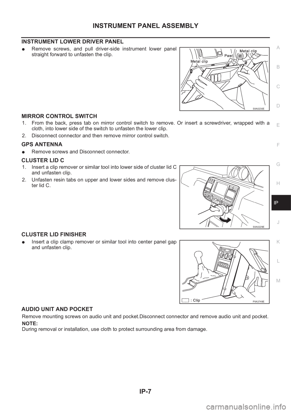
INSTRUMENT LOWER DRIVER PANEL
●Remove screws, and pull driver-side instrument lower panel
straight forward to unfasten the clip.
MIRROR CONTROL SWITCH
1. From the back, press tab on mirror control switch to remove. Or insert a screwdriver, wrapped with a
cloth, into lower side of the switch to unfasten the lower clip.
2. Disconnect connector and then remove mirror control switch.
GPS ANTENNA
●Remove screws and Disconnect connector.
CLUSTER LID C
1. Insert a clip remover or similar tool into lower side of cluster lid C
and unfasten clip.
2. Unfasten resin tabs on upper and lower sides and remove clus-
ter lid C.
CLUSTER LID FINISHER
●Insert a clip clamp remover or similar tool into center panel gap
and unfasten clip.
AUDIO UNIT AND POCKET
Remove mounting screws on audio unit and pocket.Disconnect connector and remove audio unit and pocket.
NOTE:
During removal or installation, use cloth to protect surrounding area from damage.
SIIA0230E
SIIA0229E
PIIA3749E
Page 3423 of 3833
REFRIGERANT LINES
ATC-147
C
D
E
F
G
H
I
K
L
MA
B
AT C
Checking System for Leaks Using the Fluorescent Leak DetectorEJS000VK
1. Check A/C system for leaks using the UV lamp and safety goggles (J-42220) in a low sunlight area (area
without windows preferable). Illuminate all components, fittings and lines. The dye will appear as a bright
green/yellow area at the point of leakage. Fluorescent dye observed at the evaporator drain opening indi-
cates an evaporator core assembly (tubes, core or expansion valve) leak.
2. If the suspected area is difficult to see, use an adjustable mirror or wipe the area with a clean shop rag or
cloth, with the UV lamp for dye residue.
3. After the leak is repaired, remove any residual dye using dye cleaner (J-43872) to prevent future misdiag-
nosis.
4. Perform a system performance check and verify the leak repair with an approved electronic refrigerant
leak detector.
NOTE:
Other gases in the work area or substances on the A/C components, for example, anti-freeze, windshield
washer fluid, solvents and lubricants, may falsely trigger the leak detector. Make sure the surfaces to be
checked are clean.
Clean with a dry cloth or blow off with shop air.
Do not allow the sensor tip of the detector to contact with any substance. This can also cause false readings
and may damage the detector.
Dye InjectionEJS000VL
(This procedure is only necessary when recharging the system or when the compressor has seized and was
replaced.)
1. Check A/C system static (at rest) pressure. Pressure must be at least 345 kPa (50 psi).
2. Pour one bottle (1/4 ounce / 7.4 cc) of the A/C refrigerant dye into the injector tool (J-41459).
3. Connect the injector tool to the A/C LOW PRESSURE side service fitting.
4. Start engine and switch A/C ON.
5. When the A/C operating (compressor running), inject one bottle (1/4 ounce / 7.4 cc) of fluorescent dye
through the low-pressure service valve using dye injector tool J-41459 (refer to the manufacture's operat-
ing instructions).
6. With the engine still running, disconnect the injector tool from the service fitting.
CAUTION:
Be careful the A/C system or replacing a component, pour the dye directly into the open system con-
nection and proceed with the service procedures.
7. Operate the A/C system for a minimum of 20 minutes to mix the dye with the system oil. Depending on the
leak size, operating conditions and location of the leak, it may take from minutes to days for the dye to
penetrate a leak and become visible.
Electronic Refrigerant Leak DetectorEJS000VM
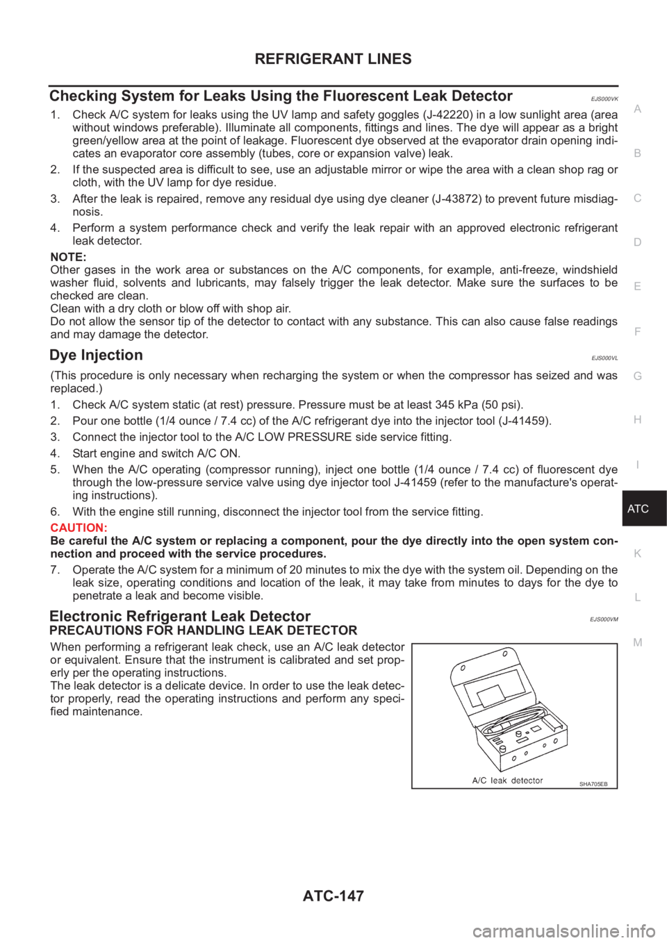
PRECAUTIONS FOR HANDLING LEAK DETECTOR
When performing a refrigerant leak check, use an A/C leak detector
or equivalent. Ensure that the instrument is calibrated and set prop-
erly per the operating instructions.
The leak detector is a delicate device. In order to use the leak detec-
tor properly, read the operating instructions and perform any speci-
fied maintenance.
SHA705EB
Page 3535 of 3833
![NISSAN X-TRAIL 2001 Service Repair Manual ILLUMINATION
LT-45
C
D
E
F
G
H
I
J
L
MA
B
LT
ILLUMINATIONPFP:27545
System Description EKS003C7
Power is supplied at all times
●through 10A fuse [No. 31, located in the fuse and fusible link box]
●](/manual-img/5/57405/w960_57405-3534.png "NISSAN X-TRAIL 2001 Service Repair Manual ILLUMINATION
LT-45
C
D
E
F
G
H
I
J
L
MA
B
LT
ILLUMINATIONPFP:27545
System Description EKS003C7
Power is supplied at all times
●through 10A fuse [No. 31, located in the fuse and fusible link box]
●")
ILLUMINATION
LT-45
C
D
E
F
G
H
I
J
L
MA
B
LT
ILLUMINATIONPFP:27545
System Description EKS003C7
Power is supplied at all times
●through 10A fuse [No. 31, located in the fuse and fusible link box]
●to lighting switch terminal 11.
The lighting switch must be in the 1ST or 2ND position for illumination.
The following chart shows the power and ground connector terminals for the components included in the illu-
mination system.
Component Connector No. Power terminal Ground terminal
Headlamp washier switch M23 3 4
Headlamp aiming switch M24 3 4
Door mirror remote control
switchM26 10 1
ESP off switch M25 3 4
Hazard switch M51 7 8
4WD mode switch M39 4 3
Rear window defogger switch M50 5 6
A/C auto amp. M52 12 11
Combination meter
(LHD models)M46 56 66
Combination meter
(RHD models)M46 45 56
Audio M42 2 1
CD auto changer M82 34 35
Heater control panel M55 2 6
A/T device M58 3 4
Cigarette lighter M56 3 2
Heated seat switch LH
(LHD models)B131 5 6
Heated seat switch RH
(LHD models)B132 5 6
Heated seat switch LH
(RHD models)B35 5 6
Heated seat switch RH
(RHD models)B34 5 6
Page 3765 of 3833
HARNESS
PG-61
C
D
E
F
G
H
I
J
L
MA
B
PG
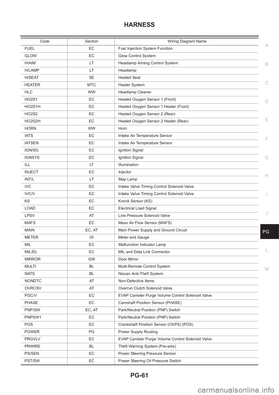
FUEL EC Fuel Injection System Function
GLOW EC Glow Control System
H/AIM LT Headlamp Aiming Control System
H/LAMP LT Headlamp
H/SEAT SE Heated Seat
HEATER MTC Heater System
HLC WW Headlamp Cleaner
HO2S1 EC Heated Oxygen Sensor 1 (Front)
HO2S1H EC Heated Oxygen Sensor 1 Heater (Front)
HO2S2 EC Heated Oxygen Sensor 2 (Rear)
HO2S2H EC Heated Oxygen Sensor 2 Heater (Rear)
HORN WW Horn
IATS EC Intake Air Temperature Sensor
IATSEN EC Intake Air Temperature Sensor
IGN/SG EC Ignition Signal
IGNSYS EC Ignition Signal
ILL LT Illumination
INJECT EC Injector
INT/L LT Map Lamp
IVC EC Intake Valve Timing Control Solenoid Valve
IVC/V EC Intake Valve Timing Control Solenoid Valve
KS EC Knock Sensor (KS)
LOAD EC Electrical Load Signal
LPSV AT Line Pressure Solenoid Valve
MAFS EC Mass Air Flow Sensor (MAFS)
MAIN EC, AT Main Power Supply and Ground Circuit
METER DI Meter and Gauge
MIL EC Malfunction Indicator Lamp
MIL/DL EC MIL and Data Link Connector
MIRROR GW Door Mirror
MULTI BL Multi-Remote Control System
NATS BL Nissan Anti-Theft System
NONDTC AT Non-Detective Items
OVRCSV AT Overrun Clutch Solenoid Valve
PGC/V EC EVAP Canister Purge Volume Control Solenoid Valve
PHASE EC Camshaft Position Sensor (PHASE)
PNP/SW EC, AT Park/Neutral Position (PNP) Switch
PNPSW1 EC Park/Neutral Position (PNP) Switch
POS EC Crankshaft Position Sensor (CKPS) (POS)
POWER PG Power Supply Routing
PRGVLV EC EVAP Canister Purge Volume Control Solenoid Valve
PRWIRE BL Theft Warning System (Pre-wire)
PS/SEN EC Power Steering Pressure Sensor
PST/SW EC Power Steering Oil Pressure SwitchCode Section Wiring Diagram Name
Page 3785 of 3833

DESCRIPTION
MA-5
C
D
E
F
G
H
I
J
K
MA
B
MA
Squeaks and rattles
ENGINE OPERATING AND HOT
Adjust idle speed
Automatic transmission/transaxle fluid level
Engine idling and stop knob operation (Diesel only)
FINAL INSPECTION
Install necessary parts (outside mirror, wheel covers, seat belts, mat, carpet or mud flaps)
Inspect for interior and exterior metal and paint damage
Check for spare tire, jack, tools (wheel chock), and literature
Wash, clean interior and exterior
: Not applicable to this model
Page 3828 of 3833
IDX-4
ALPHABETICAL INDEX
Cylinder head bolt tightening(YD22DDTi) ....... EM-184
Cylinder head gasket selection(YD22DDTi) ... EM-185
Cylinder head(QR20DE•QR25DE) ................... EM-59
Cylinder head(YD22DDTi) .............................. EM-182
D
Data link connector .......... EC-424
,EC-745,EC-1111,
EC-1385
Data link connector for Consult ........... EC-96,EC-488,
EC-827
,EC-1174,EC-1431
Daytime light system ............................................. LT-9
Daytime running light - See Daytime light system LT-9
DEF - Wiring diagram ....................................... GW-15
Desiccant Assembly ....................... ATC-30,ATC-146
Diagnosis sensor unit ..................................... SRS-40
Diagnostic trouble code (DTC) ...................... EC-1406
Diagnostic trouble code (DTC) for OBD system EC-20,
EC-47
,EC-432,EC-454,EC-753,EC-779,EC-1119,
EC-1141
,EC-1393
Diagnostic trouble code (DTC) inspection priority chart
EC-70
,EC-463,EC-802,EC-1150
Differential gear (FF M/T) ..................... MT-21,MT-26
DLC - Wiring diagram ...... EC-424,EC-745,EC-1111,
EC-1385
Door glass ........................................... GW-44,GW-46
Door glass Fitting Adjustment ............. GW-44,GW-46
Door lock ................................................. BL-65,BL-68
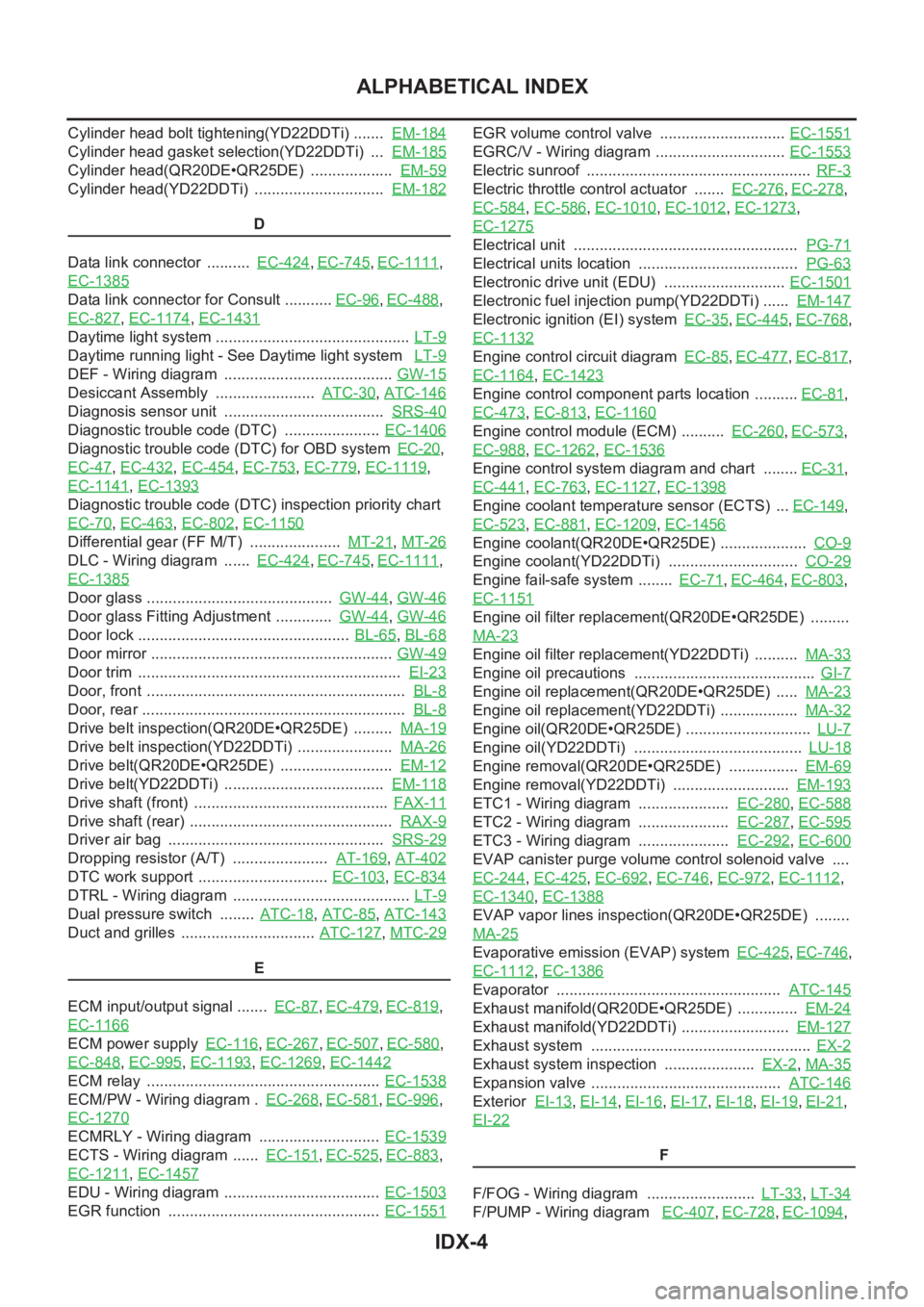
Door mirror ........................................................ GW-49
Door trim ............................................................. EI-23
Door, front ............................................................ BL-8
Door, rear ............................................................. BL-8
Drive belt inspection(QR20DE•QR25DE) ......... MA-19
Drive belt inspection(YD22DDTi) ...................... MA-26
Drive belt(QR20DE•QR25DE) .......................... EM-12
Drive belt(YD22DDTi) ..................................... EM-118
Drive shaft (front) ............................................. FAX-11
Drive shaft (rear) ............................................... RAX-9
Driver air bag .................................................. SRS-29
Dropping resistor (A/T) ...................... AT-169,AT-402
DTC work support .............................. EC-103,EC-834
DTRL - Wiring diagram ......................................... LT-9
Dual pressure switch ........ ATC-18,ATC-85,ATC-143
Duct and grilles ............................... ATC-127,MTC-29
E
ECM input/output signal ....... EC-87
,EC-479,EC-819,
EC-1166
ECM power supply EC-116,EC-267,EC-507,EC-580,
EC-848
,EC-995,EC-1193,EC-1269,EC-1442
ECM relay ...................................................... EC-1538
ECM/PW - Wiring diagram . EC-268,EC-581,EC-996,
EC-1270
ECMRLY - Wiring diagram ............................ EC-1539
ECTS - Wiring diagram ...... EC-151,EC-525,EC-883,
EC-1211
,EC-1457
EDU - Wiring diagram .................................... EC-1503
EGR function ................................................. EC-1551
EGR volume control valve ............................. EC-1551
EGRC/V - Wiring diagram .............................. EC-1553
Electric sunroof .................................................... RF-3
Electric throttle control actuator ....... EC-276,EC-278,
EC-584
,EC-586,EC-1010,EC-1012,EC-1273,
EC-1275
Electrical unit .................................................... PG-71
Electrical units location ..................................... PG-63
Electronic drive unit (EDU) ............................ EC-1501
Electronic fuel injection pump(YD22DDTi) ...... EM-147
Electronic ignition (EI) system EC-35,EC-445,EC-768,
EC-1132
Engine control circuit diagram EC-85,EC-477,EC-817,
EC-1164
,EC-1423
Engine control component parts location .......... EC-81,
EC-473
,EC-813,EC-1160
Engine control module (ECM) .......... EC-260,EC-573,
EC-988
,EC-1262,EC-1536
Engine control system diagram and chart ........ EC-31,
EC-441
,EC-763,EC-1127,EC-1398
Engine coolant temperature sensor (ECTS) ... EC-149,
EC-523
,EC-881,EC-1209,EC-1456
Engine coolant(QR20DE•QR25DE) .................... CO-9
Engine coolant(YD22DDTi) .............................. CO-29
Engine fail-safe system ........ EC-71,EC-464,EC-803,
EC-1151
Engine oil filter replacement(QR20DE•QR25DE) .........
MA-23
Engine oil filter replacement(YD22DDTi) .......... MA-33
Engine oil precautions .......................................... GI-7
Engine oil replacement(QR20DE•QR25DE) ..... MA-23
Engine oil replacement(YD22DDTi) .................. MA-32
Engine oil(QR20DE•QR25DE) ............................. LU-7
Engine oil(YD22DDTi) ....................................... LU-18
Engine removal(QR20DE•QR25DE) ................ EM-69
Engine removal(YD22DDTi) ........................... EM-193
ETC1 - Wiring diagram ..................... EC-280,EC-588
ETC2 - Wiring diagram ..................... EC-287,EC-595
ETC3 - Wiring diagram ..................... EC-292,EC-600
EVAP canister purge volume control solenoid valve ....
EC-244
,EC-425,EC-692,EC-746,EC-972,EC-1112,
EC-1340
,EC-1388
EVAP vapor lines inspection(QR20DE•QR25DE) ........
MA-25
Evaporative emission (EVAP) system EC-425,EC-746,
EC-1112
,EC-1386
Evaporator .................................................... ATC-145
Exhaust manifold(QR20DE•QR25DE) .............. EM-24
Exhaust manifold(YD22DDTi) ......................... EM-127
Exhaust system ................................................... EX-2
Exhaust system inspection ..................... EX-2,MA-35
Expansion valve ............................................ ATC-146
Exterior EI-13,EI-14,EI-16,EI-17,EI-18,EI-19,EI-21,
EI-22
F
F/FOG - Wiring diagram ......................... LT-33
,LT-34
F/PUMP - Wiring diagram EC-407,EC-728,EC-1094,
Page 3829 of 3833
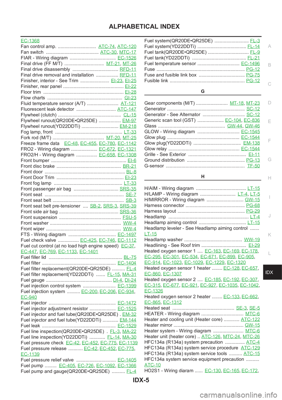
IDX-5
A
C
D
E
F
G
H
I
J
K
L B
IDX
ALPHABETICAL INDEX
EC-1368
Fan control amp. ............................. ATC-74,ATC-120
Fan switch ........................................ ATC-30,MTC-17
FIAR - Wiring diagram ................................... EC-1526
Final drive (FF M/T) .............................. MT-21,MT-26
Final drive disassembly ................................... RFD-11
Final drive removal and installation ................. RFD-11
Finisher, interior - See Trim ...................... EI-23,EI-25
Finisher, rear panel .............................................. EI-22
Floor trim ............................................................. EI-28
Flow charts ......................................................... GI-23
Fluid temperature sensor (A/T) ........................ AT-121
Fluorescent leak detector .............................. ATC-147
Flywheel (clutch) ................................................ CL-15
Flywheel runout(QR20DE•QR25DE) ................. EM-97
Flywheel runout(YD22DDTi) ............................ EM-218
Fog lamp, front ................................................... LT-33
Fork rod (M/T) ....................................... MT-20,MT-25
Freeze frame data EC-48,EC-455,EC-780,EC-1142
FRO2 - Wiring diagram .................... EC-672,EC-1321
FRO2/H - Wiring diagram ................ EC-658,EC-1308
Front bumper ......................................................... EI-6
Front disc brake ................................................. BR-21
Front door ............................................................. BL-8
Front Door Trim ................................................... EI-23
Front fog lamp .................................................... LT-33
Front passenger air bag .................................. SRS-35
Front seat ............................................................ SE-7
Front seat belt ...................................................... SB-3
Front seat belt pre-tensioner .... SB-2,SRS-3,SRS-39
Front side air bag ............................................. SRS-36
Front suspension ............................................... FSU-5
Front washer ...................................................... WW-4
Front wiper ......................................................... WW-4
FTS - Wiring diagram .................................... EC-1497
Fuel check valve ................ EC-425,EC-746,EC-1112
Fuel cut control (at no load high engine speed) EC-37,
EC-447
,EC-769,EC-1133,EC-1401
Fuel filler lid ........................................................ BL-75
Fuel filter ........................................................ EC-1404
Fuel filter replacement(QR20DE•QR25DE) .......... FL-4
Fuel filter replacement(YD22DDTi) ....... FL-15,MA-31
Fuel gauge .................................................. DI-4,DI-24
Fuel injection control system ......................... EC-1399
Fuel injection system .......... EC-200,EC-206,EC-934,
EC-940
Fuel injector ................................................... EC-1472
Fuel injector adjustment resistor .................... EC-1525
Fuel injector and fuel tube(QR20DE•QR25DE) . EM-32
Fuel injector and fuel tube(YD22DDTi) ............ EM-144
Fuel leak ........................................................ EC-1529
Fuel line inspection(QR20DE•QR25DE) . FL-3,MA-22
Fuel line inspection(YD22DDTi) ............ FL-14,MA-30
Fuel pressure check EC-42,EC-452,EC-775,EC-1139
Fuel pressure release ........... EC-42,EC-452,EC-775,
EC-1139
Fuel pressure relief valve .............................. EC-1405
Fuel pump ......... EC-405,EC-726,EC-1092,EC-1366
Fuel pump and gauge(QR20DE•QR25DE) .......... FL-4
Fuel system(QR20DE•QR25DE) .......................... FL-3
Fuel system(YD22DDTi) ..................................... FL-14
Fuel tank(QR20DE•QR25DE) ............................... FL-9
Fuel tank(YD22DDTi) ......................................... FL-21
Fuel temperature sensor ................................ EC-1496
Fuse ................................................................... PG-12
Fuse and fusible link box ................................... PG-75
Fusible link ......................................................... PG-12
G
Gear components (M/T) ........................ MT-18
,MT-23
Generator ........................................................... SC-12
Generator - See Alternator ................................ SC-12
Generic scan tool (GST) .................... EC-104,EC-836
Glass ................................................... GW-44,GW-46
GLOW - Wiring diagram ................................ EC-1545
Glow plug ....................................................... EC-1544
Glow plug(YD22DDTi) .................................... EM-138
Glow relay ...................................................... EC-1544
Grille - See Exterior ............................................ EI-11
Ground distribution ............................................ PG-13
G-sensor ............................................................ TF-50
H
H/AIM - Wiring diagram ...................................... LT-15
H/LAMP - Wiring diagram ........................... LT-4,LT-5
H/MIRROR - Wiring diagram ............................ GW-15
Harness connector ............................................. PG-68
Harness layout ................................................... PG-29
Headlamp ............................................................. LT-4
Headlamp aiming control .................................... LT-15
Headlamp leveler - See Headlamp aiming control .......
LT-15
Headlamp washer ............................................ WW-19
Headlining - See Roof trim .................................. EI-29
Heated oxygen sensor 1 .... EC-163,EC-169,EC-178,
EC-295
,EC-301,EC-534,EC-671,EC-899,EC-905,
EC-914
,EC-1023,EC-1029,EC-1229,EC-1320
Heated oxygen sensor 1 heater ........ EC-128,EC-657,
EC-860
,EC-1307
Heated oxygen sensor 2 .... EC-185,EC-192,EC-307,
EC-315
,EC-677,EC-921,EC-927,EC-1035,EC-1042,
EC-1326
Heated oxygen sensor 2 heater ........ EC-133,EC-662,
EC-865
,EC-1312
Heated seat ............................................... SE-3,SE-5
HEATER - Wiring diagram ................................ MTC-6
Heater and cooling unit (Heater core) ............ ATC-122
Heater mirror ..................................................... GW-15
Heater system - Wiring diagram ....................... MTC-6
Heater unit (heater core) .. ATC-126,MTC-24,MTC-26
HFC134a (R134a) system precaution ............... ATC-4
HFC134a (R134a) system service procedure ATC-129
HFC134a (R134a) system service tools .......... ATC-15
HFC134a system service equipment precaution ..........
ATC-10
HO2S1 - Wiring diaram ...... EC-130,EC-165,EC-172,