2001 NISSAN X-TRAIL fuse box
[x] Cancel search: fuse boxPage 3112 of 3833
BL-60
MULTI-REMOTE CONTROL SYSTEM
Power Supply and Ground Circuit Check
EIS001T4
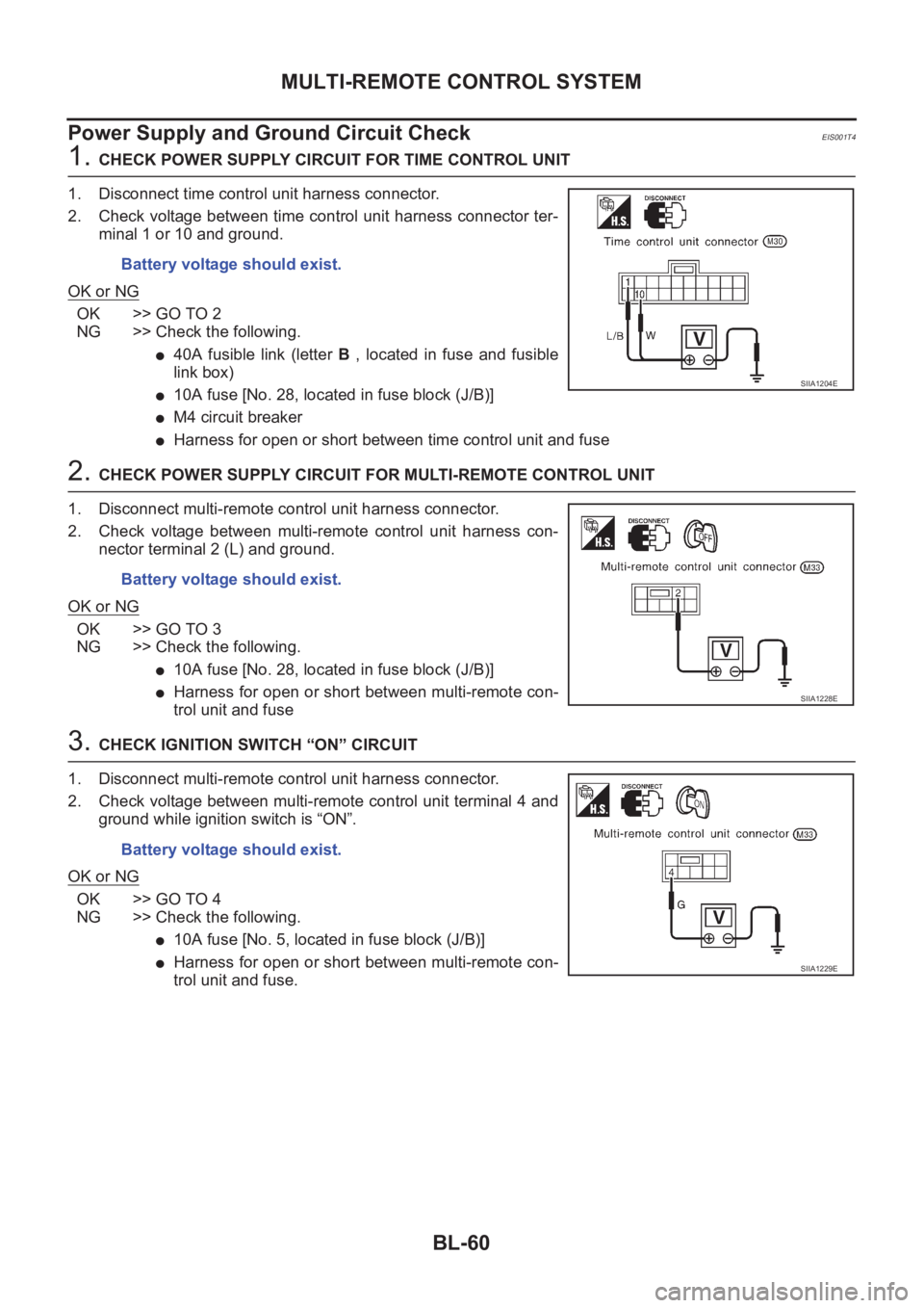
1. CHECK POWER SUPPLY CIRCUIT FOR TIME CONTROL UNIT
1. Disconnect time control unit harness connector.
2. Check voltage between time control unit harness connector ter-
minal 1 or 10 and ground.
OK or NG
OK >> GO TO 2
NG >> Check the following.
●40A fusible link (letter B , located in fuse and fusible
link box)
●10A fuse [No. 28, located in fuse block (J/B)]
●M4 circuit breaker
●Harness for open or short between time control unit and fuse
2. CHECK POWER SUPPLY CIRCUIT FOR MULTI-REMOTE CONTROL UNIT
1. Disconnect multi-remote control unit harness connector.
2. Check voltage between multi-remote control unit harness con-
nector terminal 2 (L) and ground.
OK or NG
OK >> GO TO 3
NG >> Check the following.
●10A fuse [No. 28, located in fuse block (J/B)]
●Harness for open or short between multi-remote con-
trol unit and fuse
3. CHECK IGNITION SWITCH “ON” CIRCUIT
1. Disconnect multi-remote control unit harness connector.
2. Check voltage between multi-remote control unit terminal 4 and
ground while ignition switch is “ON”.
OK or NG
OK >> GO TO 4
NG >> Check the following.
●10A fuse [No. 5, located in fuse block (J/B)]
●Harness for open or short between multi-remote con-
trol unit and fuse. Battery voltage should exist.
SIIA1204E
Battery voltage should exist.
SIIA1228E
Battery voltage should exist.
SIIA1229E
Page 3143 of 3833
NATS (NISSAN ANTI-THEFT SYSTEM)
BL-91
C
D
E
F
G
H
J
K
L
MA
B
BL
Diagnostic Procedure 1EIS001T7
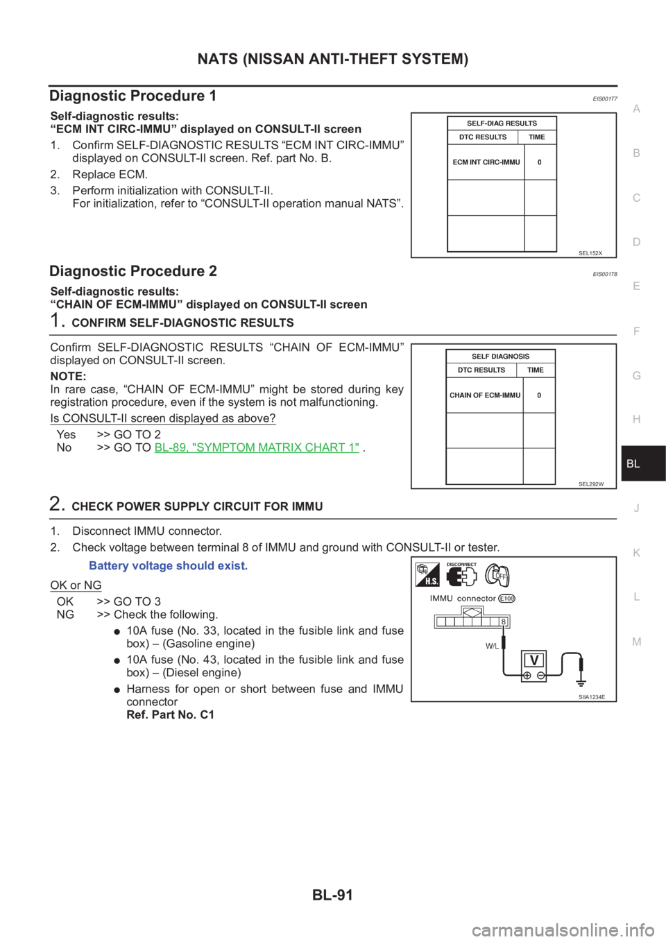
Self-diagnostic results:
“ECM INT CIRC-IMMU” displayed on CONSULT-II screen
1. Confirm SELF-DIAGNOSTIC RESULTS “ECM INT CIRC-IMMU”
displayed on CONSULT-II screen. Ref. part No. B.
2. Replace ECM.
3. Perform initialization with CONSULT-II.
For initialization, refer to “CONSULT-II operation manual NATS”.
Diagnostic Procedure 2EIS001T8
Self-diagnostic results:
“CHAIN OF ECM-IMMU” displayed on CONSULT-II screen
1.CONFIRM SELF-DIAGNOSTIC RESULTS
Confirm SELF-DIAGNOSTIC RESULTS “CHAIN OF ECM-IMMU”
displayed on CONSULT-II screen.
NOTE:
In rare case, “CHAIN OF ECM-IMMU” might be stored during key
registration procedure, even if the system is not malfunctioning.
Is CONSULT-II screen displayed as above?
Ye s > > G O T O 2
No >> GO TO BL-89, "
SYMPTOM MATRIX CHART 1" .
2.CHECK POWER SUPPLY CIRCUIT FOR IMMU
1. Disconnect IMMU connector.
2. Check voltage between terminal 8 of IMMU and ground with CONSULT-II or tester.
OK or NG
OK >> GO TO 3
NG >> Check the following.
●10A fuse (No. 33, located in the fusible link and fuse
box) – (Gasoline engine)
●10A fuse (No. 43, located in the fusible link and fuse
box) – (Diesel engine)
●Harness for open or short between fuse and IMMU
connector
Ref. Part No. C1
SEL152X
SEL292W
Battery voltage should exist.
SIIA1234E
Page 3162 of 3833
GW-10
REAR WINDOW DEFOGGER
REAR WINDOW DEFOGGER
PFP:25350
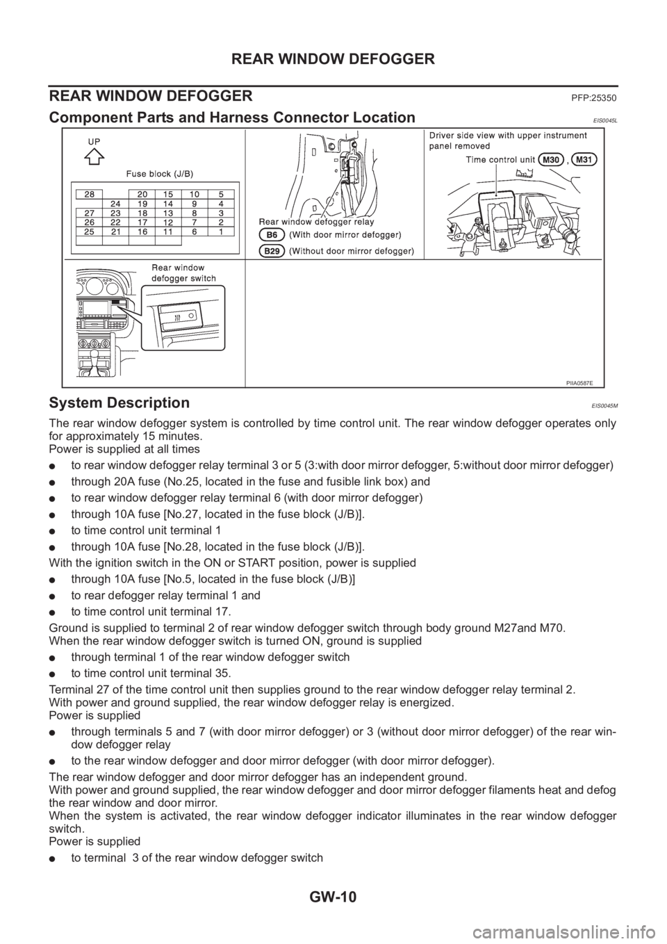
Component Parts and Harness Connector LocationEIS0045L
System DescriptionEIS0045M
The rear window defogger system is controlled by time control unit. The rear window defogger operates only
for approximately 15 minutes.
Power is supplied at all times
●to rear window defogger relay terminal 3 or 5 (3:with door mirror defogger, 5:without door mirror defogger)
●through 20A fuse (No.25, located in the fuse and fusible link box) and
●to rear window defogger relay terminal 6 (with door mirror defogger)
●through 10A fuse [No.27, located in the fuse block (J/B)].
●to time control unit terminal 1
●through 10A fuse [No.28, located in the fuse block (J/B)].
With the ignition switch in the ON or START position, power is supplied
●through 10A fuse [No.5, located in the fuse block (J/B)]
●to rear defogger relay terminal 1 and
●to time control unit terminal 17.
Ground is supplied to terminal 2 of rear window defogger switch through body ground M27and M70.
When the rear window defogger switch is turned ON, ground is supplied
●through terminal 1 of the rear window defogger switch
●to time control unit terminal 35.
Terminal 27 of the time control unit then supplies ground to the rear window defogger relay terminal 2.
With power and ground supplied, the rear window defogger relay is energized.
Power is supplied
●through terminals 5 and 7 (with door mirror defogger) or 3 (without door mirror defogger) of the rear win-
dow defogger relay
●to the rear window defogger and door mirror defogger (with door mirror defogger).
The rear window defogger and door mirror defogger has an independent ground.
With power and ground supplied, the rear window defogger and door mirror defogger filaments heat and defog
the rear window and door mirror.
When the system is activated, the rear window defogger indicator illuminates in the rear window defogger
switch.
Power is supplied
●to terminal 3 of the rear window defogger switch
PIIA0587E
Page 3175 of 3833

POWER WINDOW SYSTEM
GW-23
C
D
E
F
G
H
J
K
L
MA
B
GW
POWER WINDOW SYSTEMPFP:25401
Component Parts and Harness Connector LocationEIS0045V
System DescriptionEIS0045W
Power is supplied at all times
●from 40A fusible link (letter B , located in the fuse and fusible link box)
●through circuit breaker terminal 1
●through circuit breaker terminal 2
●to power window relay terminal 3 and
●to power window main switch terminal 5 (LHD models) or 3 (RHD models).
With ignition switch in ON or START position, power is supplied
●through 10A fuse [No. 5, located in the fuse block (J/B)]
●to power window relay terminal 1
Ground is supplied to power window relay terminal 2
●through body grounds M27 and M70.
When power and ground are supplied, the power window relay is energized and then power is supplied
●through power window relay terminal 5
●to power window main switch terminal 12,
●to passenger side power window switch terminal 5,
●to rear power window switch LH and RH terminals 5.
PIIA0588E
Page 3192 of 3833
GW-40
POWER WINDOW SYSTEM
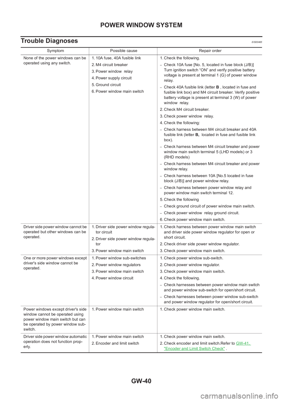
Trouble Diagnoses
EIS00465
Symptom Possible cause Repair order
None of the power windows can be
operated using any switch.1. 10A fuse, 40A fusible link
2. M4 circuit breaker
3. Power window relay
4. Power supply circuit
5. Ground circuit
6. Power window main switch1. Check the following.
–Check 10A fuse [No. 5, located in fuse block (J/B)]
Turn ignition switch “ON” and verify positive battery
voltage is present at terminal 1 (G) of power window
relay.
–Check 40A fusible link (letter B , located in fuse and
fusible link box) and M4 circuit breaker. Verify positive
battery voltage is present at terminal 3 (W) of power
window relay.
2. Check M4 circuit breaker.
3. Check power window relay.
4. Check the following:
–Check harness between M4 circuit breaker and 40A
fusible link (letter B, located in fuse and fusible link
box).
–Check harness between M4 circuit breaker and power
window main switch terminal 5 (LHD models) or 3
(RHD models)
–Check harness between M4 circuit breaker and power
window relay.
–Check harness between 10A [No.5 located in fuse
block (J/B)] and power window relay.
–Check harness between power window relay and
power window main switch terminal 12.
5. Check the following
–Check ground circuit of power window main switch.
–Check power window relay ground circuit.
6. Check power window main switch.
Driver side power window cannot be
operated but other windows can be
operated.1. Driver side power window regula-
tor circuit
2. Driver side power window regula-
tor
3. Power window main switch1. Check harness between power window main switch
and driver side power window regulator for open or
short circuit.
2. Check driver side power window regulator.
3. Check power window main switch.
One or more power windows except
driver's side window cannot be
operated.1. Power window sub-switches
2. Power window regulators
3. Power window main switch
4. Power window circuit1. Check power window sub-switch.
2. Check power window regulator.
3. Check power window main switch.
4. Check the following.
–Check harnesses between power window main switch
and power window sub-switch for open/short circuit.
–Check harnesses between power window sub-switch
and power window regulator for open/short circuit.
Power windows except driver's side
window cannot be operated using
power window main switch but can
be operated by power window sub-
switch.1. Power window main switch 1. Check power window main switch.
Driver side power window automatic
operation does not function prop-
erly.1. Power window main switch
2. Encoder and limit switch1. Check power window main switch.
2. Check encoder and limit switch.Refer to GW-41,
"Encoder and Limit Switch Check" .
Page 3448 of 3833
MTC-22
BLOWER FAN RESISTOR
BLOWER FAN RESISTOR
PFP:27150
Removal and InstallationEJS000XL
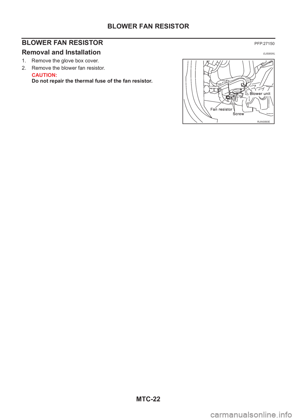
1. Remove the glove box cover.
2. Remove the blower fan resistor.
CAUTION:
Do not repair the thermal fuse of the fan resistor.
RJIA0093E
Page 3468 of 3833
SC-12
CHARGING SYSTEM
CHARGING SYSTEM
PFP:00011
System Description EKS00316
The alternator provides DC voltage to operate the vehicle's electrical system and to keep the battery charged.
The voltage output is controlled by the IC regulator.
Power is supplied at all times
●to alternator terminal 4 (S)
●through 10A fuse (No.34, located in the fuse and fusible link box)
●to alternator terminal B
●through 120A (Gasoline engine models) or 100A (Diesel engine models) fusible link (letter A, located in
the fuse and fusible link box).
Terminal B supplies power to charge the battery and operate the vehicle's electrical system. Output voltage is
controlled by the IC regulator at terminal 4 (S) detecting the input voltage. The charging circuit is protected by
the 120A (Gasoline engine models) or 100A (Diesel engine models) link.
The alternator is grounded to the engine block.
With the ignition switch in the ON or START position, power is supplied
●through 10A fuse [No. 11, located in the fuse block (J/B)]
●to combination meter terminal 46 (LHD models) or terminal 59 (RHD models) for the charge warning
lamp.
Ground is supplied with power and ground supplied
●to terminal 64 (LHD models) or terminal 54 ( RHD models) of the combination meter
●through terminal 3 (L) of the alternator
●to terminal E of the alternator
●through body ground E30.
The charge warning lamp will illuminate. When the alternator is providing sufficient voltage with the engine
running, the ground is opened and the charge warning lamp will go off.
If the charge warning lamp illuminates with the engine running, a malfunction is indicated.
Page 3476 of 3833
SC-20
STARTING SYSTEM
STARTING SYSTEM
PFP:00011
System Description EKS0031F
M/T MODELS
Power is supplied at all times
●through 30A fusible link (letter J, located in the fuse and fusible link box)
●to ignition switch terminal 1.
With the ignition switch in the START position, power is supplied
●from ignition switch terminal 5
●to starter motor harness connector terminal 1.
The starter motor plunger closes and provides a closed circuit between the battery and starter motor. The
starter motor is grounded to the engine block. With power and ground supplied, cranking occurs and the
engine starts.
A/T MODELS
Power is supplied at all times
●through 30A fusible link (letter J, located in the fuse and fusible link box)
●to ignition switch terminal 1.
With the ignition switch in the START position, power is supplied
●from ignition switch terminal 5
●to park/neutral position relay terminal 5.
With the ignition switch in the ON or START position, power is supplied
●through 10A fuse [No,13 located in the fuse block (J/B)]
●to park/neutral position relay terminal 1.
With the selector lever in the P or N position, ground is supplied
●to park/neutral position relay terminal 2
●through the park/neutral position switch terminals 1 and 2,and
●through body grounds F9 and F10.
Then park/neutral position relay is energized and power is supplied
●from park/neutral position relay terminal 3
●to starter motor harness connector terminal 1.
The starter motor plunger closes and provides a closed circuit between the battery and starter motor. The
starter motor is grounded to the engine block. With power and ground supplied, cranking occurs and the
engine starts.