2001 NISSAN X-TRAIL brake rotor
[x] Cancel search: brake rotorPage 2780 of 3833

PB-6
PARKING BRAKE SHOE
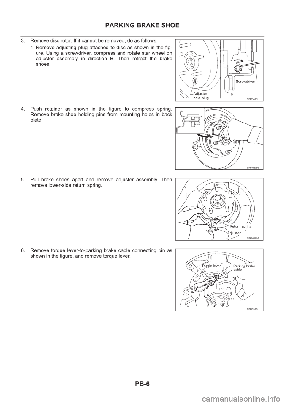
3. Remove disc rotor. If it cannot be removed, do as follows:
1. Remove adjusting plug attached to disc as shown in the fig-
ure. Using a screwdriver, compress and rotate star wheel on
adjuster assembly in direction B. Then retract the brake
shoes.
4. Push retainer as shown in the figure to compress spring.
Remove brake shoe holding pins from mounting holes in back
plate.
5. Pull brake shoes apart and remove adjuster assembly. Then
remove lower-side return spring.
6. Remove torque lever-to-parking brake cable connecting pin as
shown in the figure, and remove torque lever.
SBR046C
SFIA0279E
SFIA0280E
SBR095C
Page 2783 of 3833

PARKING BRAKE SHOE
PB-9
C
D
E
G
H
I
J
K
L
MA
B
PB
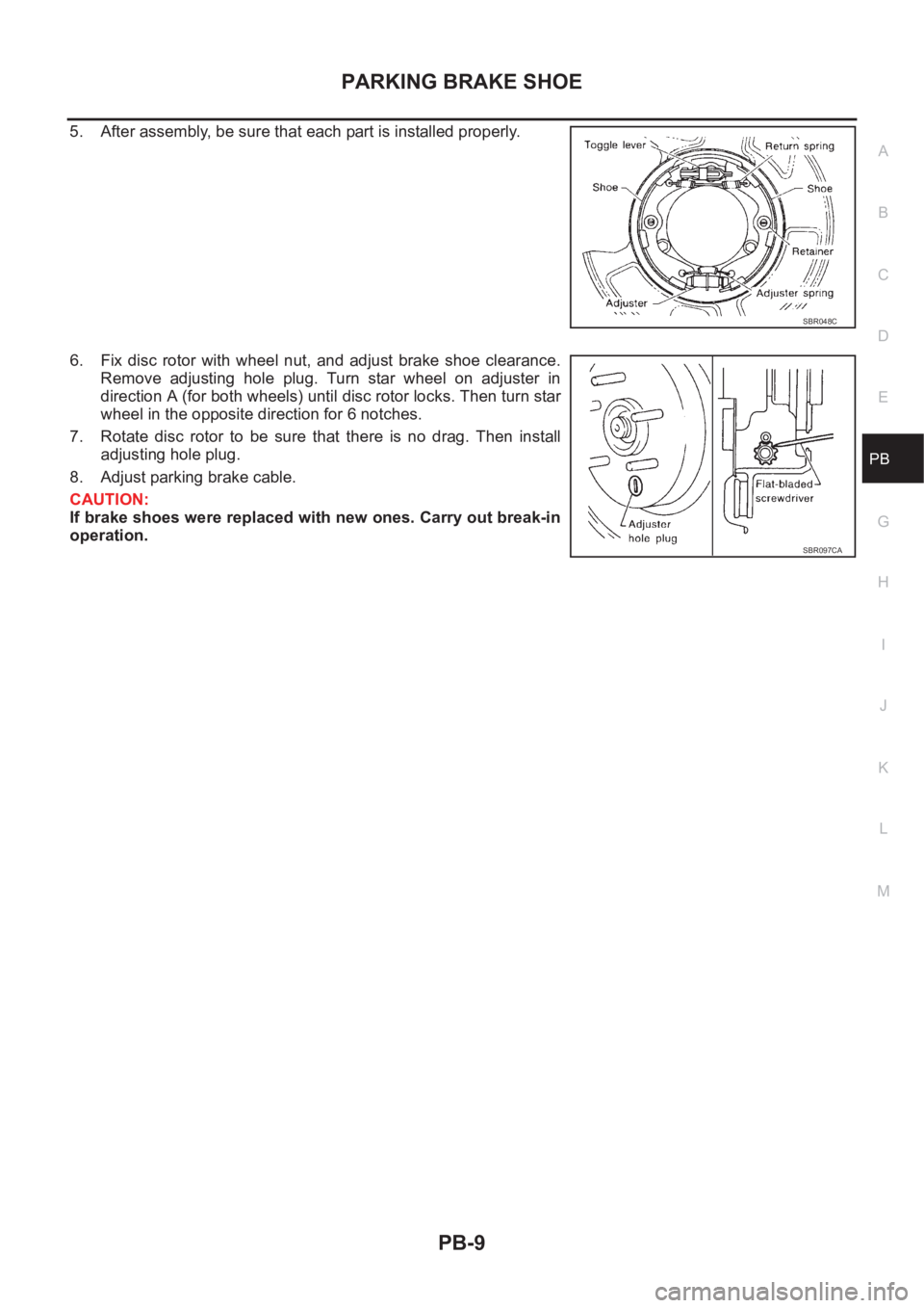
5. After assembly, be sure that each part is installed properly.
6. Fix disc rotor with wheel nut, and adjust brake shoe clearance.
Remove adjusting hole plug. Turn star wheel on adjuster in
direction A (for both wheels) until disc rotor locks. Then turn star
wheel in the opposite direction for 6 notches.
7. Rotate disc rotor to be sure that there is no drag. Then install
adjusting hole plug.
8. Adjust parking brake cable.
CAUTION:
If brake shoes were replaced with new ones. Carry out break-in
operation.
SBR048C
SBR097CA
Page 2786 of 3833

BRC-2
4WD ACTUATOR RELAY (4WD SOLENOID
A C T U AT O R R E L AY ) T U R N S O N / O F F F R E -
QUENTLY ............................................................ 42
ABS Warning Lamp Does Not Illuminate. (ABS
Warning Lamp Does Not Come On When The Igni-
tion Switch Is Turned ON.) ...................................... 42
ABS Warning Lamp Illuminates With Ignition ON,
But Does Not Illuminates After A Few Seconds.
(ABS Warning Lamp Has Illuminated.) ................... 42
4WD Warning Lamp Does Not Illuminate With Igni-
tion ON. .................................................................. 43
4WD Warning Lamp Does Not Go Out Several Sec-
onds After Engine Is Started. (Drive Mode Indicator
Lamp Goes Out.) .................................................... 43
Heavy Tight-corner Braking Symptom Occurs
When The Vehicle Is Driven In Auto Mode And The
Steering Wheel Is Turned Fully To Either Side After
The Engine Is Started. ............................................ 44
Drive Modes Cannot Be Switched After Engine Is
Started. ................................................................... 45
Wheel Driving, 4WD Warning Lamp Flashes Rap-
idly. (When It Flashes For Approx. One Minute, Then
Does Not Illuminate.) .............................................. 45
Wheel Driving, 4WD Warning Lamp Flashes Slowly.
(When It Continues To Illuminate Until Engine Turns
OFF.) ....................................................................... 45
Vehicle Does Not Enter 4WD Mode Even Though
4WD Warning Lamp Is OFF. ................................... 46
Tight-corner Braking Symptom Occurs When The
Vehicle Is Started In Auto Mode (4WD Warning
Lamp Remain OFF). ............................................... 46
E-TS Actuator Relay (4WD Solenoid Actuator
Relay) Turns ON/OFF Frequently. .......................... 46
Inspection Of Drive Mode Change-over Switch Path ... 47
4WD/ABS CONTROL UNIT ...................................... 48
Removal and Installation ........................................ 48
REMOVAL ........................................................... 48
INSTALLATION .................................................... 48
WHEEL SENSORS ................................................... 49
Removal and Installation ........................................ 49
G-SENSOR (4WD MODEL ONLY) ............................ 50
Removal and Installation ........................................ 50
SENSOR ROTOR ................................................... ... 51
Removal and Installation ........................................ 51
REMOVAL ........................................................... 51
INSTALLATION .................................................... 51
ACTUATOR ............................................................... 52
Removal and Installation ........................................ 52
REMOVAL ........................................................... 53
INSTALLATION .................................................... 53
ESP/TCS/ABS
PRECAUTIONS ......................................................... 54
Precautions for Brake System ................................ 54
Precautions for Brake Control ................................ 54
Precautions for CAN System .................................. 54
FOR INSPECTION .............................................. 54
FOR HARNESS REPAIR .................................... 55PREPARATION ......................................................... 56
Special Service Tool ................................................ 56
Commercial Service Tool ........................................ 56
ON-VEHICLE SERVICE ............................................ 57
Adjustment of Neutral Position of Steering Wheel
Angle Sensor .......................................................... 57
GENERAL INFORMATION ....................................... 59
Fail-Safe .................................................................. 59
ABS SYSTEM ...................................................... 59
ESP/TCS SYSTEM .............................................. 59
Hydraulic Circuit ...................................................... 59
ABS Functions ........................................................ 59
TCS Functions ........................................................ 60
ESP Functions ........................................................ 60
System Diagram ..................................................... 61
CAN COMMUNICATION ........................................... 62
System Description ................................................. 62
FOR A/T MODELS ............................................... 62
FOR M/T MODELS .............................................. 62
TROUBLE DIAGNOSIS ............................................ 64
How to Perform Trouble Diagnoses for Quick and
Accurate Repair ...................................................... 64
INTRODUCTION ................................................. 64
WORK FLOW ...................................................... 65
ASKING COMPLAINTS ....................................... 66
EXAMPLE OF DIAGNOSIS SHEET .................... 66
Component Parts and Harness Connector Location ... 67
Schematic ............................................................... 68
Wiring Diagram —ESP/TCS/ABS— ..................... 69
Control Unit Input/Output Signal Standard .............. 75
STANDARDS USING A CIRCUIT TESTER AND
OSCILLOSCOPE ................................................. 75
STANDARDS WITH CONSULT-II ........................ 78
Functions of CONSULT-II ....................................... 80
CONSULT-II MAINLY FUNCTION APPLICA-
TION TO ESP/TCS/ABS ...................................... 80
SELF-DIAGNOSIS ............................................... 81
DATA MONITOR .................................................. 83
ACTIVE TEST ...................................................... 87
For Correct and Quick Diagnosis ............................ 90
PRECAUTIONS FOR TROUBLE DIAGNOSIS ... 90
Basic Inspection ...................................................... 91
PRELIMINARY CHECK 1: (BRAKE FLUID
LEVEL AND LEAK INSPECTION) ....................... 91
PRELIMINARY CHECK 2: (INSPECTION FOR
LOOSE POWER SUPPLY TERMINAL) ............... 92
PRELIMINARY CHECK 3: (INSPECTION FOR
ABS WARNING LAMP, ESP OFF INDICATOR
LAMP, AND SLIP INDICATOR LAMP) ................. 92
Inspection 1 Wheel Sensor and Circuit ................... 92
Inspection 2 Engine System ................................... 94
Inspection 3 ESP/TCS/ABS Control Unit System ... 94
Inspection 4 Pressure Sensor and the Circuit
between Pressure Sensor and ESP/TCS/ABS Con-
trol Unit. ................................................................... 95
Inspection 5 Steering wheel Angle Sensor and the
Circuit between Steering Wheel Angle Sensor and
ESP/TCS/ABS Control Unit. ................................... 96
Inspection 6 Yaw Rate Sensor and Side G sensor
Page 2787 of 3833

BRC-3
C
D
E
G
H
I
J
K
L
MA
B
BRC and the Circuit between Yaw Rate Sensor and Side
G sensor and ESP/TCS/ABS Control Unit. ............ 98
Inspection 7 Solenoid Valve, ESP Switch-over Sole-
noid Valve and Circuit ......................................... ... 99
Inspection 8 Actuator Motor, Motor Relay and Circuit
. 102
Inspection 9 Actuator Relay and Circuit ............... 104
Inspection 10 Stop Lamp Switch and Circuit ........ 106
Inspection 11 ESP/TCS/ABS Control Unit Power
Supply Circuit ....................................................... 106
Inspection 12 When “EMERGENCY BRAKE” is
indicated in the Self-Diagnosis Results ................ 108
Inspection 13 When “ST ANG SEN SIGNAL” is Indi-
cated in the Self-Diagnosis Results .....................108
Inspection 14 Brake Fluid Level of Reservoir Tank,
Communication Circuit between ESP/TCS/ABS
Control Unit and Brake Fluid Level Warning Switch . 109
Inspection 15 CAN Communication Circuit, ESP/
TCS/ABS Control Unit and Steering Wheel Angle
Sensor ................................................................... 110
Component Check ............................................... . 111
ESP OFF SWITCH ............................................ . 111
ESP RELAY BOX .............................................. . 111
ESP ACTUATOR ............................................... 112
Symptom 1: ABS Works Frequently. ..................... 114
Symptom 2: Unexpected Pedal Action .................. 114
Symptom 3: Longer Stopping Distance ................. 115
Symptom 4: ABS Does Not Work. ........................ 116Symptom 5: Pedal Vibration and Noise ................116
Symptom 6: ESP OFF Indicator Lamp Does Not Illu-
minate ...................................................................117
Symptom 7: SLIP Indicator Lamp Does Not Illumi-
nate .......................................................................118
Symptom 8: During ESP/TCS/ABS Control, Vehicle
Behavior is Jerky. .................................................118
ESP/TCS/ABS CONTROL UNIT ............................120
Removal and Installation ......................................120
REMOVAL .........................................................120
INSTALLATION .................................................120
WHEEL SPEED SENSORS ....................................121
Removal and Installation ......................................121
SENSOR ROTOR ...................................................122
Removal and Installation ......................................122
REMOVAL .........................................................122
INSTALLATION .................................................122
ESP/TCS/ABS ACTUATOR AND RELAY BOX .....123
Removal and Installation ......................................123
YAW RATE/SIDE G SENSOR .................................124
Removal and Installation ......................................124
REMOVAL .........................................................124
INSTALLATION .................................................124
ESP OFF SWITCH ................................................. .125
Removal and Installation ......................................125
REMOVAL .........................................................125
INSTALLATION .................................................125
Page 2788 of 3833
![NISSAN X-TRAIL 2001 Service Repair Manual BRC-4
[4WD/ABS]
PRECAUTIONS
[4WD/ABS]PRECAUTIONSPFP:00001
Precautions for brake systemEFS001B6
●Recommended fluid is brake fluid “DOT 3 ”or “DOT 4”.
●Never reuse drained brake fluid.
●Be NISSAN X-TRAIL 2001 Service Repair Manual BRC-4
[4WD/ABS]
PRECAUTIONS
[4WD/ABS]PRECAUTIONSPFP:00001
Precautions for brake systemEFS001B6
●Recommended fluid is brake fluid “DOT 3 ”or “DOT 4”.
●Never reuse drained brake fluid.
●Be](/manual-img/5/57405/w960_57405-2787.png)
BRC-4
[4WD/ABS]
PRECAUTIONS
[4WD/ABS]PRECAUTIONSPFP:00001
Precautions for brake systemEFS001B6
●Recommended fluid is brake fluid “DOT 3 ”or “DOT 4”.
●Never reuse drained brake fluid.
●Be careful not to splash brake fluid on painted areas.
●To clean or wash all parts of master cylinder, disc brake caliper and wheel cylinder, use clean brake fluid.
●Never use mineral oils such as gasoline or kerosene. They will ruin rubber parts of the hydraulic system.
●Use flare nut wrench when removing and installing brake tube.
●Always torque brake lines when installing.
●Burnish the brake contact surfaces after refinishing or replacing
drums or rotors, after replacing pads or linings, or if a soft pedal
occurs at very low mileage. Refer to BR-10, "
Brake Burnishing
Procedure" .
●Before working, turn OFF ignition switch. Disconnect connectors
for ABS actuator and control module or battery terminals.
WARNING:
●Clean brake pads and shoes with a waste cloth, then wipe
with a dust collector.
Precautions for brake controlEFS001B7
●If malfunction is indicated by 4WD warning lamp and/or ABS warning lamp, collect necessary information
from customer (what symptoms are present under what conditions). Find out possible causes before start-
ing service. Besides electrical system inspection, check operation of ABS actuator.
●If malfunction is detected, proceed to trouble diagnosis after checking tire pressure and tire wear.
●Stopping distance or steering stability may be deteriorated by the following conditions. Tire size and type
are in improper combination. Brake pads are not Nissan genuine parts.
●Fitting tires of different size on vehicle can be cause of longitudinal vibration. Always use tires of the same
size and brand. Exchange front and rear tires on the following conditions: Longitudinal vibration occurs in
vehicle with tires of the same size and brand. After replacement, perform trouble diagnosis. 1580|None
●4WD/ABS function may have a failure or error under following condition: There is radio, antenna, or
antenna lead-in wire (including wiring) near control module.
●If aftermarket parts (e.g. Car stereo equipment, CD player) have been installed, check electrical har-
nesses for pinches, open, and improper wiring.
SBR820BA
Page 2838 of 3833
![NISSAN X-TRAIL 2001 Service Repair Manual BRC-54
[ESP/TCS/ABS]
PRECAUTIONS
[ESP/TCS/ABS]PRECAUTIONSPFP:00001
Precautions for Brake SystemEFS0019O
●Recommended fluid is brake fluid “DOT 3” or “DOT 4”.
●Never reuse drained brake flu NISSAN X-TRAIL 2001 Service Repair Manual BRC-54
[ESP/TCS/ABS]
PRECAUTIONS
[ESP/TCS/ABS]PRECAUTIONSPFP:00001
Precautions for Brake SystemEFS0019O
●Recommended fluid is brake fluid “DOT 3” or “DOT 4”.
●Never reuse drained brake flu](/manual-img/5/57405/w960_57405-2837.png)
BRC-54
[ESP/TCS/ABS]
PRECAUTIONS
[ESP/TCS/ABS]PRECAUTIONSPFP:00001
Precautions for Brake SystemEFS0019O
●Recommended fluid is brake fluid “DOT 3” or “DOT 4”.
●Never reuse drained brake fluid.
●Be careful not to splash brake fluid on painted areas; it may cause paint damage. If brake fluid is splashed
on painted areas, wash it away with water immediately.
●Never use mineral oils such as gasoline or kerosene. They will ruin rubber parts of hydraulic system.
●Use flare nut wrench when removing and installing brake tubes.
●Always torque brake lines when installing.
●Before working, turn the ignition switch OFF and disconnect the
connectors for the ESP/TCS/ABS actuator and control unit or
the battery terminals.
●Burnish the brake contact surfaces after refinishing or replacing
drums or rotors, after replacing pads or linings, or if a soft pedal
occurs at very low mileage. Refer to BR-10, "
Brake Burnishing
Procedure" .
WARNING:
Clean brakes with a vacuum dust collector to minimize risk
of health hazard from powder caused by friction.
Precautions for Brake ControlEFS0019P
●During the ESP/TCS/ABS operation, the brake pedal vibrates lightly and its mechanical noise may be
heard. This is a normal condition.
●Just after starting the vehicle after ignition switch ON, the brake pedal may vibrate or the motor operating
noise may be heard from the engine compartment. This is a normal status of the operation check.
●The stopping distance may be longer than that of vehicles without ABS when the vehicle drives on rough,
gravel, or snowy (fresh deep snow) road.
●If a malfunction is indicated by the ABS warning lamp, or other warning lamps, collect the necessary infor-
mation from the customer (what symptoms are present under what conditions) and find out the possible
causes before starting the service. Besides the electrical system inspection, check the booster operation,
brake fluid level, and oil leaks.
●If the tire size and type are used in a improper combination, or the brake pads are not NISSAN genuine
parts, the stopping distance or steering stability may deteriorate.
●If there is a radio, antenna, or antenna lead-in wire (including wiring) near the control unit, the ESP/TCS/
ABS function may have a malfunction or error.
●If aftermarket parts (e.g. Car stereo equipment, CD player) have been installed, check the electrical har-
nesses for pinches, open, and improper wiring.
Precautions for CAN SystemEFS001CP
FOR INSPECTION
●Do not apply voltage of 7.0V or higher to the measurement terminals.
●Use the tester with its open terminal voltage being 7.0V or less.
●Before harness inspection, turn the ignition switch off, disconnect the negative battery terminal.
SBR820BA
Page 2876 of 3833
![NISSAN X-TRAIL 2001 Service Repair Manual BRC-92
[ESP/TCS/ABS]
TROUBLE DIAGNOSIS
●If a leak or oozing is detected on the ESP actuator body, wipe the applicable part with a clean cloth.
Then check again for leaks, and if th NISSAN X-TRAIL 2001 Service Repair Manual BRC-92
[ESP/TCS/ABS]
TROUBLE DIAGNOSIS
●If a leak or oozing is detected on the ESP actuator body, wipe the applicable part with a clean cloth.
Then check again for leaks, and if th](/manual-img/5/57405/w960_57405-2875.png)
BRC-92
[ESP/TCS/ABS]
TROUBLE DIAGNOSIS
●If a leak or oozing is detected on the ESP actuator body, wipe the applicable part with a clean cloth.
Then check again for leaks, and if there is still a leak or oozing, replace the ESP actuator body.
CAUTION:
Do not disassemble the actuator body.
3. Check the brake disc rotor and pads.
PRELIMINARY CHECK 2: (INSPECTION FOR LOOSE POWER SUPPLY TERMINAL)
Check the battery for looseness on the battery positive/negative terminals and ground connection. If loose-
ness is detected, tighten the piping to the specified torque. Check that the battery voltage does not drop and
the alternator is normal.
PRELIMINARY CHECK 3: (INSPECTION FOR ABS WARNING LAMP, ESP OFF INDICATOR
LAMP, AND SLIP INDICATOR LAMP)
1. Check that the ABS warning lamp is ON for Approx. 0.5 seconds when the ignition switch is turned ON. If
it does not turn on, check the ABS warning lamp and the circuit, and the combination meter.
2. Check that ESP OFF indicator lamp is ON for Approx. 0.5 seconds when the ignition switch is turned ON.
If it does not turn ON, check the ESP OFF indicator lamp and the circuit, and the combination meter.
3. Check that the SLIP indicator lamp is ON for Approx. 0.5 seconds when the ignition switch is turned ON. If
it does not turn ON, check the SLIP indicator lamp and the circuit.
4. With the engine running, check the ESP OFF indicator lamp turns ON and OFF when the ESP OFF
switch turns ON and OFF. If it dose not operate in accordance with the switch, check the ESP OFF switch
and the circuit.
5. Check that the ESP OFF indicator lamp turns OFF after Approx. 2 seconds delay when the ESP OFF
switch turned ON (The ESP/TCS system was not operated). If the ESP OFF indicator lamp does not turn
OFF in 10 seconds from the engine start, perform the self-diagnosis of ESP/TCS/ABS control unit.
Inspection 1 Wheel Sensor and CircuitEFS001AB
Inspection procedure
1. SELF-DIAGNOSIS RESULT CHECK 1
Check the self-diagnosis results.
Are any self-diagnosis result items above indicated?
>> GO TO 2.
2. CHECK THE CONNECTOR
Remove connectors of the wheel sensor which is malfunctioning and the ESP/TCS/ABS control unit. Check
whether the deformation of terminal, or incorporate connection of connectors. Then, connect connectors. In
addition, check if the wheel sensor cable is damaged due to friction.
Does ABS warning lamp is out when driving 30 km/h (19 MPH) for Approx. One minute?
YES >> Check is completed.
NO >> GO TO 3.
Self-diagnosis results
CONSULT-II indication item
ABS SENSOR [ABNORMAL SIGNAL]
FR RH SENSOR – 1
FR RH SENSOR – 2
FR LH SENSOR – 1
FR LH SENSOR – 2
RR RH SENSOR – 1
RR RH SENSOR – 2
RR LH SENSOR – 1
RR LH SENSOR – 2
Page 2898 of 3833
![NISSAN X-TRAIL 2001 Service Repair Manual BRC-114
[ESP/TCS/ABS]
TROUBLE DIAGNOSIS
Actuator operation check
1. Connect 9 and 10 terminals of actuator to 40 and 41 terminals of
relay box.
2. Measure the motor voltage (No.4 terminal to bo NISSAN X-TRAIL 2001 Service Repair Manual BRC-114
[ESP/TCS/ABS]
TROUBLE DIAGNOSIS
Actuator operation check
1. Connect 9 and 10 terminals of actuator to 40 and 41 terminals of
relay box.
2. Measure the motor voltage (No.4 terminal to bo](/manual-img/5/57405/w960_57405-2897.png)
BRC-114
[ESP/TCS/ABS]
TROUBLE DIAGNOSIS
Actuator operation check
1. Connect 9 and 10 terminals of actuator to 40 and 41 terminals of
relay box.
2. Measure the motor voltage (No.4 terminal to body earth) with
oscilloscope. Then check the motor reverse voltage occasioned
time.
The motor reverse voltage occasioned time is more than 0.1
sec.
CAUTION:
●Perform checking of motor relay unit. Then confirm that
relay functions.
●Driving actuator motor is with in 4 sec. to prevent heating
up.
●Standard condition of the motor reverse voltage occa-
sioned time is: Battery voltage is 12V. Temperature 20°.
when the battery voltage or temperature is lower than the
standard, the motor reverse voltage occasioned time
becomes slightly shorter.
Symptom 1: ABS Works Frequently.EFS001AS
Inspection procedure
1. INSPECTION START
Check the wheel sensor system.
●Sensor mounting inspection
●Sensor pick-up inspection for iron chips
●Sensor rotor inspection (e.g. Number of teeth, damaged teeth)
●Sensor connector engagement inspection
Is inspection result OK?
YES >> GO TO 2.
NO >> Refer to wheel sensor and rotor lines.
2. LOOSENESS INSPECTION
Check the front axle for looseness.
Is inspection result OK?
YES >>BRC-114, "Symptom 2: Unexpected Pedal Action"
NO >> Axle inspection and repair
Symptom 2: Unexpected Pedal ActionEFS001AT
Inspection procedure
1. BRAKE PEDAL STROKE INSPECTION
Check the brake pedal stroke.
Is stroke excessively long?
YES >> Check the bleeding and brake system.
NO >> GO TO 2.
SFIA0910E