Page 3362 of 3833
ATC-86
TROUBLE DIAGNOSIS
Insufficient Cooling
EJS002FS
SYMPTOM: Insufficient cooling
INSPECTION FLOW
*1ATC-47, "PROCEDURE", see No. 1. *2ATC-64, "Air Mix Door Motor Circuit".*3AT C - 9 0 , "Test Reading (QR
Engine)",AT C - 9 0 , "Test Reading
(YD Engine)" .
*4ATC-52, "
AUXILIARY MECHA-
NISM: TEMPERATURE SETTING
TRIMMER"
*5ATC-59, "LAN System Circuit".*6AT C - 7 0 , "Blower Motor Circuit".
RJIA1948E
Page 3363 of 3833
TROUBLE DIAGNOSIS
ATC-87
C
D
E
F
G
H
I
K
L
MA
B
AT C
*7ATC-78, "Magnet Clutch Circuit".*8AT C - 8 8 , "PERFORMANCE TEST
DIAGNOSES"
*9ATC-54, "Operational Check".
*10ATC-47, "
PROCEDURE", see No.5
to 7.*11 QR engine; EM-12, "Checking Drive
Belts" .
YD engine; EM-118, "
Checking Drive
Belts" .*12 QR25 engine; (WITH EURO-OBD)
EC-323, "
COOLING FAN CON-
TROL" .
QR25 engine; (WITHOOUT EUR-
OBD)EC-603, "
COOLING FAN
CONTROL" .
QR20 engine; (WITH EURO-OBD)
EC-1050, "
COOLING FAN CON-
TROL" .
QR20 engine; (WITHOUT EURO-
OBD)EC-1287, "
COOLING FAN
CONTROL" .
YD engine; EC-1508, "
SYSTEM
DESCRIPTION" .
Page 3368 of 3833

ATC-92
TROUBLE DIAGNOSIS
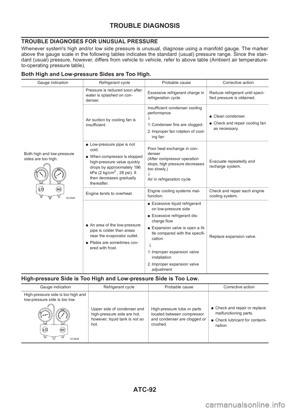
TROUBLE DIAGNOSES FOR UNUSUAL PRESSURE
Whenever system's high and/or low side pressure is unusual, diagnose using a manifold gauge. The marker
above the gauge scale in the following tables indicates the standard (usual) pressure range. Since the stan-
dard (usual) pressure, however, differs from vehicle to vehicle, refer to above table (Ambient air temperature-
to-operating pressure table).
Both High and Low-pressure Sides are Too High.
High-pressure Side is Too High and Low-pressure Side is Too Low.
Gauge indication Refrigerant cycle Probable cause Corrective action
Both high and low-pressure
sides are too high.Pressure is reduced soon after
water is splashed on con-
denser.Excessive refrigerant charge in
refrigeration cycleReduce refrigerant until speci-
fied pressure is obtained.
Air suction by cooling fan is
insufficient.Insufficient condenser cooling
performance
↓
1. Condenser fins are clogged.
2. Improper fan rotation of cool-
ing fan
●Clean condenser.
●Check and repair cooling fan
as necessary.
●Low-pressure pipe is not
cold.
●When compressor is stopped
high-pressure value quickly
drops by approximately 196
kPa (2 kg/cm
2 , 28 psi). It
then decreases gradually
thereafter.Poor heat exchange in con-
denser
(After compressor operation
stops, high pressure decreases
too slowly.)
↓
Air in refrigeration cycleEvacuate repeatedly and
recharge system.
Engine tends to overheat.Engine cooling systems mal-
function.Check and repair each engine
cooling system.
●An area of the low-pressure
pipe is colder than areas
near the evaporator outlet.
●Plates are sometimes cov-
ered with frost.
●Excessive liquid refrigerant
on low-pressure side
●Excessive refrigerant dis-
charge flow
●Expansion valve is open a lit-
tle compared with the specifi-
cation.
↓
1. Improper expansion valve
installation
2. Improper expansion valve
adjustmentReplace expansion valve.
AC359A
Gauge indication Refrigerant cycle Probable cause Corrective action
High-pressure side is too high and
low-pressure side is too low.
Upper side of condenser and
high-pressure side are hot,
however, liquid tank is not so
hot.High-pressure tube or parts
located between compressor
and condenser are clogged or
crushed.
●Check and repair or replace
malfunctioning parts.
●Check lubricant for contami-
nation.
AC360A
Page 3370 of 3833

ATC-94
TROUBLE DIAGNOSIS
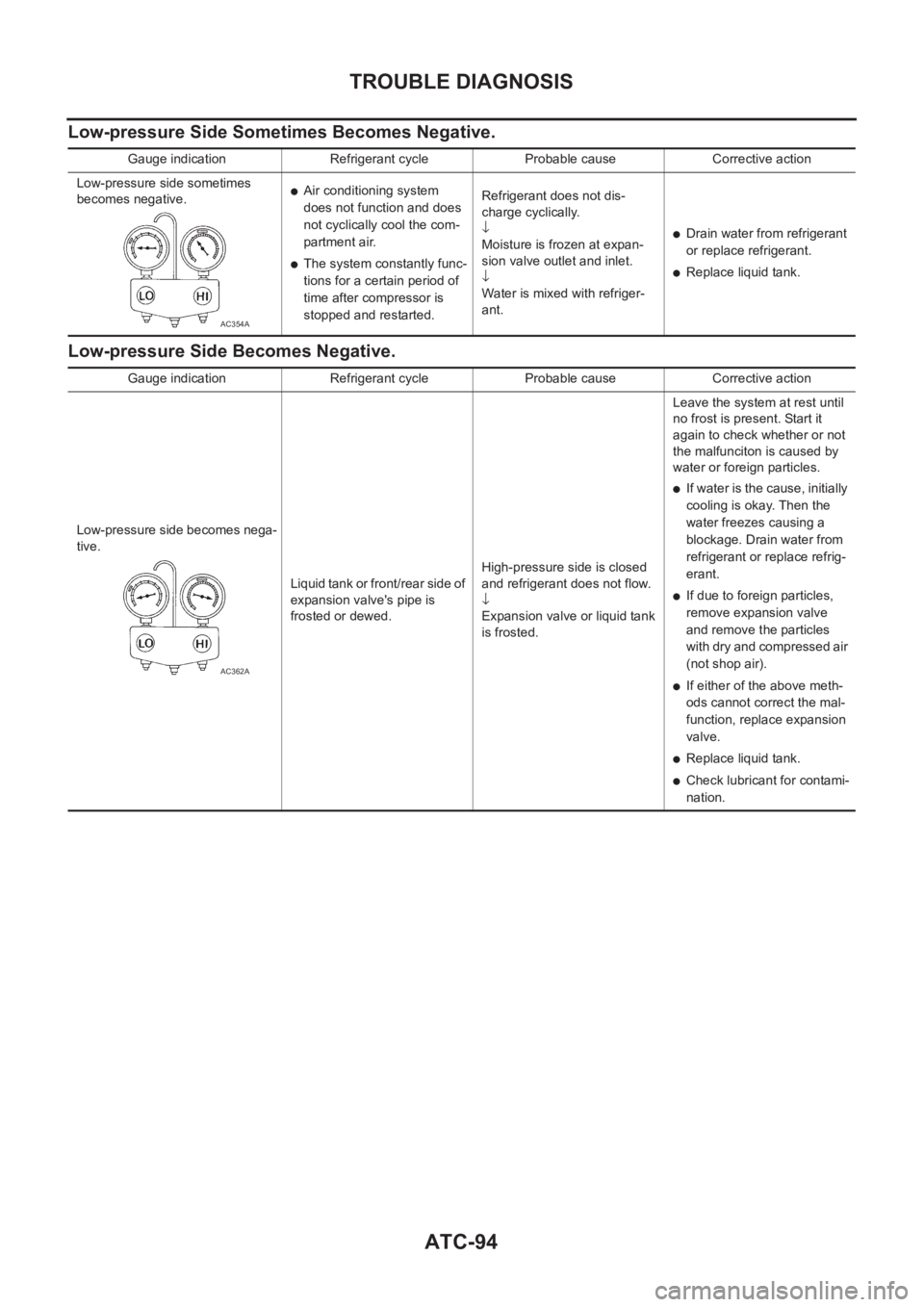
Low-pressure Side Sometimes Becomes Negative.
Low-pressure Side Becomes Negative.
Gauge indication Refrigerant cycle Probable cause Corrective action
Low-pressure side sometimes
becomes negative.
●Air conditioning system
does not function and does
not cyclically cool the com-
partment air.
●The system constantly func-
tions for a certain period of
time after compressor is
stopped and restarted.Refrigerant does not dis-
charge cyclically.
↓
Moisture is frozen at expan-
sion valve outlet and inlet.
↓
Water is mixed with refriger-
ant.
●Drain water from refrigerant
or replace refrigerant.
●Replace liquid tank.
AC354A
Gauge indication Refrigerant cycle Probable cause Corrective action
Low-pressure side becomes nega-
tive.
Liquid tank or front/rear side of
expansion valve's pipe is
frosted or dewed.High-pressure side is closed
and refrigerant does not flow.
↓
Expansion valve or liquid tank
is frosted.Leave the system at rest until
no frost is present. Start it
again to check whether or not
the malfunciton is caused by
water or foreign particles.
●If water is the cause, initially
cooling is okay. Then the
water freezes causing a
blockage. Drain water from
refrigerant or replace refrig-
erant.
●If due to foreign particles,
remove expansion valve
and remove the particles
with dry and compressed air
(not shop air).
●If either of the above meth-
ods cannot correct the mal-
function, replace expansion
valve.
●Replace liquid tank.
●Check lubricant for contami-
nation.
AC362A
Page 3378 of 3833
ATC-102
TROUBLE DIAGNOSIS
COMPONENT INSPECTION
Ambient Sensor
After disconnecting ambient sensor harness connector, measure
resistance between terminals 2 and 1 at sensor harness side, using
the table below.
If NG, replace ambient sensor.
In-vehicle Sensor CircuitEJS001HC
COMPONENT DESCRIPTION
In-vehicle sensor
The in-vehicle sensor is located on instrument lower panel. It con-
verts variations in temperature of compartment air drawn from the
aspirator into a resistance value. It is then input into the auto ampli-
fier.
Aspirator
The aspirator is located on front side of heater & cooling unit. It pro-
duces vacuum pressure due to air discharged from the heater &
cooling unit, continuously taking compartment air in the aspirator.
Temperature °C (°F) Resistance kΩ
-15 (5) 12.73
-10 (14) 9.92
-5 (23) 7.80
0 (32) 6.19
5 (41) 4.95
10 (50) 3.99
15 (59) 3.24
20 (68) 2.65
25 (77) 2.19
30 (86) 1.81
35 (95) 1.51
40 (104) 1.27
45 (113) 1.07
RJIA0556E
RJIA0049E
RJIA0557E
Page 3384 of 3833
ATC-108
TROUBLE DIAGNOSIS
Intake Sensor Circuit
EJS001HE
COMPONENT DESCRIPTION
Intake Sensor
The intake sensor is located on the heater & cooling unit. It converts
temperature of air after it passes through the evaporator into a resis-
tance value which is then input to the auto amp.
After disconnecting intake sensor harness connector, measure resis-
tance between terminals 1 and 2 at sensor harness side, using the
table below.
If NG, replace intake sensor.
DIAGNOSTIC PROCEDURE
SYMPTOM: Intake sensor circuit is open or shorted. (24 or -24) is
indicated on auto amp. as a result of conducting Self-diagnosis
STEP 2.)
Temperature °C (°F)Resistance kΩ
With gasoline engine With diesel engine
-15 (5) 12.34 18.63
-10 (14) 9.62 14.15
-5 (23) 7.56 10.86
0 (32) 6.00 8.41
5 (41) 4.80 6.58
10 (50) 3.87 5.19
15 (59) 3.15 4.12
20 (68) 2.57 3.30
25 (77) 2.12 2.67
30 (86) 1.76 2.17
35 (95) 1.47 1.78
40 (104) 1.23 1.46
45 (113) 1.04 1.21
RJIA0051E
RJIA0567E
Page 3393 of 3833
BLOWER UNIT
ATC-117
C
D
E
F
G
H
I
K
L
MA
B
AT C
Disassembly and AssemblyEJS000UM
NOTE:
This illustration is for RHD models. The layout for LHD models is symmetrically opposite.
CAUTION:
If retaining tabs are damaged while disassembling blower unit,
use 9 screws (27111-2Y000) to assemble blower unit.
1. Fan control amplifier 2. Screw 3. Cooling hose
4. Blower fan motor assembly 5. Washer 6. Blower fan
7. Nut 8. Screw 9. Bell mouth
10. Intake door lever 2 11. Intake door lever 1 12. Intake door link
13. Intake door motor 14. Screw 15. Upper case 2
16. Intake door 2 17. Intake door 1 18. Upper case 1
19. Screw 20. Ventilation air filter 21. Filter cover
RJIA0053J
RJIA0097E
Page 3394 of 3833
ATC-118
BLOWER MOTOR
BLOWER MOTOR
PFP:27226
Removal and InstallationEJS000UN
1. Remove the blower unit. Refer to AT C - 11 6 , "Removal and Instal-
lation"
2. Separate the blower unit.
3. Remove the cooling hose, fan control amp. and blower fan.
RJIA0054E
RJIA0055E