Page 3284 of 3833
ATC-8
PRECAUTIONS
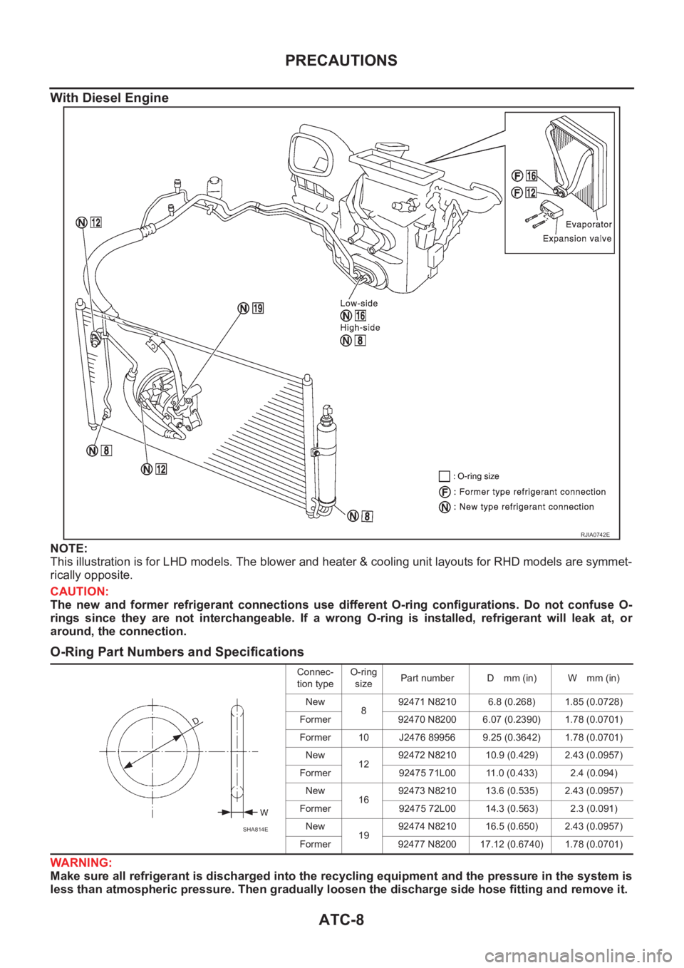
With Diesel Engine
NOTE:
This illustration is for LHD models. The blower and heater & cooling unit layouts for RHD models are symmet-
rically opposite.
CAUTION:
The new and former refrigerant connections use different O-ring configurations. Do not confuse O-
rings since they are not interchangeable. If a wrong O-ring is installed, refrigerant will leak at, or
around, the connection.
O-Ring Part Numbers and Specifications
WARNING:
Make sure all refrigerant is discharged into the recycling equipment and the pressure in the system is
less than atmospheric pressure. Then gradually loosen the discharge side hose fitting and remove it.
RJIA0742E
Connec-
tion typeO-ring
sizePart number D mm (in) W mm (in)
New
892471 N8210 6.8 (0.268) 1.85 (0.0728)
Former 92470 N8200 6.07 (0.2390) 1.78 (0.0701)
Former 10 J2476 89956 9.25 (0.3642) 1.78 (0.0701)
New
1292472 N8210 10.9 (0.429) 2.43 (0.0957)
Former 92475 71L00 11.0 (0.433) 2.4 (0.094)
New
1692473 N8210 13.6 (0.535) 2.43 (0.0957)
Former 92475 72L00 14.3 (0.563) 2.3 (0.091)
New
1992474 N8210 16.5 (0.650) 2.43 (0.0957)
Former 92477 N8200 17.12 (0.6740) 1.78 (0.0701)
SHA814E
Page 3296 of 3833
ATC-20
REFRIGERATION SYSTEM
DESCRIPTION
General
The variable compressor is basically a swash plate type that changes piston stroke in response to the required
cooling capacity.
The tilt of the swash plate allows the piston's stroke to change so that refrigerant discharge can be continu-
ously changed from 14.5 to 146 cm
3 (0.885 to 8.91 cu in).
RJIA0744E
Page 3297 of 3833
REFRIGERATION SYSTEM
ATC-21
C
D
E
F
G
H
I
K
L
MA
B
AT C
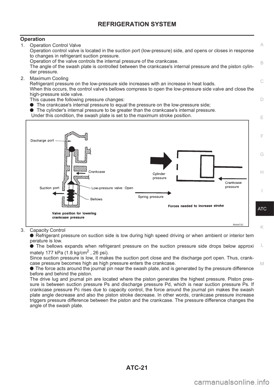
Operation
1. Operation Control Valve
Operation control valve is located in the suction port (low-pressure) side, and opens or closes in response
to changes in refrigerant suction pressure.
Operation of the valve controls the internal pressure of the crankcase.
The angle of the swash plate is controlled between the crankcase's internal pressure and the piston cylin-
der pressure.
2. Maximum Cooling
Refrigerant pressure on the low-pressure side increases with an increase in heat loads.
When this occurs, the control valve's bellows compress to open the low-pressure side valve and close the
high-pressure side valve.
This causes the following pressure changes:
● The crankcase's internal pressure to equal the pressure on the low-pressure side;
● The cylinder's internal pressure to be greater than the crankcase's internal pressure.
Under this condition, the swash plate is set to the maximum stroke position.
3. Capacity Control
● Refrigerant pressure on suction side is low during high speed driving or when ambient or interior tem
perature is low.
● The bellows expands when refrigerant pressure on the suction pressure side drops below approxi
mately 177 kPa (1.8 kg/cm
2 , 26 psi).
Since suction pressure is low, it makes the suction port close and the discharge port open. Thus, crank-
case pressure becomes high as high pressure enters the crankcase.
● The force acts around the journal pin near the swash plate, and is generated by the pressure difference
before and behind the piston.
The drive lug and journal pin are located where the piston generates the highest pressure. Piston pres-
sure is between suction pressure Ps and discharge pressure Pd, which is near suction pressure Ps. If
crankcase pressure Pc rises due to capacity control, the force around the journal pin makes the swash
plate angle decrease and also the piston stroke decrease. In other words, crankcase pressure increase
triggers pressure difference between the piston and the crankcase. The pressure difference changes the
angle of the swash plate.
RHA473C
Page 3300 of 3833
ATC-24
LUBRICANT
LUBRICANT
PFP:KLG00
Maintenance of Lubricant Quantity in CompressorEJS000TH
The lubricant in the compressor circulates through the system with the refrigerant. Add lubricant to compres-
sor when replacing any component or after a large gas leakage occurred. It is important to maintain the speci-
fied amount.
If lubricant quantity is not maintained properly, the following malfunctions may result:
●Lack of lubricant: May lead to a seized compressor
●Excessive lubricant: Inadequate cooling (thermal exchange interference)
LUBRICANT
LUBRICANT RETURN OPERATION
Adjust the lubricant quantity according to the test group shown below.
1. CHECK LUBRICANT RETURN OPERATION
Can lubricant return operation be performed?
●A/C system works properly.
●There is no evidence of a large amount of lubricant leakage.
YES or NO
YES >> GO TO 2.
NO >> GO TO 3.
2. PERFORM LUBRICANT RETURN OPERATION, PROCEEDING AS FOLLOWS:
1. Start engine, and set the following conditions:
–Test condition
Engine speed: Idling to 1,200 rpm
A/C or AUTO switch: ON
Blower speed: Max. position
Temp. control: Optional [Set so that intake air temperature is 25 to 30°C (77 to 86°F).]
Intake position: Recirculation (REC)
2. Perform lubricant return operation for about 10 minutes.
3. Stop engine.
CAUTION:
If excessive lubricant leakage is noted, do not perform the lubricant return operation.
>> GO TO 3.
3. CHECK COMPRESSOR
Should the compressor be replaced?
YES or NO
YES >> Go to AT C - 2 5 , "LUBRICANT ADJUSTING PROCEDURE FOR COMPRESSOR REPLACE-
MENT" .
NO >> GO TO 4.With gasoline engine
(CWV-615M Compressor)With diesel engine
(DKV-11G Compressor)
Name Nissan A/C System Oil Type S Nissan A/C System Oil Type R
Part number KLH00-PAGS0 KLH00-PAGR0
Page 3309 of 3833
TROUBLE DIAGNOSIS
ATC-33
C
D
E
F
G
H
I
K
L
MA
B
AT C
TROUBLE DIAGNOSISPFP:00004
How to Perform Trouble Diagnoses for Quick and Accurate RepairEJS001GS
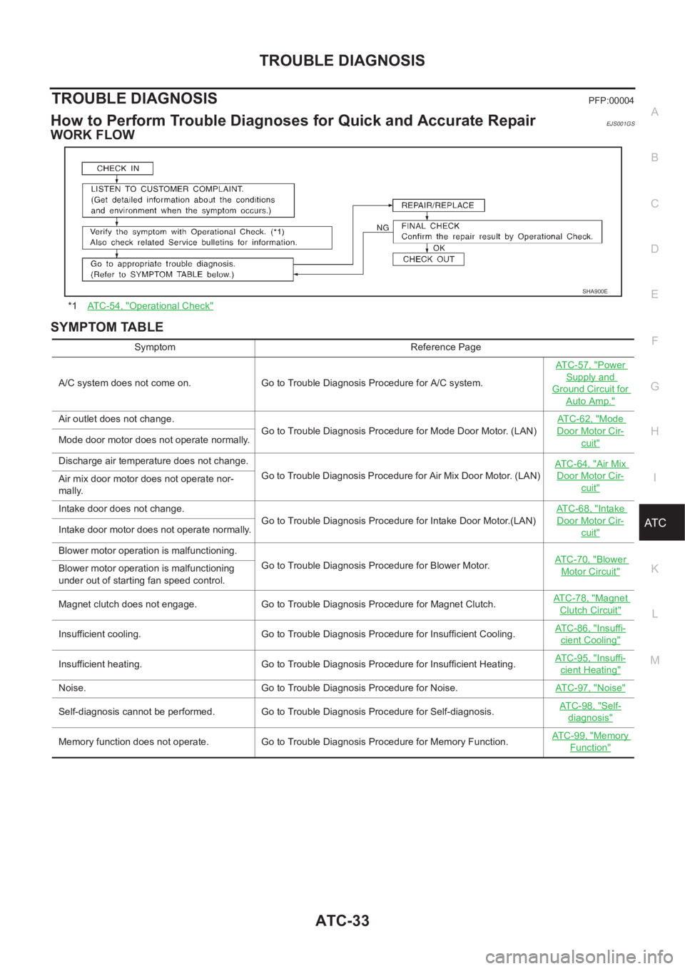
WORK FLOW
SYMPTOM TABLE
*1AT C - 5 4 , "Operational Check"
SHA900E
Symptom Reference Page
A/C system does not come on. Go to Trouble Diagnosis Procedure for A/C system.ATC-57, "
Power
Supply and
Ground Circuit for
Auto Amp."
Air outlet does not change.
Go to Trouble Diagnosis Procedure for Mode Door Motor. (LAN)AT C - 6 2 , "Mode
Door Motor Cir-
cuit"Mode door motor does not operate normally.
Discharge air temperature does not change.
Go to Trouble Diagnosis Procedure for Air Mix Door Motor. (LAN)ATC-64, "
Air Mix
Door Motor Cir-
cuit"Air mix door motor does not operate nor-
mally.
Intake door does not change.
Go to Trouble Diagnosis Procedure for Intake Door Motor.(LAN)AT C - 6 8 , "
Intake
Door Motor Cir-
cuit"Intake door motor does not operate normally.
Blower motor operation is malfunctioning.
Go to Trouble Diagnosis Procedure for Blower Motor.ATC-70, "
Blower
Motor Circuit"Blower motor operation is malfunctioning
under out of starting fan speed control.
Magnet clutch does not engage. Go to Trouble Diagnosis Procedure for Magnet Clutch.AT C - 7 8 , "
Magnet
Clutch Circuit"
Insufficient cooling. Go to Trouble Diagnosis Procedure for Insufficient Cooling.AT C - 8 6 , "Insuffi-
cient Cooling"
Insufficient heating. Go to Trouble Diagnosis Procedure for Insufficient Heating.AT C - 9 5 , "Insuffi-
cient Heating"
Noise. Go to Trouble Diagnosis Procedure for Noise.ATC-97, "Noise"
Self-diagnosis cannot be performed. Go to Trouble Diagnosis Procedure for Self-diagnosis.AT C - 9 8 , "Self-
diagnosis"
Memory function does not operate. Go to Trouble Diagnosis Procedure for Memory Function.AT C - 9 9 , "Memory
Function"
Page 3332 of 3833
ATC-56
TROUBLE DIAGNOSIS
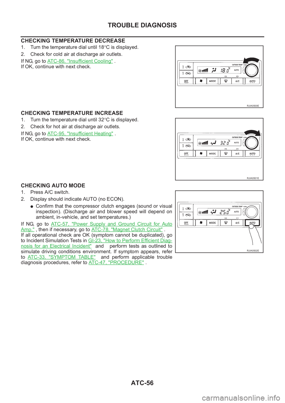
CHECKING TEMPERATURE DECREASE
1. Turn the temperature dial until 18°C is displayed.
2. Check for cold air at discharge air outlets.
If NG, go to AT C - 8 6 , "
Insufficient Cooling" .
If OK, continue with next check.
CHECKING TEMPERATURE INCREASE
1. Turn the temperature dial until 32°C is displayed.
2. Check for hot air at discharge air outlets.
If NG, go to AT C - 9 5 , "
Insufficient Heating" .
If OK, continue with next check.
CHECKING AUTO MODE
1. Press A/C switch.
2. Display should indicate AUTO (no ECON).
●Confirm that the compressor clutch engages (sound or visual
inspection). (Discharge air and blower speed will depend on
ambient, in-vehicle, and set temperatures.)
If NG, go to AT C - 5 7 , "
Power Supply and Ground Circuit for Auto
Amp." , then if necessary, go to AT C - 7 8 , "Magnet Clutch Circuit" .
If all operational check are OK (symptom cannot be duplicated), go
to Incident Simulation Tests in GI-23, "
How to Perform Efficient Diag-
nosis for an Electrical Incident" and perform tests as outlined to
simulate driving conditions environment. If symptom appears, refer
to AT C - 3 3 , "
SYMPTOM TABLE" and perform applicable trouble
diagnosis procedures, refer to ATC-47, "
PROCEDURE" .
RJIA0500E
RJIA0501E
RJIA0502E
Page 3340 of 3833
ATC-64
TROUBLE DIAGNOSIS
COMPONENT DESCRIPTION
Mode Door Motor
The mode door motor is attached to the heater & cooling unit. It
rotates so that air is discharged from the outlet set by the auto ampli-
fier. Motor rotation is conveyed to a link which activates the mode
door.
DIAGNOSTIC PROCEDURE
SYMPTOM: Mode door motor and/or air mix door motor does not operate normally.
Perform diagnostic procedure for ATC-59, "
LAN System Circuit" .
Air Mix Door Motor CircuitEJS002FQ
SYMPTOM:
●Discharge air temperature does not change.
●Air mix door motor does not operate.
RJIA0513E
RJIA0514E
Page 3342 of 3833
ATC-66
TROUBLE DIAGNOSIS
SYSTEM DESCRIPTION
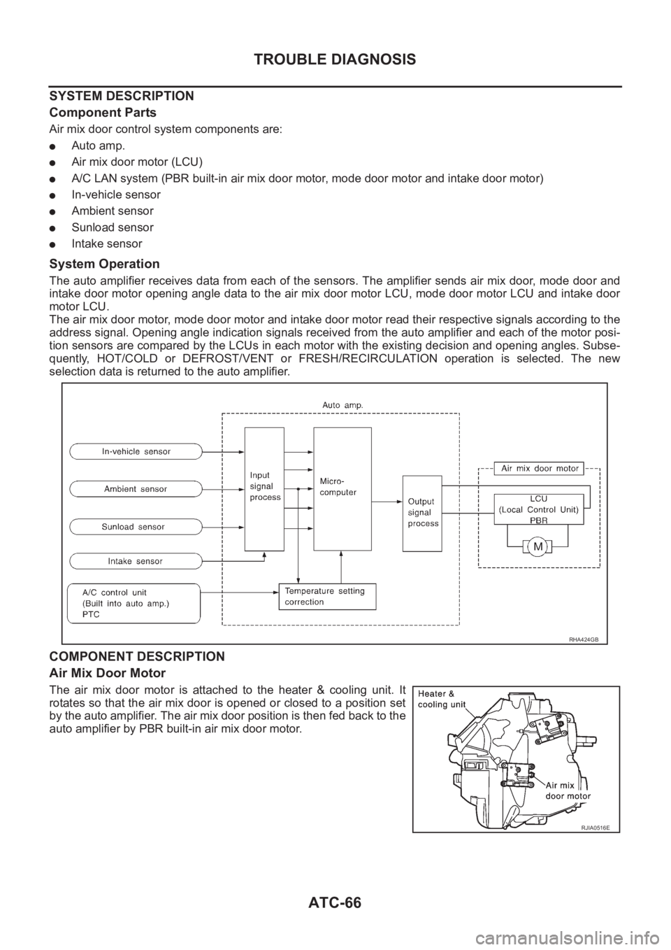
Component Parts
Air mix door control system components are:
●Auto amp.
●Air mix door motor (LCU)
●A/C LAN system (PBR built-in air mix door motor, mode door motor and intake door motor)
●In-vehicle sensor
●Ambient sensor
●Sunload sensor
●Intake sensor
System Operation
The auto amplifier receives data from each of the sensors. The amplifier sends air mix door, mode door and
intake door motor opening angle data to the air mix door motor LCU, mode door motor LCU and intake door
motor LCU.
The air mix door motor, mode door motor and intake door motor read their respective signals according to the
address signal. Opening angle indication signals received from the auto amplifier and each of the motor posi-
tion sensors are compared by the LCUs in each motor with the existing decision and opening angles. Subse-
quently, HOT/COLD or DEFROST/VENT or FRESH/RECIRCULATION operation is selected. The new
selection data is returned to the auto amplifier.
COMPONENT DESCRIPTION
Air Mix Door Motor
The air mix door motor is attached to the heater & cooling unit. It
rotates so that the air mix door is opened or closed to a position set
by the auto amplifier. The air mix door position is then fed back to the
auto amplifier by PBR built-in air mix door motor.
RHA424GB
RJIA0516E