2001 NISSAN X-TRAIL check engine
[x] Cancel search: check enginePage 340 of 3833
![NISSAN X-TRAIL 2001 Service Repair Manual CO-34
[YD22DDTi]
RADIATOR
●Check radiator cap relief pressure.
●When connecting the radiator cap to the tester, apply engine
coolant to the cap seal part.
●Replace the radiator cap if NISSAN X-TRAIL 2001 Service Repair Manual CO-34
[YD22DDTi]
RADIATOR
●Check radiator cap relief pressure.
●When connecting the radiator cap to the tester, apply engine
coolant to the cap seal part.
●Replace the radiator cap if](/manual-img/5/57405/w960_57405-339.png)
CO-34
[YD22DDTi]
RADIATOR
●Check radiator cap relief pressure.
●When connecting the radiator cap to the tester, apply engine
coolant to the cap seal part.
●Replace the radiator cap if there is an unusualness in the nega-
tive-pressure valve, or if the open-valve pressure is outside of
the standard values.
Checking RadiatorEBS00BRH
Check radiator for mud or clogging. If necessary, clean radiator as follows.
●Be careful not to bend or damage the radiator fins.
●When radiator is cleaned without removal, remove all surrounding parts such as cooling fan, radiator
shroud and horns. Then tape the harness and connectors to prevent water from entering.
1. Apply water by hose to the back side of the radiator core vertically downwards.
2. Apply water again to all radiator core surface once per minute.
3. Stop washing if any stains no longer flow out from the radiator.
4. Blow air into the back side of radiator core vertically downwards.
●Use compressed air lower than 490 kPa (4.9 bar 5 kg/cm2 , 71psi) and keep distance more than 30
cm(11.8 in).
5. Blow air again into all the radiator core surface once per minute until no water sprays out. Standard : 78 - 98 kPa (0.78 - 0.98 bar, 0.8 - 1.0 kg/
cm
2 , 11 - 14 psi)
Limit : 59 kPa (0.59 bar, 0.6 kg/cm
2 , 9 psi)
SLC135B
Page 345 of 3833
![NISSAN X-TRAIL 2001 Service Repair Manual WATER PUMP
CO-39
[YD22DDTi]
C
D
E
F
G
H
I
J
K
L
MA
CO
WAT E R P U MPPFP:21020
Removal and InstallationEBS00BB4
WARNING:
Never remove the radiator cap when the engine is hot. Serious burns could occur NISSAN X-TRAIL 2001 Service Repair Manual WATER PUMP
CO-39
[YD22DDTi]
C
D
E
F
G
H
I
J
K
L
MA
CO
WAT E R P U MPPFP:21020
Removal and InstallationEBS00BB4
WARNING:
Never remove the radiator cap when the engine is hot. Serious burns could occur](/manual-img/5/57405/w960_57405-344.png)
WATER PUMP
CO-39
[YD22DDTi]
C
D
E
F
G
H
I
J
K
L
MA
CO
WAT E R P U MPPFP:21020
Removal and InstallationEBS00BB4
WARNING:
Never remove the radiator cap when the engine is hot. Serious burns could occur from high pressure
engine coolant escaping from the radiator.
REMOVAL
1. Remove the under cover, splash cover (right), and drive belt.
2. Drain engine coolant. Refer to CO-29, "
DRAINING ENGINE COOLANT" .
CAUTION:
Perform when the engine is cold.
3. Support the bottom of the oil pan with a floor jack etc, and remove the right engine mount bracket (front
side of the engine).
4. Remove the water pump pulley.
●Loosen the pulley bolts after fixing the pulley using a screwdriver etc.
5. Remove engine mount bracket.
6. Remove the water pump.
●Engine coolant will leak from the cylinder block, so have a receptacle ready below.
CAUTION:
●Handle the water pump vane so that it does not contact any other parts.
●Water pump cannot be disassembled and should be replaced as a unit.
INSPECTION AFTER REMOVAL
●Visually check that there is no significant dirt or rusting on the
water pump body and vane.
●Check that there is no looseness in the vane shaft, and that it
turns smoothly when rotated by hand.
●If there are any unusualness, replace the water pump assembly.
JLC294B
SBIA0132E
Page 346 of 3833
![NISSAN X-TRAIL 2001 Service Repair Manual CO-40
[YD22DDTi]
WATER PUMP
INSTALLATION
●Install in the reverse order of removal
●Install the water pump pulley with the front mark (painted white, used to prevent errors during assembly)
facing NISSAN X-TRAIL 2001 Service Repair Manual CO-40
[YD22DDTi]
WATER PUMP
INSTALLATION
●Install in the reverse order of removal
●Install the water pump pulley with the front mark (painted white, used to prevent errors during assembly)
facing](/manual-img/5/57405/w960_57405-345.png)
CO-40
[YD22DDTi]
WATER PUMP
INSTALLATION
●Install in the reverse order of removal
●Install the water pump pulley with the front mark (painted white, used to prevent errors during assembly)
facing the front of the engine. Refer to the figure above.
INSPECTION AFTER INSTALLATION
Check for engine coolant leaks using radiator cap tester. Refer to CO-29, "CHECKING RADIATOR SYSTEM
FOR LEAKS" .
Page 351 of 3833

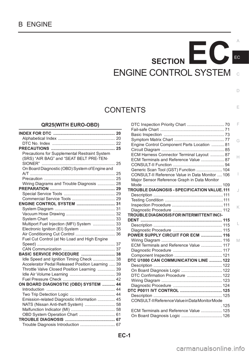
EC-1
ENGINE CONTROL SYSTEM
B ENGINE
CONTENTS
C
D
E
F
G
H
I
J
K
L
M
SECTION
A
EC
ENGINE CONTROL SYSTEM
QR25(WITH EURO-OBD)
INDEX FOR DTC ...................................................... 20
Alphabetical Index .................................................. 20
DTC No. Index ....................................................... 22
PRECAUTIONS ........................................................ 25
Precautions for Supplemental Restraint System
(SRS) “AIR BAG” and “SEAT BELT PRE-TEN-
SIONER” ................................................................ 25
On Board Diagnostic (OBD) System of Engine and
A/T .......................................................................... 25
Precaution .............................................................. 25
Wiring Diagrams and Trouble Diagnosis ................ 28
PREPARATION ......................................................... 29
Special Service Tools ............................................. 29
Commercial Service Tools ...................................... 29
ENGINE CONTROL SYSTEM .................................. 31
System Diagram ..................................................... 31
Vacuum Hose Drawing ........................................... 32
System Chart ......................................................... 33
Multiport Fuel Injection (MFI) System .................... 33
Electronic Ignition (EI) System ............................... 35
Air Conditioning Cut Control ................................... 36
Fuel Cut Control (at No Load and High Engine
Speed) .................................................................... 37
CAN Communication .............................................. 37
BASIC SERVICE PROCEDURE .............................. 38
Idle Speed and Ignition Timing Check .................... 38
Accelerator Pedal Released Position Learning ...... 39
Throttle Valve Closed Position Learning ................ 39
Idle Air Volume Learning ........................................ 39
Fuel Pressure Check .............................................. 42
ON BOARD DIAGNOSTIC (OBD) SYSTEM ............ 44
Introduction ............................................................ 44
Two Trip Detection Logic ........................................ 44
Emission-related Diagnostic Information ................ 45
NATS (Nissan Anti-theft System) ........................... 58
Malfunction Indicator (MI) ....................................... 58
OBD System Operation Chart ................................ 61
TROUBLE DIAGNOSIS ............................................ 67
Trouble Diagnosis Introduction ............................... 67DTC Inspection Priority Chart ................................. 70
Fail-safe Chart ........................................................ 71
Basic Inspection ..................................................... 73
Symptom Matrix Chart ............................................ 77
Engine Control Component Parts Location ............ 81
Circuit Diagram ....................................................... 85
ECM Harness Connector Terminal Layout ............. 87
ECM Terminals and Reference Value ..................
... 87
CONSULT-II Function ............................................. 94
Generic Scan Tool (GST) Function .......................104
CONSULT-II Reference Value in Data Monitor .....106
Major Sensor Reference Graph in Data Monitor
Mode .....................................................................109
TROUBLE DIAGNOSIS - SPECIFICATION VALUE ..111
Description .............................................................111
Testing Condition ...................................................111
Inspection Procedure .............................................111
Diagnostic Procedure ...........................................112
TROUBLE DIAGNOSIS FOR INTERMITTENT INCI-
DENT .......................................................................115
Description ............................................................115
Diagnostic Procedure ...........................................115
POWER SUPPLY CIRCUIT FOR ECM ...................116
Wiring Diagram .....................................................116
ECM Terminals and Reference Value ...................117
Diagnostic Procedure ...........................................117
Component Inspection ..........................................121
DTC U1000 CAN COMMUNICATION LINE ............122
Description ............................................................122
On Board Diagnosis Logic ....................................122
DTC Confirmation Procedure ...............................122
Wiring Diagram .....................................................123
Diagnostic Procedure ...........................................124
DTC P0011 IVT CONTROL .....................................125
Description ............................................................125
CONSULT-II Reference Value in Data Monitor Mode
.125
ECM Terminals and Reference Value ...................125
On Board Diagnosis Logic ....................................126
Page 354 of 3833

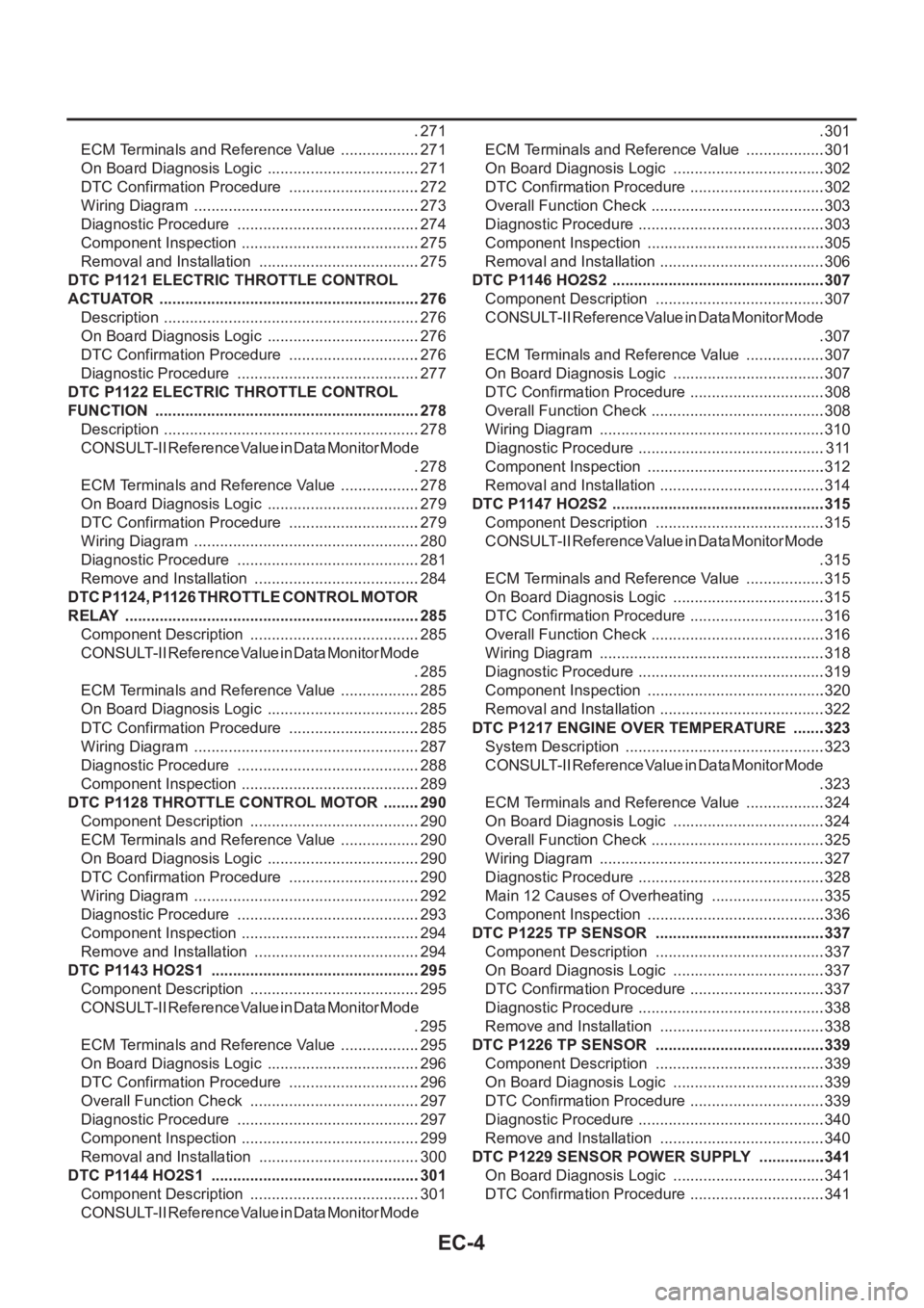
EC-4
.271
ECM Terminals and Reference Value ...................271
On Board Diagnosis Logic ....................................271
DTC Confirmation Procedure ...............................272
Wiring Diagram .....................................................273
Diagnostic Procedure ...........................................274
Component Inspection ..........................................275
Removal and Installation ......................................275
DTC P1121 ELECTRIC THROTTLE CONTROL
ACTUATOR .............................................................276
Description ............................................................276
On Board Diagnosis Logic ....................................276
DTC Confirmation Procedure ...............................276
Diagnostic Procedure ...........................................277
DTC P1122 ELECTRIC THROTTLE CONTROL
FUNCTION ..............................................................278
Description ............................................................278
CONSULT-II Reference Value in Data Monitor Mode
.278
ECM Terminals and Reference Value ...................278
On Board Diagnosis Logic ....................................279
DTC Confirmation Procedure ...............................279
Wiring Diagram .....................................................280
Diagnostic Procedure ...........................................281
Remove and Installation .......................................284
DTC P1124, P1126 THROTTLE CONTROL MOTOR
RELAY .....................................................................285
Component Description ........................................285
CONSULT-II Reference Value in Data Monitor Mode
.285
ECM Terminals and Reference Value ...................285
On Board Diagnosis Logic ....................................285
DTC Confirmation Procedure ...............................285
Wiring Diagram .....................................................287
Diagnostic Procedure ...........................................288
Component Inspection ..........................................289
DTC P1128 THROTTLE CONTROL MOTOR .........290
Component Description ........................................290
ECM Terminals and Reference Value ...................290
On Board Diagnosis Logic ....................................290
DTC Confirmation Procedure ...............................290
Wiring Diagram .....................................................292
Diagnostic Procedure ...........................................293
Component Inspection ..........................................294
Remove and Installation .......................................294
DTC P1143 HO2S1 .................................................295
Component Description ........................................295
CONSULT-II Reference Value in Data Monitor Mode
.295
ECM Terminals and Reference Value ...................295
On Board Diagnosis Logic ....................................296
DTC Confirmation Procedure ...............................296
Overall Function Check ........................................297
Diagnostic Procedure ...........................................297
Component Inspection ..........................................299
Removal and Installation ......................................300
DTC P1144 HO2S1 .................................................301
Component Description ........................................301
CONSULT-II Reference Value in Data Monitor Mode .301
ECM Terminals and Reference Value ...................301
On Board Diagnosis Logic ....................................302
DTC Confirmation Procedure ................................302
Overall Function Check .........................................303
Diagnostic Procedure ............................................303
Component Inspection ..........................................305
Removal and Installation .......................................306
DTC P1146 HO2S2 ..................................................307
Component Description ........................................307
CONSULT-II Reference Value in Data Monitor Mode
.307
ECM Terminals and Reference Value ...................307
On Board Diagnosis Logic ....................................307
DTC Confirmation Procedure ................................308
Overall Function Check .........................................308
Wiring Diagram .....................................................310
Diagnostic Procedure ............................................311
Component Inspection ..........................................312
Removal and Installation .......................................314
DTC P1147 HO2S2 ..................................................315
Component Description ........................................315
CONSULT-II Reference Value in Data Monitor Mode
.315
ECM Terminals and Reference Value ...................315
On Board Diagnosis Logic ....................................315
DTC Confirmation Procedure ................................316
Overall Function Check .........................................316
Wiring Diagram .....................................................318
Diagnostic Procedure ............................................319
Component Inspection ..........................................320
Removal and Installation .......................................322
DTC P1217 ENGINE OVER TEMPERATURE ........323
System Description ...............................................323
CONSULT-II Reference Value in Data Monitor Mode
.323
ECM Terminals and Reference Value ...................324
On Board Diagnosis Logic ....................................324
Overall Function Check .........................................325
Wiring Diagram .....................................................327
Diagnostic Procedure ............................................328
Main 12 Causes of Overheating ...........................335
Component Inspection ..........................................336
DTC P1225 TP SENSOR ........................................337
Component Description ........................................337
On Board Diagnosis Logic ....................................337
DTC Confirmation Procedure ................................337
Diagnostic Procedure ............................................338
Remove and Installation .......................................338
DTC P1226 TP SENSOR ........................................339
Component Description ........................................339
On Board Diagnosis Logic ....................................339
DTC Confirmation Procedure ................................339
Diagnostic Procedure ............................................340
Remove and Installation .......................................340
DTC P1229 SENSOR POWER SUPPLY ................341
On Board Diagnosis Logic ....................................341
DTC Confirmation Procedure ................................341
Page 356 of 3833

EC-6
DATA LINK CONNECTOR ......................................424
Wiring Diagram .....................................................424
EVAPORATIVE EMISSION SYSTEM .....................425
Description ............................................................425
Component Inspection ..........................................427
POSITIVE CRANKCASE VENTILATION ...............428
Description ............................................................428
Component Inspection ..........................................428
SERVICE DATA AND SPECIFICATIONS (SDS) ....430
Fuel Pressure .......................................................430
Idle Speed and Ignition Timing .............................430
Calculated Load Value ..........................................430
Mass Air Flow Sensor ...........................................430
Intake Air Temperature Sensor .............................430
Engine Coolant Temperature Sensor ...................430
Heated Oxygen Sensor 1 Heater .........................430
Heated Oxygen sensor 2 Heater ..........................430
Crankshaft Position Sensor (POS) .......................430
Camshaft Position Sensor (PHASE) ....................431
Throttle Control Motor ...........................................431
Injector ..................................................................431
Fuel Pump ............................................................431
QR25(WITHOUT EURO-OBD)
INDEX FOR DTC .....................................................432
Alphabetical Index ................................................432
DTC No. Index ......................................................433
PRECAUTIONS .......................................................435
Precautions for Supplemental Restraint System
(SRS) “AIR BAG” and “SEAT BELT PRE-TEN-
SIONER” ...............................................................435
On Board Diagnostic (OBD) System of Engine and
A/T ........................................................................435
Precaution ............................................................435
Wiring Diagrams and Trouble Diagnosis ..............438
PREPARATION .......................................................439
Special Service Tools ...........................................439
Commercial Service Tools ....................................439
ENGINE CONTROL SYSTEM ................................441
System Diagram ...................................................441
Vacuum Hose Drawing .........................................442
System Chart ........................................................443
Multiport Fuel Injection (MFI) System ...................443
Electronic Ignition (EI) System .............................445
Air Conditioning Cut Control .................................446
Fuel Cut Control (at No Load and High Engine
Speed) ..................................................................447
CAN Communication ............................................447
BASIC SERVICE PROCEDURE .............................448
Idle Speed and Ignition Timing Check ..................448
Accelerator Pedal Released Position Learning ....449
Throttle Valve Closed Position Learning ...............449
Idle Air Volume Learning ......................................450
Fuel Pressure Check ............................................452
ON BOARD DIAGNOSTIC (OBD) SYSTEM ..........454
Introduction ...........................................................454
Two Trip Detection Logic ......................................454
Emission-related Diagnostic Information ..............454NATS (Nissan Anti-theft System) ..........................456
Malfunction Indicator (MI) .....................................457
TROUBLE DIAGNOSIS ..........................................460
Trouble Diagnosis Introduction .............................460
DTC Inspection Priority Chart ...............................463
Fail-safe Chart ......................................................464
Basic Inspection ....................................................465
Symptom Matrix Chart ..........................................469
Engine Control Component Parts Location ...........473
Circuit Diagram .....................................................477
ECM Harness Connector Terminal Layout ............479
ECM Terminals and Reference Value ...................479
CONSULT-II Function ...........................................486
CONSULT-II Reference Value in Data Monitor .....496
Major Sensor Reference Graph in Data Monitor
Mode .....................................................................499
TROUBLE DIAGNOSIS - SPECIFICATION VALUE .502
Description ............................................................502
Testing Condition ..................................................502
Inspection Procedure ........................................... .502
Diagnostic Procedure ............................................503
TROUBLE DIAGNOSIS FOR INTERMITTENT INCI-
DENT .......................................................................506
Description ............................................................506
Diagnostic Procedure ............................................506
POWER SUPPLY CIRCUIT FOR ECM ...................507
Wiring Diagram .....................................................507
ECM Terminals and Reference Value ...................508
Diagnostic Procedure ............................................508
Component Inspection ..........................................512
DTC U1000 CAN COMMUNICATION LINE ............513
Description ............................................................513
On Board Diagnosis Logic ....................................513
DTC Confirmation Procedure ................................513
Wiring Diagram .....................................................514
Diagnostic Procedure ............................................515
DTC P0102, P0103 MAF SENSOR .........................516
Component Description ........................................516
CONSULT-II Reference Value in Data Monitor Mode
.516
ECM Terminals and Reference Value ...................516
On Board Diagnosis Logic ....................................516
DTC Confirmation Procedure ................................517
Wiring Diagram .....................................................519
Diagnostic Procedure ............................................520
Component Inspection ..........................................522
Removal and Installation .......................................522
DTC P0117, P0118 ECT SENSOR ..........................523
Component Description ........................................523
On Board Diagnosis Logic ....................................523
DTC Confirmation Procedure ................................524
Wiring Diagram .....................................................525
Diagnostic Procedure ............................................526
Component Inspection ..........................................527
Removal and Installation .......................................527
DTC P0122, P0123 TP SENSOR ............................528
Component Description ........................................528
CONSULT-II Reference Value in Data Monitor Mode
.528
Page 358 of 3833

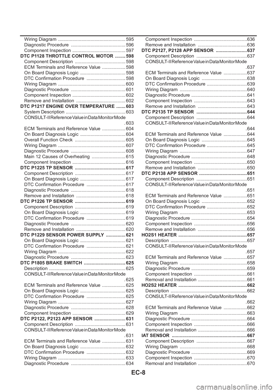
EC-8
Wiring Diagram .....................................................595
Diagnostic Procedure ...........................................596
Component Inspection ..........................................597
DTC P1128 THROTTLE CONTROL MOTOR .........598
Component Description ........................................598
ECM Terminals and Reference Value ...................598
On Board Diagnosis Logic ....................................598
DTC Confirmation Procedure ...............................598
Wiring Diagram .....................................................600
Diagnostic Procedure ...........................................601
Component Inspection ..........................................602
Remove and Installation .......................................602
DTC P1217 ENGINE OVER TEMPERATURE ........603
System Description ...............................................603
CONSULT-II Reference Value in Data Monitor Mode
.603
ECM Terminals and Reference Value ...................604
On Board Diagnosis Logic ....................................604
Overall Function Check ........................................605
Wiring Diagram .....................................................607
Diagnostic Procedure ...........................................608
Main 12 Causes of Overheating ...........................615
Component Inspection ..........................................616
DTC P1225 TP SENSOR ........................................617
Component Description ........................................617
On Board Diagnosis Logic ....................................617
DTC Confirmation Procedure ...............................617
Diagnostic Procedure ...........................................618
Remove and Installation .......................................618
DTC P1226 TP SENSOR ........................................619
Component Description ........................................619
On Board Diagnosis Logic ....................................619
DTC Confirmation Procedure ...............................619
Diagnostic Procedure ...........................................620
Remove and Installation .......................................620
DTC P1229 SENSOR POWER SUPPLY ................621
On Board Diagnosis Logic ....................................621
DTC Confirmation Procedure ...............................621
Wiring Diagram .....................................................622
Diagnostic Procedure ...........................................623
DTC P1805 BRAKE SWITCH .................................625
Description ............................................................625
CONSULT-II Reference Value in Data Monitor Mode
.625
ECM Terminals and Reference Value ...................625
On Board Diagnosis Logic ....................................625
DTC Confirmation Procedure ...............................625
Wiring Diagram .....................................................627
Diagnostic Procedure ...........................................628
Component Inspection ..........................................629
DTC P2122, P2123 APP SENSOR .........................631
Component Description ........................................631
CONSULT-II Reference Value in Data Monitor Mode
.631
ECM Terminals and Reference Value ...................631
On Board Diagnosis Logic ....................................632
DTC Confirmation Procedure ...............................632
Wiring Diagram .....................................................633
Diagnostic Procedure ...........................................634Component Inspection ..........................................636
Remove and Installation .......................................636
DTC P2127, P2128 APP SENSOR .........................637
Component Description ........................................637
CONSULT-II Reference Value in Data Monitor Mode
.637
ECM Terminals and Reference Value ...................637
On Board Diagnosis Logic ....................................638
DTC Confirmation Procedure ................................639
Wiring Diagram .....................................................640
Diagnostic Procedure ............................................641
Component Inspection ..........................................643
Remove and Installation .......................................643
DTC P2135 TP SENSOR ........................................644
Component Description ........................................644
CONSULT-II Reference Value in Data Monitor Mode
.644
ECM Terminals and Reference Value ...................644
On Board Diagnosis Logic ....................................645
DTC Confirmation Procedure ................................645
Wiring Diagram .....................................................647
Diagnostic Procedure ............................................648
Component Inspection ..........................................650
Remove and Installation .......................................650
DTC P2138 APP SENSOR ......................................651
Component Description ........................................651
CONSULT-II Reference Value in Data Monitor Mode
.651
ECM Terminals and Reference Value ...................651
On Board Diagnosis Logic ....................................652
DTC Confirmation Procedure ................................652
Wiring Diagram .....................................................653
Diagnostic Procedure ............................................654
Component Inspection ..........................................656
Remove and Installation .......................................656
HO2S1 HEATER ......................................................657
Description ............................................................657
CONSULT-II Reference Value in Data Monitor Mode
.657
ECM Terminals and Reference Value ...................657
Wiring Diagram ....................................................
.658
Diagnostic Procedure ............................................659
Component Inspection ..........................................661
Removal and Installation .......................................661
HO2S2 HEATER ......................................................662
Description ............................................................662
CONSULT-II Reference Value in Data Monitor Mode
.662
ECM Terminals and Reference Value ...................662
Wiring Diagram .....................................................663
Diagnostic Procedure ............................................664
Component Inspection ..........................................666
Removal and Installation .......................................666
IAT SENSOR ...........................................................667
Component Description ........................................667
Wiring Diagram .....................................................668
Diagnostic Procedure ............................................669
Component Inspection ..........................................670
Removal and Installation .......................................670
Page 360 of 3833

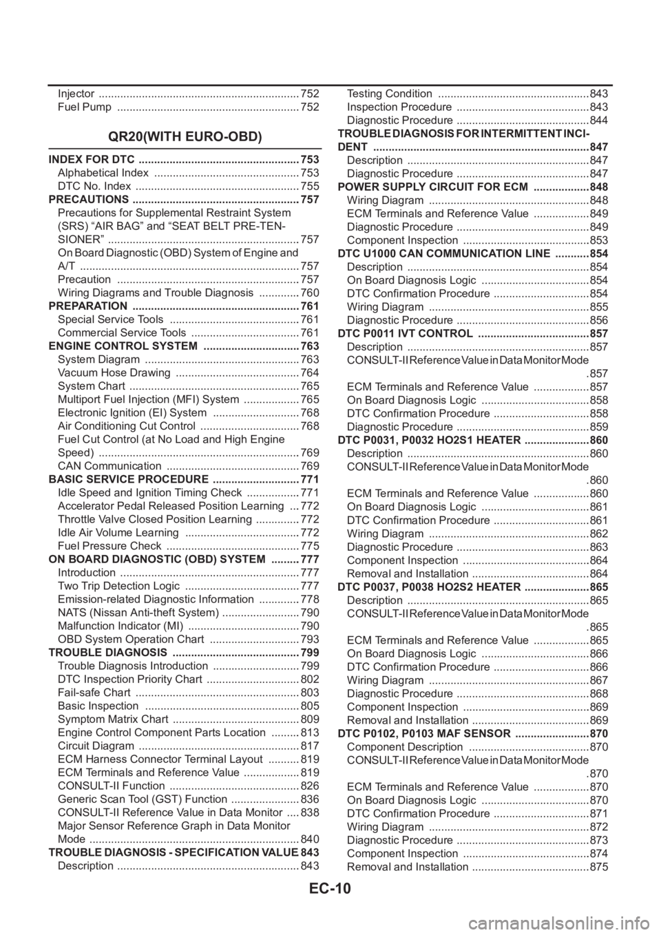
EC-10
Injector ..................................................................752
Fuel Pump ............................................................752
QR20(WITH EURO-OBD)
INDEX FOR DTC .....................................................753
Alphabetical Index ................................................753
DTC No. Index ......................................................755
PRECAUTIONS .......................................................757
Precautions for Supplemental Restraint System
(SRS) “AIR BAG” and “SEAT BELT PRE-TEN-
SIONER” ...............................................................757
On Board Diagnostic (OBD) System of Engine and
A/T ........................................................................757
Precaution ............................................................757
Wiring Diagrams and Trouble Diagnosis ..............760
PREPARATION .......................................................761
Special Service Tools ...........................................761
Commercial Service Tools ....................................761
ENGINE CONTROL SYSTEM ................................763
System Diagram ...................................................763
Vacuum Hose Drawing .........................................764
System Chart ........................................................765
Multiport Fuel Injection (MFI) System ...................765
Electronic Ignition (EI) System .............................768
Air Conditioning Cut Control .................................768
Fuel Cut Control (at No Load and High Engine
Speed) ..................................................................769
CAN Communication ............................................769
BASIC SERVICE PROCEDURE .............................771
Idle Speed and Ignition Timing Check ..................771
Accelerator Pedal Released Position Learning ....772
Throttle Valve Closed Position Learning ...............772
Idle Air Volume Learning ......................................772
Fuel Pressure Check ............................................775
ON BOARD DIAGNOSTIC (OBD) SYSTEM ..........777
Introduction ...........................................................777
Two Trip Detection Logic ......................................777
Emission-related Diagnostic Information ..............778
NATS (Nissan Anti-theft System) ..........................790
Malfunction Indicator (MI) .....................................790
OBD System Operation Chart ..............................793
TROUBLE DIAGNOSIS ..........................................799
Trouble Diagnosis Introduction .............................799
DTC Inspection Priority Chart ...............................802
Fail-safe Chart ......................................................803
Basic Inspection ...................................................805
Symptom Matrix Chart ..........................................809
Engine Control Component Parts Location ..........813
Circuit Diagram .....................................................817
ECM Harness Connector Terminal Layout ...........819
ECM Terminals and Reference Value ...................819
CONSULT-II Function ...........................................826
Generic Scan Tool (GST) Function .......................836
CONSULT-II Reference Value in Data Monitor .....838
Major Sensor Reference Graph in Data Monitor
Mode .....................................................................840
TROUBLE DIAGNOSIS - SPECIFICATION VALUE .843
Description ............................................................843Testing Condition ..................................................843
Inspection Procedure ........................................... .843
Diagnostic Procedure ............................................844
TROUBLE DIAGNOSIS FOR INTERMITTENT INCI-
DENT .......................................................................847
Description ............................................................847
Diagnostic Procedure ............................................847
POWER SUPPLY CIRCUIT FOR ECM ...................848
Wiring Diagram .....................................................848
ECM Terminals and Reference Value ...................849
Diagnostic Procedure ............................................849
Component Inspection ..........................................853
DTC U1000 CAN COMMUNICATION LINE ............854
Description ............................................................854
On Board Diagnosis Logic ....................................854
DTC Confirmation Procedure ................................854
Wiring Diagram .....................................................855
Diagnostic Procedure ............................................856
DTC P0011 IVT CONTROL .....................................857
Description ............................................................857
CONSULT-II Reference Value in Data Monitor Mode
.857
ECM Terminals and Reference Value ...................857
On Board Diagnosis Logic ....................................858
DTC Confirmation Procedure ................................858
Diagnostic Procedure ............................................859
DTC P0031, P0032 HO2S1 HEATER ......................860
Description ............................................................860
CONSULT-II Reference Value in Data Monitor Mode
.860
ECM Terminals and Reference Value ...................860
On Board Diagnosis Logic ....................................861
DTC Confirmation Procedure ................................861
Wiring Diagram .....................................................862
Diagnostic Procedure ............................................863
Component Inspection ..........................................864
Removal and Installation .......................................864
DTC P0037, P0038 HO2S2 HEATER .....................
.865
Description ............................................................865
CONSULT-II Reference Value in Data Monitor Mode
.865
ECM Terminals and Reference Value ...................865
On Board Diagnosis Logic ....................................866
DTC Confirmation Procedure ................................866
Wiring Diagram .....................................................867
Diagnostic Procedure ............................................868
Component Inspection ..........................................869
Removal and Installation .......................................869
DTC P0102, P0103 MAF SENSOR .........................870
Component Description ........................................870
CONSULT-II Reference Value in Data Monitor Mode
.870
ECM Terminals and Reference Value ...................870
On Board Diagnosis Logic ....................................870
DTC Confirmation Procedure ................................871
Wiring Diagram .....................................................872
Diagnostic Procedure ............................................873
Component Inspection ..........................................874
Removal and Installation .......................................875