2001 NISSAN PICK-UP window
[x] Cancel search: windowPage 1239 of 1306

GEL289A
POWER WINDOW
Wiring Diagram Ð WINDOW Ð/With
Interruption Detection Function (Cont'd)
EL-3128
Page 1240 of 1306

GEL290A
POWER WINDOW
Wiring Diagram Ð WINDOW Ð/With
Interruption Detection Function (Cont'd)
EL-3129
Page 1241 of 1306
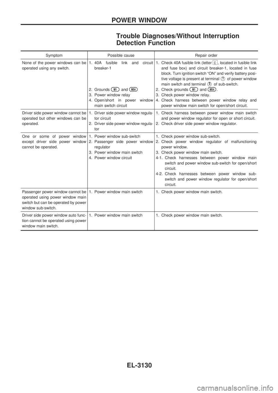
Trouble Diagnoses/Without Interruption
Detection Function
Symptom Possible cause Repair order
None of the power windows can be
operated using any switch.1. 40A fusible link and circuit
breaker-1
2. Grounds
M1andM54
3. Power window relay
4. Open/short in power window
main switch circuit1. Check 40A fusible link (letter
c, located in fusible link
and fuse box) and circuit breaker-1, located in fuse
block. Turn ignition switch ªONº and verify battery posi-
tive voltage is present at terminal
V1of power window
main switch and terminal
V5of sub-switch.
2. Check grounds
M1andM54.
3. Check power window relay.
4. Check harness between power window relay and
power window main switch for open/short circuit.
Driver side power window cannot be
operated but other windows can be
operated.1. Driver side power window regula-
tor circuit
2. Driver side power window regula-
tor1. Check harness between power window main switch
and power window regulator for open or short circuit.
2. Check driver side power window regulator.
One or some of power window
except driver side power window
cannot be operated.1. Power window sub-switch
2. Passenger side power window
regulator
3. Power window main switch
4. Power window circuit1. Check power window sub-switch.
2. Check power window regulator of malfunctioning
power window.
3. Check power window main switch.
4-1. Check harnesses between power window main
switch and power window sub-switch for open/short
circuit.
4-2. Check harnesses between power window sub-
switch and power window regulator for open/short
circuit.
Passenger power window cannot be
operated using power window main
switch but can be operated by power
window sub-switch.1. Power window main switch 1. Check power window main switch.
Driver side power window auto func-
tion cannot be operated using power
window main switch.1. Power window main switch 1. Check power window main switch.
POWER WINDOW
EL-3130
Page 1242 of 1306
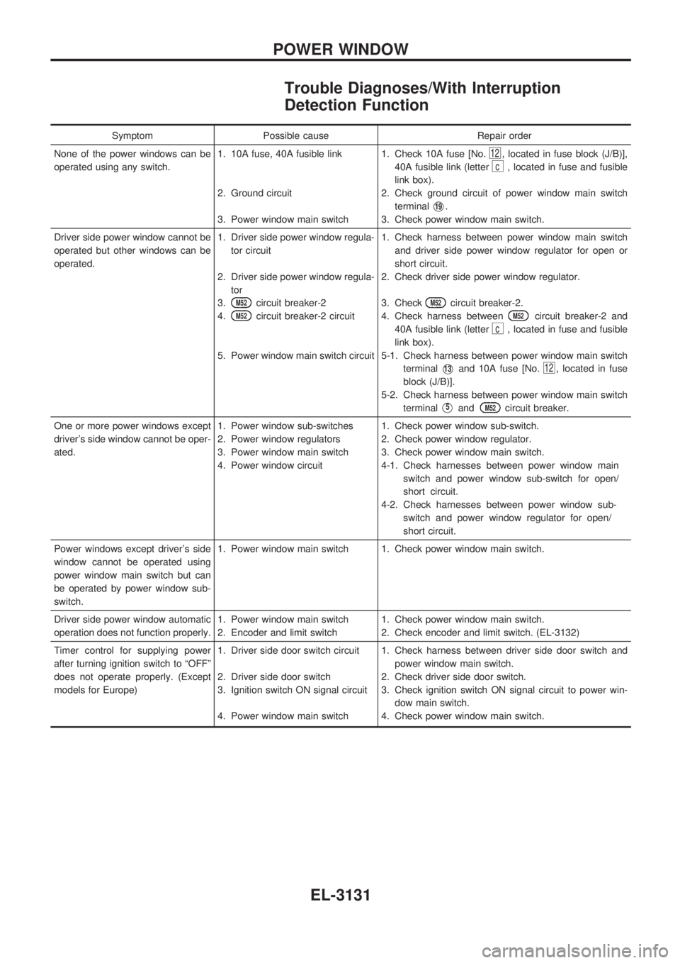
Trouble Diagnoses/With Interruption
Detection Function
Symptom Possible cause Repair order
None of the power windows can be
operated using any switch.1. 10A fuse, 40A fusible link
2. Ground circuit
3. Power window main switch1. Check 10A fuse [No.
12, located in fuse block (J/B)],
40A fusible link (letter
c, located in fuse and fusible
link box).
2. Check ground circuit of power window main switch
terminal
V19.
3. Check power window main switch.
Driver side power window cannot be
operated but other windows can be
operated.1. Driver side power window regula-
tor circuit
2. Driver side power window regula-
tor
3.
M52circuit breaker-2
4.
M52circuit breaker-2 circuit
5. Power window main switch circuit1. Check harness between power window main switch
and driver side power window regulator for open or
short circuit.
2. Check driver side power window regulator.
3. Check
M52circuit breaker-2.
4. Check harness between
M52circuit breaker-2 and
40A fusible link (letter
c, located in fuse and fusible
link box).
5-1. Check harness between power window main switch
terminal
V13and 10A fuse [No.12, located in fuse
block (J/B)].
5-2. Check harness between power window main switch
terminal
V5andM52circuit breaker.
One or more power windows except
driver's side window cannot be oper-
ated.1. Power window sub-switches
2. Power window regulators
3. Power window main switch
4. Power window circuit1. Check power window sub-switch.
2. Check power window regulator.
3. Check power window main switch.
4-1. Check harnesses between power window main
switch and power window sub-switch for open/
short circuit.
4-2. Check harnesses between power window sub-
switch and power window regulator for open/
short circuit.
Power windows except driver's side
window cannot be operated using
power window main switch but can
be operated by power window sub-
switch.1. Power window main switch 1. Check power window main switch.
Driver side power window automatic
operation does not function properly.1. Power window main switch
2. Encoder and limit switch1. Check power window main switch.
2. Check encoder and limit switch. (EL-3132)
Timer control for supplying power
after turning ignition switch to ªOFFº
does not operate properly. (Except
models for Europe)1. Driver side door switch circuit
2. Driver side door switch
3. Ignition switch ON signal circuit
4. Power window main switch1. Check harness between driver side door switch and
power window main switch.
2. Check driver side door switch.
3. Check ignition switch ON signal circuit to power win-
dow main switch.
4. Check power window main switch.
POWER WINDOW
EL-3131
Page 1243 of 1306
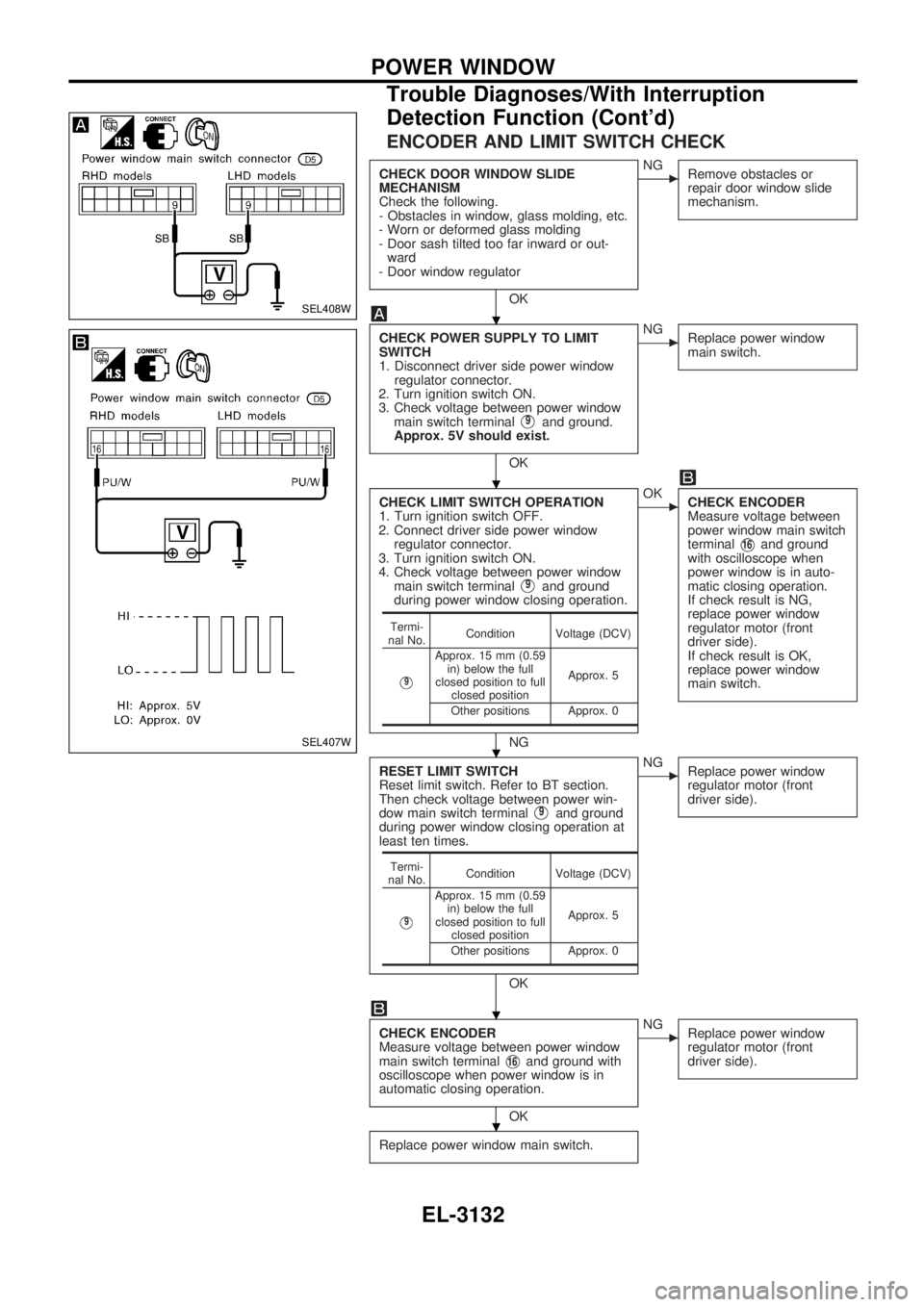
ENCODER AND LIMIT SWITCH CHECK
CHECK DOOR WINDOW SLIDE
MECHANISM
Check the following.
- Obstacles in window, glass molding, etc.
- Worn or deformed glass molding
- Door sash tilted too far inward or out-
ward
- Door window regulator
OK
cNG
Remove obstacles or
repair door window slide
mechanism.
CHECK POWER SUPPLY TO LIMIT
SWITCH
1. Disconnect driver side power window
regulator connector.
2. Turn ignition switch ON.
3. Check voltage between power window
main switch terminal
V9and ground.
Approx. 5V should exist.
OK
cNG
Replace power window
main switch.
CHECK LIMIT SWITCH OPERATION
1. Turn ignition switch OFF.
2. Connect driver side power window
regulator connector.
3. Turn ignition switch ON.
4. Check voltage between power window
main switch terminal
V9and ground
during power window closing operation.
NG
cOK
CHECK ENCODER
Measure voltage between
power window main switch
terminal
V16and ground
with oscilloscope when
power window is in auto-
matic closing operation.
If check result is NG,
replace power window
regulator motor (front
driver side).
If check result is OK,
replace power window
main switch.
RESET LIMIT SWITCH
Reset limit switch. Refer to BT section.
Then check voltage between power win-
dow main switch terminal
V9and ground
during power window closing operation at
least ten times.
OK
cNG
Replace power window
regulator motor (front
driver side).
CHECK ENCODER
Measure voltage between power window
main switch terminal
V16and ground with
oscilloscope when power window is in
automatic closing operation.
OK
cNG
Replace power window
regulator motor (front
driver side).
Replace power window main switch.
Termi-
nal No.Condition Voltage (DCV)
V9
Approx. 15 mm (0.59
in) below the full
closed position to full
closed positionApprox. 5
Other positions Approx. 0
Termi-
nal No.Condition Voltage (DCV)
V9
Approx. 15 mm (0.59
in) below the full
closed position to full
closed positionApprox. 5
Other positions Approx. 0
SEL408W
SEL407W
.
.
.
.
.
POWER WINDOW
Trouble Diagnoses/With Interruption
Detection Function (Cont'd)
EL-3132
Page 1305 of 1306
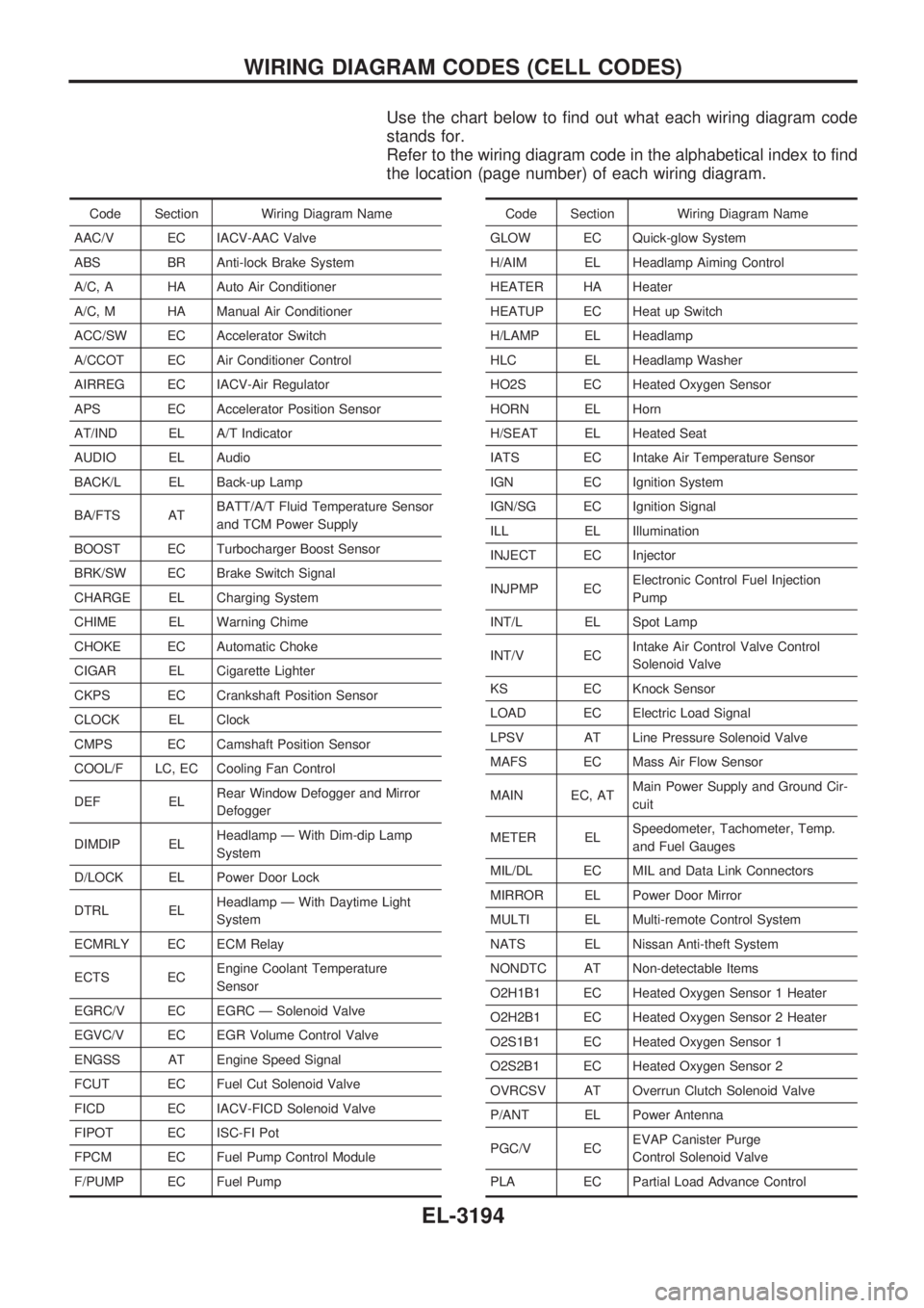
Use the chart below to find out what each wiring diagram code
stands for.
Refer to the wiring diagram code in the alphabetical index to find
the location (page number) of each wiring diagram.
Code Section Wiring Diagram Name
AAC/V EC IACV-AAC Valve
ABS BR Anti-lock Brake System
A/C, A HA Auto Air Conditioner
A/C, M HA Manual Air Conditioner
ACC/SW EC Accelerator Switch
A/CCOT EC Air Conditioner Control
AIRREG EC IACV-Air Regulator
APS EC Accelerator Position Sensor
AT/IND EL A/T Indicator
AUDIO EL Audio
BACK/L EL Back-up Lamp
BA/FTS ATBATT/A/T Fluid Temperature Sensor
and TCM Power Supply
BOOST EC Turbocharger Boost Sensor
BRK/SW EC Brake Switch Signal
CHARGE EL Charging System
CHIME EL Warning Chime
CHOKE EC Automatic Choke
CIGAR EL Cigarette Lighter
CKPS EC Crankshaft Position Sensor
CLOCK EL Clock
CMPS EC Camshaft Position Sensor
COOL/F LC, EC Cooling Fan Control
DEF ELRear Window Defogger and Mirror
Defogger
DIMDIP ELHeadlamp Ð With Dim-dip Lamp
System
D/LOCK EL Power Door Lock
DTRL ELHeadlamp Ð With Daytime Light
System
ECMRLY EC ECM Relay
ECTS ECEngine Coolant Temperature
Sensor
EGRC/V EC EGRC Ð Solenoid Valve
EGVC/V EC EGR Volume Control Valve
ENGSS AT Engine Speed Signal
FCUT EC Fuel Cut Solenoid Valve
FICD EC IACV-FICD Solenoid Valve
FIPOT EC ISC-FI Pot
FPCM EC Fuel Pump Control Module
F/PUMP EC Fuel PumpCode Section Wiring Diagram Name
GLOW EC Quick-glow System
H/AIM EL Headlamp Aiming Control
HEATER HA Heater
HEATUP EC Heat up Switch
H/LAMP EL Headlamp
HLC EL Headlamp Washer
HO2S EC Heated Oxygen Sensor
HORN EL Horn
H/SEAT EL Heated Seat
IATS EC Intake Air Temperature Sensor
IGN EC Ignition System
IGN/SG EC Ignition Signal
ILL EL Illumination
INJECT EC Injector
INJPMP ECElectronic Control Fuel Injection
Pump
INT/L EL Spot Lamp
INT/V ECIntake Air Control Valve Control
Solenoid Valve
KS EC Knock Sensor
LOAD EC Electric Load Signal
LPSV AT Line Pressure Solenoid Valve
MAFS EC Mass Air Flow Sensor
MAIN EC, ATMain Power Supply and Ground Cir-
cuit
METER ELSpeedometer, Tachometer, Temp.
and Fuel Gauges
MIL/DL EC MIL and Data Link Connectors
MIRROR EL Power Door Mirror
MULTI EL Multi-remote Control System
NATS EL Nissan Anti-theft System
NONDTC AT Non-detectable Items
O2H1B1 EC Heated Oxygen Sensor 1 Heater
O2H2B1 EC Heated Oxygen Sensor 2 Heater
O2S1B1 EC Heated Oxygen Sensor 1
O2S2B1 EC Heated Oxygen Sensor 2
OVRCSV AT Overrun Clutch Solenoid Valve
P/ANT EL Power Antenna
PGC/V ECEVAP Canister Purge
Control Solenoid Valve
PLA EC Partial Load Advance Control
WIRING DIAGRAM CODES (CELL CODES)
EL-3194
Page 1306 of 1306
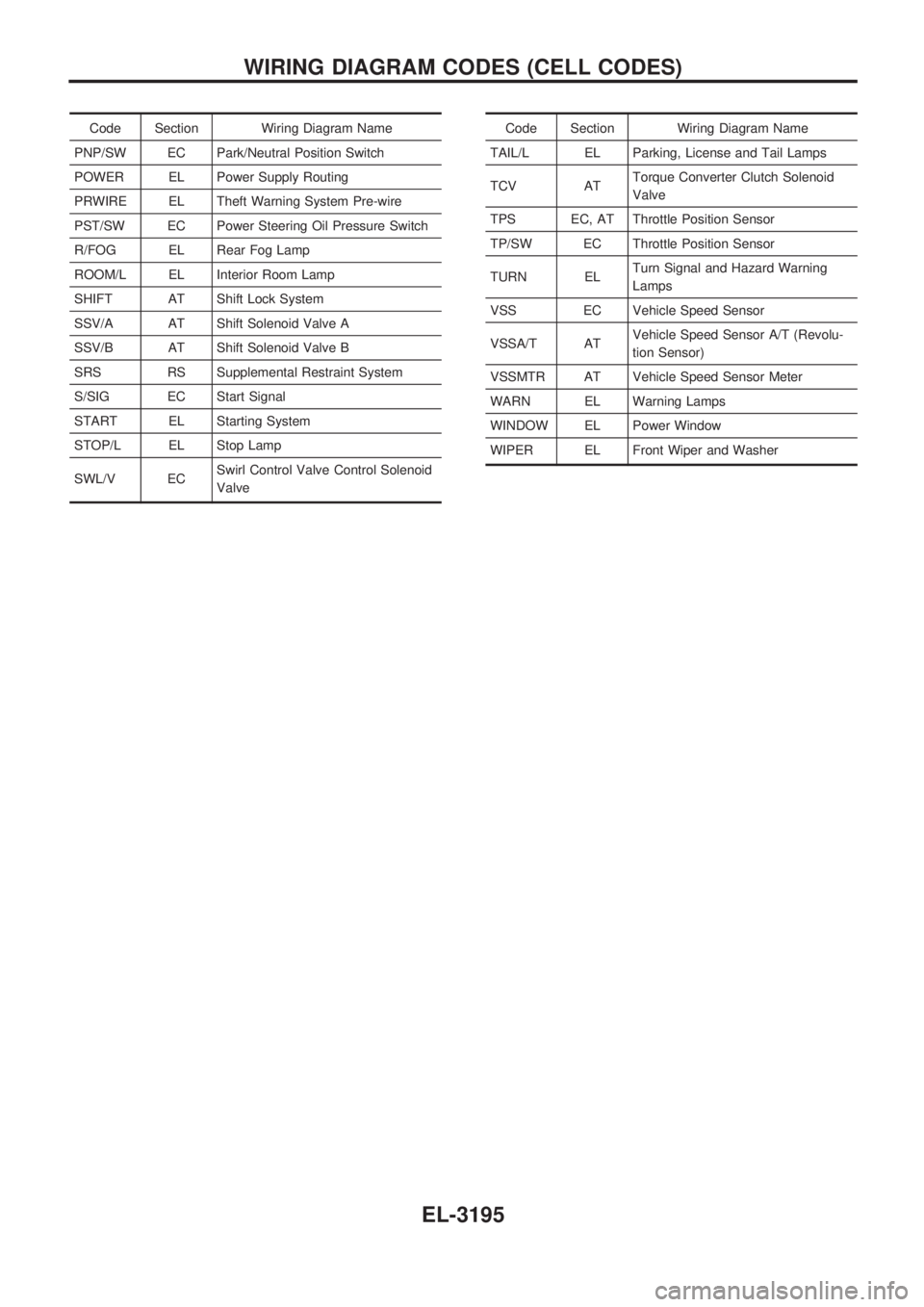
Code Section Wiring Diagram Name
PNP/SW EC Park/Neutral Position Switch
POWER EL Power Supply Routing
PRWIRE EL Theft Warning System Pre-wire
PST/SW EC Power Steering Oil Pressure Switch
R/FOG EL Rear Fog Lamp
ROOM/L EL Interior Room Lamp
SHIFT AT Shift Lock System
SSV/A AT Shift Solenoid Valve A
SSV/B AT Shift Solenoid Valve B
SRS RS Supplemental Restraint System
S/SIG EC Start Signal
START EL Starting System
STOP/L EL Stop Lamp
SWL/V ECSwirl Control Valve Control Solenoid
ValveCode Section Wiring Diagram Name
TAIL/L EL Parking, License and Tail Lamps
TCV ATTorque Converter Clutch Solenoid
Valve
TPS EC, AT Throttle Position Sensor
TP/SW EC Throttle Position Sensor
TURN ELTurn Signal and Hazard Warning
Lamps
VSS EC Vehicle Speed Sensor
VSSA/T ATVehicle Speed Sensor A/T (Revolu-
tion Sensor)
VSSMTR AT Vehicle Speed Sensor Meter
WARN EL Warning Lamps
WINDOW EL Power Window
WIPER EL Front Wiper and Washer
WIRING DIAGRAM CODES (CELL CODES)
EL-3195