Page 770 of 1306
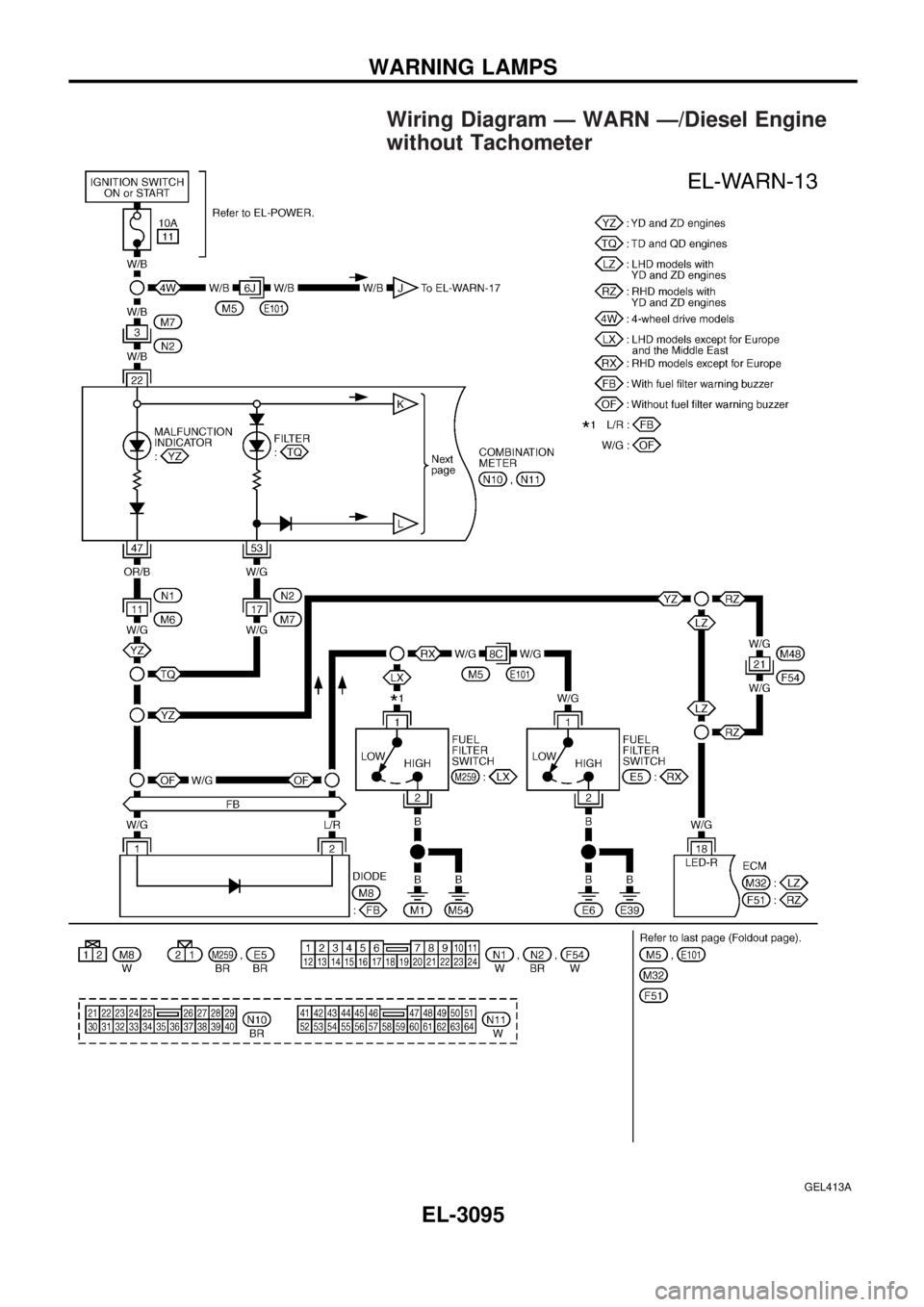
Wiring Diagram Ð WARN Ð/Diesel Engine
without Tachometer
GEL413A
WARNING LAMPS
EL-3095
Page 771 of 1306
GEL414A
WARNING LAMPS
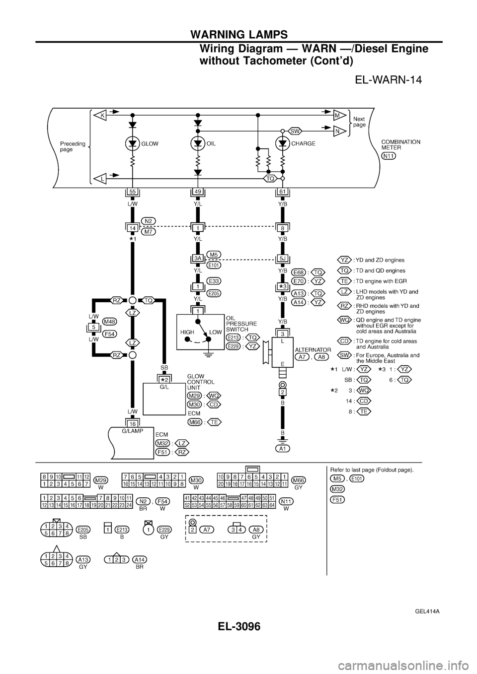
Wiring Diagram Ð WARN Ð/Diesel Engine
without Tachometer (Cont'd)
EL-3096
Page 772 of 1306
GEL415A
WARNING LAMPS
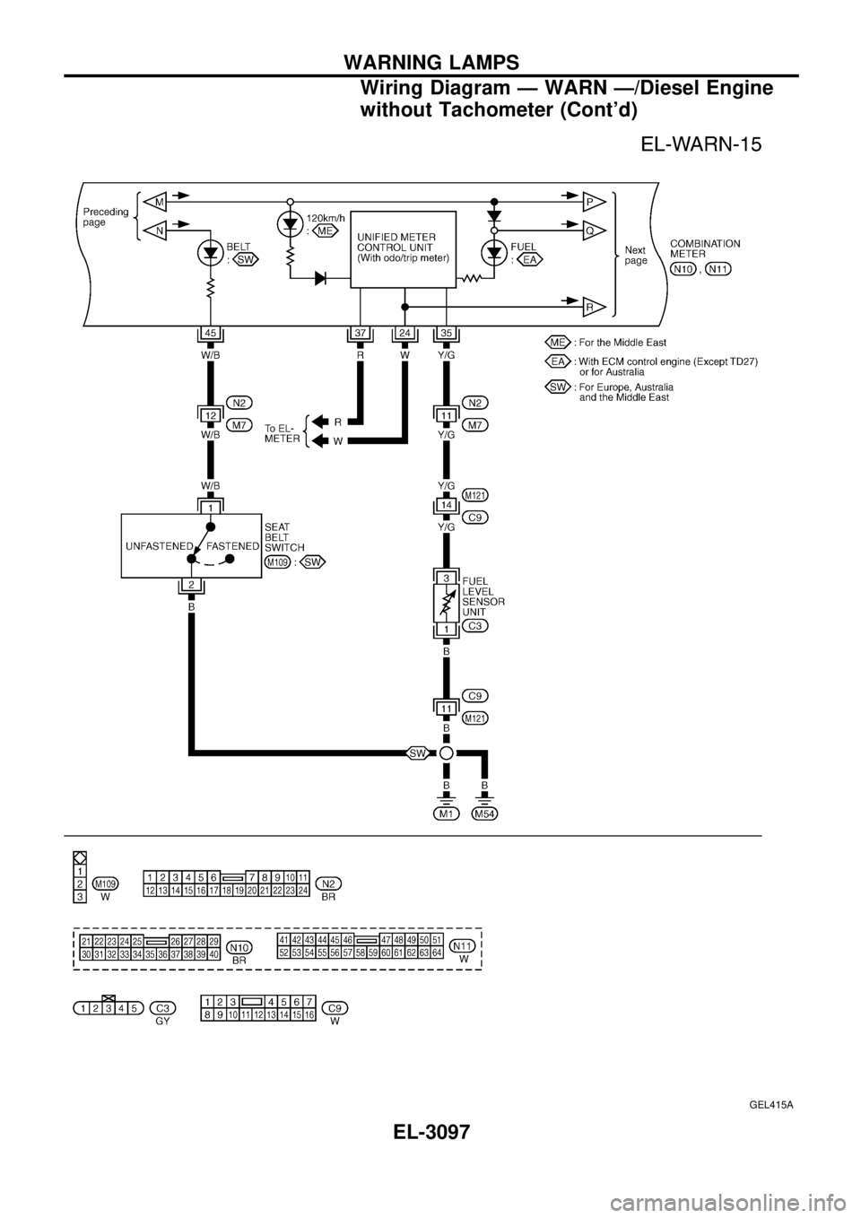
Wiring Diagram Ð WARN Ð/Diesel Engine
without Tachometer (Cont'd)
EL-3097
Page 773 of 1306
GEL416A
WARNING LAMPS
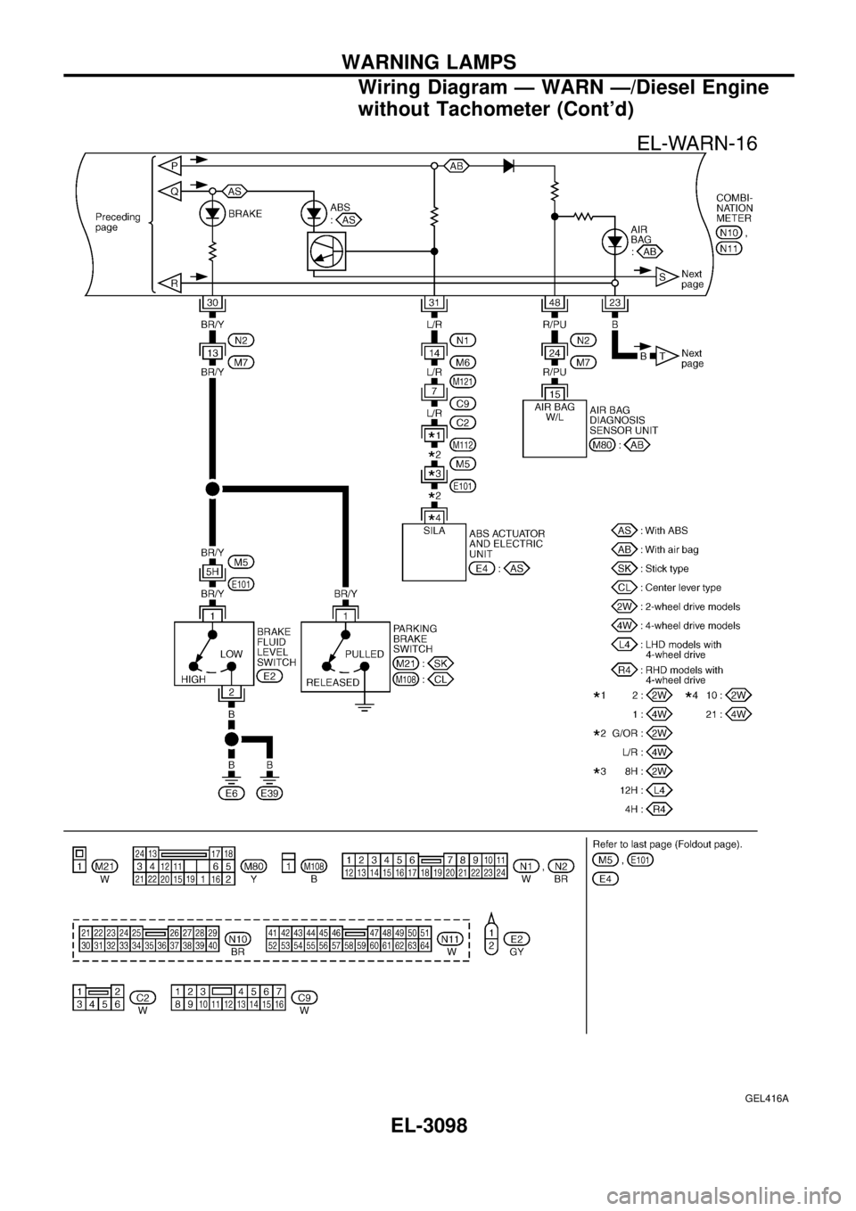
Wiring Diagram Ð WARN Ð/Diesel Engine
without Tachometer (Cont'd)
EL-3098
Page 774 of 1306
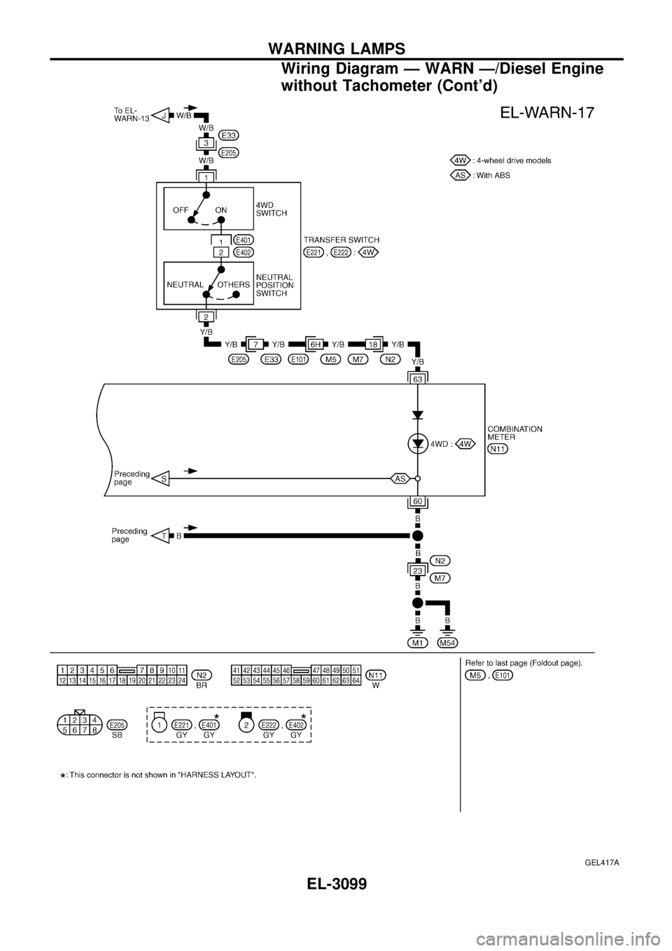
GEL417A
WARNING LAMPS
Wiring Diagram Ð WARN Ð/Diesel Engine
without Tachometer (Cont'd)
EL-3099
Page 776 of 1306
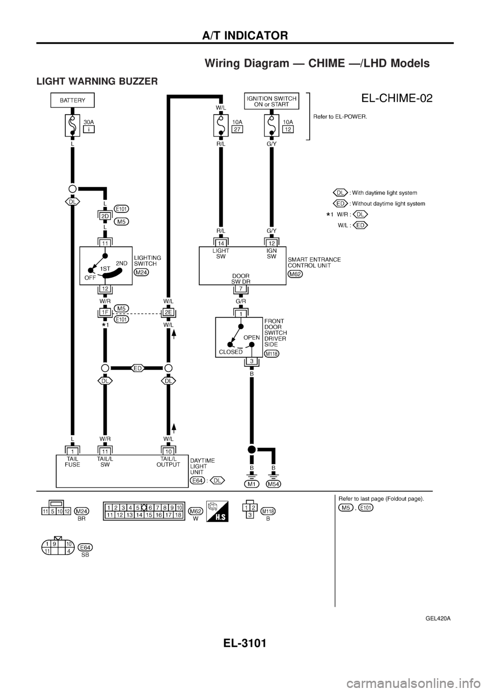
Wiring Diagram Ð CHIME Ð/LHD Models
LIGHT WARNING BUZZER
GEL420A
A/T INDICATOR
EL-3101
Page 777 of 1306
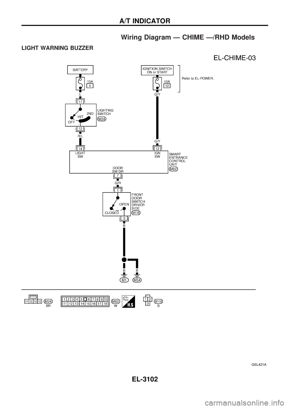
Wiring Diagram Ð CHIME Ð/RHD Models
LIGHT WARNING BUZZER
GEL421A
A/T INDICATOR
EL-3102
Page 810 of 1306
System Description
FUNCTION
Multi-remote control system has the following function.
+Door lock
+Door unlock
+Hazard reminder
LOCK OPERATION
When the LOCK signal is input to multi-remote control unit (the antenna of the system is combined with
multi-remote control unit), ground is supplied
+through multi-remote control unit terminal
V5
+to smart entrance control unit terminalV4.
Then smart entrance control unit supplies power and ground to each door lock actuator.
UNLOCK OPERATION
When the UNLOCK signal is input to multi-remote control unit (the antenna of the system is combined with
multi-remote control unit), ground is supplied
+through multi-remote control unit terminal
V6
+to smart entrance control unit terminalV5.
Then smart entrance control unit supplies power and ground to each door lock actuator.
HAZARD REMINDER
When the doors are locked or unlocked (signal from driver's door unlock sensor) by multi-remote controller,
power is supplied
+through multi-remote control unit terminals
V3andV8
+to the hazard warning lamps
Then hazard warning lamp flash as follows.
+Lock operation: Flash once
+Unlock operation: Flash twice
MULTI-REMOTE CONTROLLER ID CODE ENTRY
A maximum of four remote controllers can be entered. Any attempt to enter a remote controller will erase
all ID codes previously entered. Therefore, be sure to receive all remote controllers from the vehicle owner
when any ID code entry is performed.
To enter ID code entry, the following signals must be input to the multi-remote control unit.
+Ignition switch ON signal
+Battery power supply
+Signal from remote controller
For detailed procedure, refer to ªID Code Entry Procedureº in EL-3139.
MULTI-REMOTE CONTROL SYSTEM
EL-3135