2001 NISSAN PICK-UP fuse diagram
[x] Cancel search: fuse diagramPage 991 of 1306
VA
NoteNote
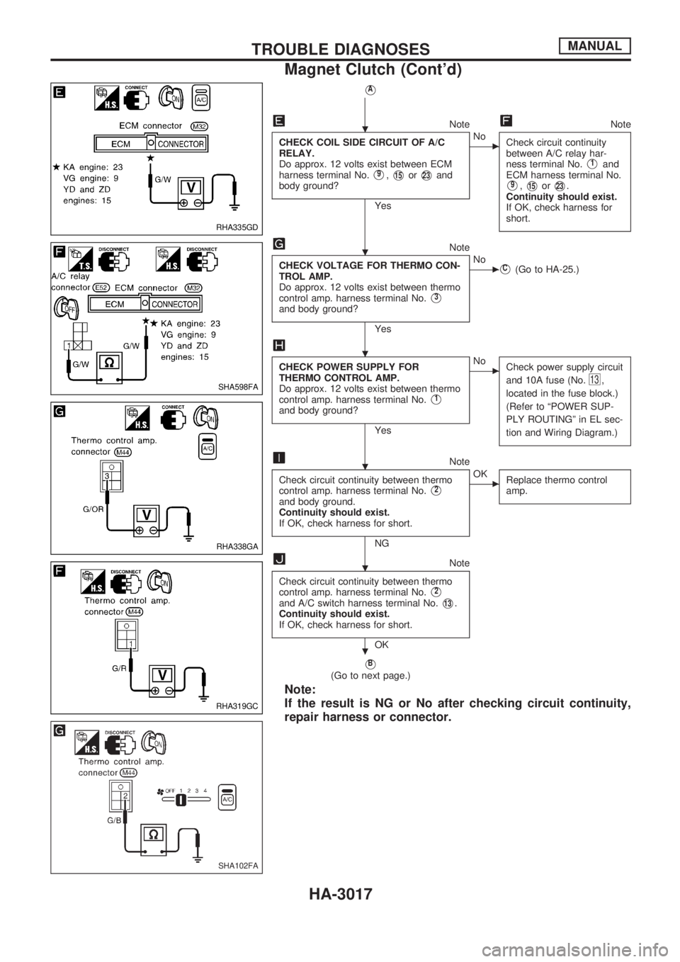
CHECK COIL SIDE CIRCUIT OF A/C
RELAY.
Do approx. 12 volts exist between ECM
harness terminal No.
V9,V15orV23and
body ground?
Yes
cNo
Check circuit continuity
between A/C relay har-
ness terminal No.
V1and
ECM harness terminal No.
V9,V15orV23.
Continuity should exist.
If OK, check harness for
short.
Note
CHECK VOLTAGE FOR THERMO CON-
TROL AMP.
Do approx. 12 volts exist between thermo
control amp. harness terminal No.
V3
and body ground?
Yes
cNoVC(Go to HA-25.)
CHECK POWER SUPPLY FOR
THERMO CONTROL AMP.
Do approx. 12 volts exist between thermo
control amp. harness terminal No.
V1
and body ground?
Yes
cNo
Check power supply circuit
and 10A fuse (No.
13,
located in the fuse block.)
(Refer to ªPOWER SUP-
PLY ROUTINGº in EL sec-
tion and Wiring Diagram.)
Note
Check circuit continuity between thermo
control amp. harness terminal No.
V2
and body ground.
Continuity should exist.
If OK, check harness for short.
NG
cOK
Replace thermo control
amp.
Note
Check circuit continuity between thermo
control amp. harness terminal No.
V2
and A/C switch harness terminal No.V13.
Continuity should exist.
If OK, check harness for short.
OK
VB
(Go to next page.)
Note:
If the result is NG or No after checking circuit continuity,
repair harness or connector.
RHA335GD
SHA598FA
RHA338GA
RHA319GC
SHA102FA
.
.
.
.
.
.
TROUBLE DIAGNOSESMANUAL
Magnet Clutch (Cont'd)
HA-3017
Page 1001 of 1306
DIAGNOSTIC PROCEDURE
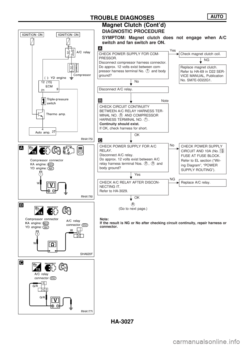
SYMPTOM: Magnet clutch does not engage when A/C
switch and fan switch are ON.
CHECK POWER SUPPLY FOR COM-
PRESSOR.
Disconnect compressor harness connector.
Do approx. 12 volts exist between com-
pressor harness terminal No.
V1and body
ground?
No
cYes
Check magnet clutch coil.
NG
Replace magnet clutch.
Refer to HA-69 in D22 SER-
VICE MANUAL, Publication
No. SM7E-0D22G1.
Disconnect A/C relay.
Note
CHECK CIRCUIT CONTINUITY
BETWEEN A/C RELAY HARNESS TER-
MINAL NO.
V5AND COMPRESSOR
HARNESS TERMINAL NO.
V1.
Continuity should exist.
If OK, check harness for short.
OK
CHECK POWER SUPPLY FOR A/C
RELAY.
Disconnect A/C relay.
Do approx. 12 volts exist between A/C
relay harness terminal Nos.
V2,V3and
body ground?
Yes
cNo
CHECK POWER SUPPLY
CIRCUIT AND 10A (No.
13)
FUSE AT FUSE BLOCK.
Refer to EL section (ªWir-
ing Diagramº, ªPOWER
SUPPLY ROUTINGº).
CHECK A/C RELAY AFTER DISCON-
NECTING IT.
Refer to HA-3029.
OK
cNG
Replace A/C relay.
VA
(Go to next page.)
Note:
If the result is NG or No after checking circuit continuity, repair harness or
connector.
RHA175I
RHA176I
SHA620F
RHA177I
.
.
.
.
.
.
TROUBLE DIAGNOSESAUTO
Magnet Clutch (Cont'd)
HA-3027
Page 1002 of 1306
VA
NoteNote
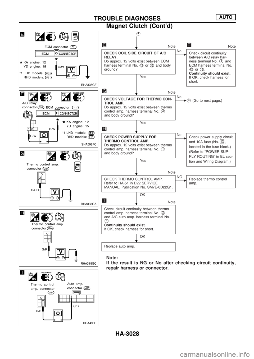
CHECK COIL SIDE CIRCUIT OF A/C
RELAY.
Do approx. 12 volts exist between ECM
harness terminal No.
V12orV15and body
ground?
Yes
cNo
Check circuit continuity
between A/C relay har-
ness terminal No.
V1and
ECM harness terminal No.
V12orV15.
Continuity should exist.
If OK, check harness for
short.
Note
CHECK VOLTAGE FOR THERMO CON-
TROL AMP.
Do approx. 12 volts exist between thermo
control amp. harness terminal No.
V3
and body ground?
Yes
cNoVB(Go to next page.)
CHECK POWER SUPPLY FOR
THERMO CONTROL AMP.
Do approx. 12 volts exist between thermo
control amp. harness terminal No.
V1
and body ground?
Yes
cNo
Check power supply circuit
and 10A fuse (No.
13,
located in the fuse block.)
(Refer to ªPOWER SUP-
PLY ROUTINGº in EL sec-
tion and Wiring Diagram.)
Note
CHECK THERMO CONTROL AMP.
Refer to HA-51 in D22 SERVICE
MANUAL, Publication No. SM7E-0D22G1.
OK
cNG
Replace thermo control
amp.
Note
Check circuit continuity between thermo
control amp. harness terminal No.
V2
and A/C auto amp. harness terminal No.
V4.
Continuity should exist.
If OK, check harness for short.
OK
Replace auto amp.
Note:
If the result is NG or No after checking circuit continuity,
repair harness or connector.
RHA335GF
SHA598FC
RHA338GA
RHA319GC
RHA498H
.
.
.
.
.
.
TROUBLE DIAGNOSESAUTO
Magnet Clutch (Cont'd)
HA-3028
Page 1063 of 1306
EGR volume control valve .......... EC-3605, 3606
EVAP canister purge volume control
solenoid valve ................................... EC-3283
EVAP canister ....................................... EC-3029
Electrical ignition system ...................... EC-3026
Electronic fuel injection
pump ........ EC-3419, 3420, 3508, 3509, 3542,
3543, 3549, 3550, 3556, 3557,
3563, 3564, 3570, 3571, 3573,
3574, 3614, 3615
Engine control circuit
diagram ......................... EC-3020, 3408, 3409
Engine control component parts
location .............................................. EC-3018
Engine control module (ECM) .............. EC-3308
Engine control system diagram and
chart .............................. EC-3021, 3409, 3410
Engine coolant temperature sensor
(ECTS) .......................... EC-3165, 3480, 3481
Engine fail-safe system ......................... EC-3101
Engine oil filter replacement ................. MA-3013
Engine oil replacement ......................... MA-3012
Engine outer component parts ............. EM-3008
Engine removal ..................................... EM-3063
Engine serial number ............................. GI-3006
Evaporative emission (EVAP)
system ............................................... EC-3029
Exhaust system ..................................... FE-3005
Exterior .................................................. BT-3006
F
F/PUMP - Wiring diagram ..................... EC-3380
FICD - Wiring diagram .......................... EC-3390
FUEL - Wiring diagram ............... EC-3239, 3246
Fast idle cam (FIC) ............................... EC-3035
Fluids .................................................... MA-3008
Flywheel runout .................................... EM-3080
Fog lamp, rear ....................................... EL-3045
Freeze frame data ................................ EC-3050
Front bumper ......................................... BT-3002
Front case (Transfer) ............................. TF-3003
Front combination lamp removal and
installation .......................................... BT-3002
Front drive shaft (Transfer) ................... TF-3004
Front passenger air bag ............. RS-3003, 3009
Fuel cut control (at no load & high
engine speed) ............... EC-3028, 3413, 3414
Fuel filter replacement .......................... MA-3018
Fuel filter ............................................... EC-3033
Fuel injection system ................. EC-3237, 3244,
3411, 3412
Fuel injector .......................................... EC-3369
Fuel line inspection ............................... MA-3019
Fuel pressure check ............................. EC-3033
Fuel pressure regulator ......................... EC-3034
Fuel pressure release ........................... EC-3033
Fuel pump relay .................................... EC-3378
Fuel pump ............................................. EC-3378Fuel system ........................................... FE-3003
Fuel tank vacuum relief valve ............... EC-3030
Fuse block ............................................. EL-3199
G
Gauges .................................................. EL-3056
Generic scan tool (GST) ....................... EC-3080
Glow plug .................................... EC-3621, 3622
Glow relay ................................... EC-3621, 3622
Grease .................................................. MA-3008
H
H/AIM - Wiring diagram ......................... EL-3037
H/LAMP - Wiring diagram ..................... EL-3023
HEAT UP - Wiring diagram ........ EC-3639, 3640
HEATER - Wiring diagram .................... HA-3004
HLC - Wiring diagram ............................ EL-3108
HORN - Wiring diagram ........................ EL-3109
HSEAT - Wiring diagram ....................... EL-3118
Harness layout ....................................... EL-3166
Hazard warning lamp ............................ EL-3047
Headlamp aiming control ....................... EL-3037
Headlamp removal and installation ....... BT-3002
Headlamp washer .................................. EL-3108
Headlamp .............................................. EL-3023
Heat up switch ............................ EC-3638, 3639
Heated oxygen sensor (HO2S)
(front) ........ EC-3202, 3213, 3196, 3310, 3317
Heated oxygen sensor (HO2S) heater
(front) ................................................. EC-3133
Heated oxygen sensor (HO2S) heater
(rear) .................................................. EC-3138
Heated oxygen sensor
(rear) ................... EC-3220, 3227, 3324, 3334
Heated seat ........................................... EL-3118
Hood ...................................................... BT-3002
Horn ....................................................... EL-3109
How to erase DTC for OBD
system ........................... EC-3060, 3428, 3429
I
IACV-AAC valve .................................... EC-3295
IACV-FICD solenoid valve .................... EC-3389
IATS - Wiring diagram ...... EC-3162, 3505, 3506
ILL - Wiring diagram .............................. EL-3050
INJECT - Wiring diagram ...................... EC-3370
INT/L - Wiring diagram .......................... EL-3055
Idle air control (IAC) system ................. EC-3295
Idle air control valve (IACV) .................. EC-3295
Idle mixture ratio ................................... EC-3035
Idle speed ......................... EC-3035, 3444, 3445
Ignition control system .......................... EC-3361
Ignition timing ........................................ EC-3035
Illumination ............................................. EL-3050
ALPHABETICAL INDEX
IDX-3003
Page 1262 of 1306
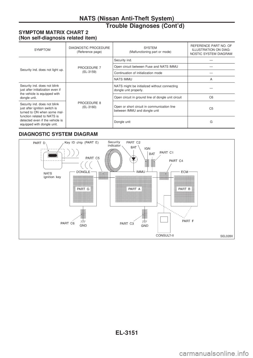
SYMPTOM MATRIX CHART 2
(Non self-diagnosis related item)
SYMPTOMDIAGNOSTIC PROCEDURE
(Reference page)SYSTEM
(Malfunctioning part or mode)REFERENCE PART NO. OF
ILLUSTRATION ON DIAG-
NOSTIC SYSTEM DIAGRAM
Security ind. does not light up.PROCEDURE 7
(EL-3159)Security ind. Ð
Open circuit between Fuse and NATS IMMU Ð
Continuation of initialization mode Ð
NATS IMMU A
Security ind. does not blink
just after initialization even if
the vehicle is equipped with
dongle unit.
PROCEDURE 8
(EL-3160)NATS might be initialized without connecting
dongle unit properly.Ð
Open circuit in ground line of dongle unit circuit C6
Security ind. does not blink
just after ignition switch is
turned to ON when some mal-
function related to NATS is
detected even if the vehicle is
equipped with dongle unit.Open or short circuit in communication line
between IMMU and dongle unitC5
Dongle unit G
DIAGNOSTIC SYSTEM DIAGRAM
SEL028X
NATS (Nissan Anti-Theft System)
Trouble Diagnoses (Cont'd)
EL-3151