Page 502 of 1306
7 CHECK ECM POWER SUPPLY CIRCUIT-III
1. Disconnect ECM relay.
SEC950C
2. Check voltage between relay terminals 2, 7 and ground with CONSULT-II or tester.
SEC241D
OK or NG
OKcGO TO 9.
NGcGO TO 8.
8 DETECT MALFUNCTIONING PART
Check the following.
+20A fuse
+Harness for open or short between ECM relay and fuse
cRepair open circuit or short to ground or short to power in harness or connectors.
9 CHECK OUTPUT SIGNAL CIRCUIT FOR OPEN AND SHORT
1. Disconnect ECM harness connector.
2. Check harness continuity between ECM terminal 4 and ECM relay terminal 1. Refer to Wiring Diagram.
Continuity should exist.
3. Also check harness for short to ground and short to power.
OK or NG
OKcGO TO 11.
NGcGO TO 10.
TROUBLE DIAGNOSIS FOR POWER SUPPLYYD25DDTi
Main Power Supply and Ground Circuit
(Cont'd)
EC-3477
Page 621 of 1306
Diagnostic Procedure
1 CHECK ECM POWER SUPPLY CIRCUIT
1. Turn ignition switch ªOFFº.
2. Disconnect ECM relay.
SEC950C
3. Check voltage between ECM terminals 2, 7 and ground with CONSULT-II or tester.
SEC241D
OK or NG
OKcGO TO 3.
NGcGO TO 2.
2 DETECT MALFUNCTIONING PART
Check the following.
+20A fuse
+Harness for open and short between ECM relay and battery
cRepair open circuit or short to ground or short to power in harness or connectors.
3 CHECK ECM INPUT SIGNAL CIRCUIT FOR OPEN AND SHORT
1. Turn ignition switch ªOFFº.
2. Disconnect ECM harness connector.
3. Check harness continuity between ECM terminals 56, 61 and ECM relay terminal 6. Refer to Wiring Diagram.
Continuity should exist.
4. Also check harness for short to ground and short to power.
OK or NG
OKcGO TO 5.
NGcGO TO 4.
DTC 0902 ECM RLYYD25DDTi
EC-3596
Page 636 of 1306

5 DETECT MALFUNCTIONING PART
Check the following.
+10A fuse
+Harness for open or short between ECM relay and battery
cRepair open circuit or short to ground or short to power in harness or connectors.
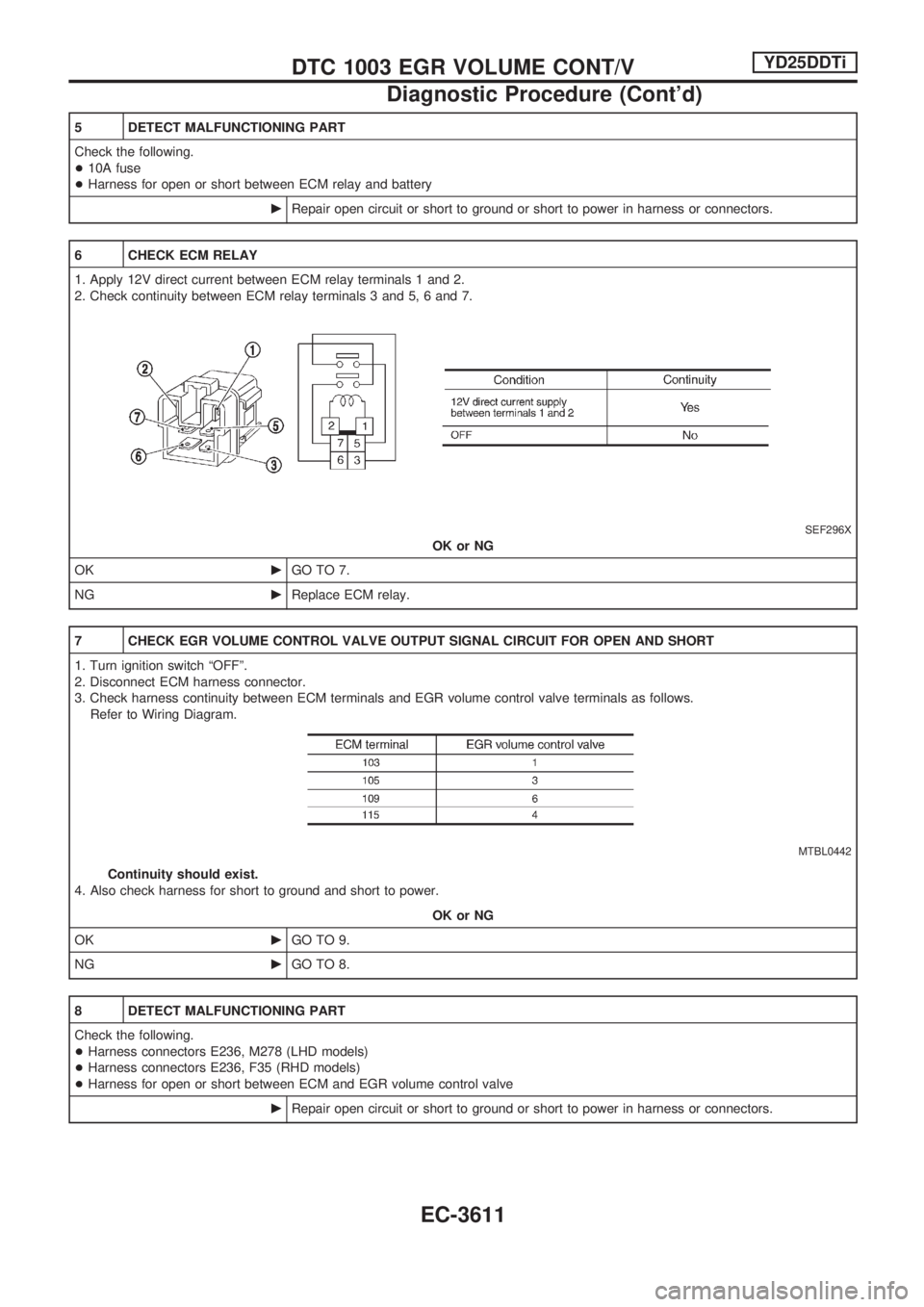
6 CHECK ECM RELAY
1. Apply 12V direct current between ECM relay terminals 1 and 2.
2. Check continuity between ECM relay terminals 3 and 5, 6 and 7.
SEF296X
OK or NG
OKcGO TO 7.
NGcReplace ECM relay.
7 CHECK EGR VOLUME CONTROL VALVE OUTPUT SIGNAL CIRCUIT FOR OPEN AND SHORT
1. Turn ignition switch ªOFFº.
2. Disconnect ECM harness connector.
3. Check harness continuity between ECM terminals and EGR volume control valve terminals as follows.
Refer to Wiring Diagram.
MTBL0442
Continuity should exist.
4. Also check harness for short to ground and short to power.
OK or NG
OKcGO TO 9.
NGcGO TO 8.
8 DETECT MALFUNCTIONING PART
Check the following.
+Harness connectors E236, M278 (LHD models)
+Harness connectors E236, F35 (RHD models)
+Harness for open or short between ECM and EGR volume control valve
cRepair open circuit or short to ground or short to power in harness or connectors.
DTC 1003 EGR VOLUME CONT/VYD25DDTi
Diagnostic Procedure (Cont'd)
EC-3611
Page 666 of 1306

4 CHECK OVERALL FUNCTION-II
Check the indicator when turning ªONº and ªOFFº the heat up switch.
MTBL1314
OK or NG
OKcINSPECTION END
NGcGO TO 10.
5 CHECK HEAT UP SWITCH POWER SUPPLY CIRCUIT
1. Turn heat up switch ªOFFº.
2. Turn ignition switch ªOFFº.
3. Disconnect heat up switch harness connector.
4. Turn ignition switch ªONº.
5. Check voltage between heat up switch terminal 6 and ground with CONSULT-II or tester.
SEF304Z
OK or NG
OKcGO TO 7.
NGcGO TO 6.
6 DETECT MALFUNCTIONING PART
Check the following.
+Harness connectors N1, M6
+10A fuse
+Harness for open or short between heat up switch and fuse
cRepair open circuit or short to ground or short to power in harness or connectors.
7 CHECK HEAT UP SWITCH INPUT SIGNAL CIRCUIT FOR OPEN OR SHORT
1. Turn ignition switch ªOFFº.
2. Disconnect ECM harness connector.
3. Check harness continuity between ECM terminal 59 and heat up switch terminal 5. Refer to Wiring Diagram.
Continuity should exist.
4. Also check harness for short to ground and short to power.
OK or NG
OKcGO TO 9.
NGcGO TO 8.
HEAT UP SWITCHYD25DDTi
Diagnostic Procedure (Cont'd)
EC-3641
Page 826 of 1306
SYMPTOM MATRIX CHART 2
(Non self-diagnosis related item)
SYMPTOMDIAGNOSTIC PROCEDURE
(Reference page)SYSTEM
(Malfunctioning part or mode)REFERENCE PART NO. OF
ILLUSTRATION ON DIAG-
NOSTIC SYSTEM DIAGRAM
Security ind. does not light up.PROCEDURE 7
(EL-3159)Security ind. Ð
Open circuit between Fuse and NATS IMMU Ð
Continuation of initialization mode Ð
NATS IMMU A
Security ind. does not blink
just after initialization even if
the vehicle is equipped with
dongle unit.
PROCEDURE 8
(EL-3160)NATS might be initialized without connecting
dongle unit properly.Ð
Open circuit in ground line of dongle unit circuit C6
Security ind. does not blink
just after ignition switch is
turned to ON when some mal-
function related to NATS is
detected even if the vehicle is
equipped with dongle unit.Open or short circuit in communication line
between IMMU and dongle unitC5
Dongle unit G
DIAGNOSTIC SYSTEM DIAGRAM
SEL028X
NATS (Nissan Anti-Theft System)
Trouble Diagnoses (Cont'd)
EL-3151
Page 986 of 1306

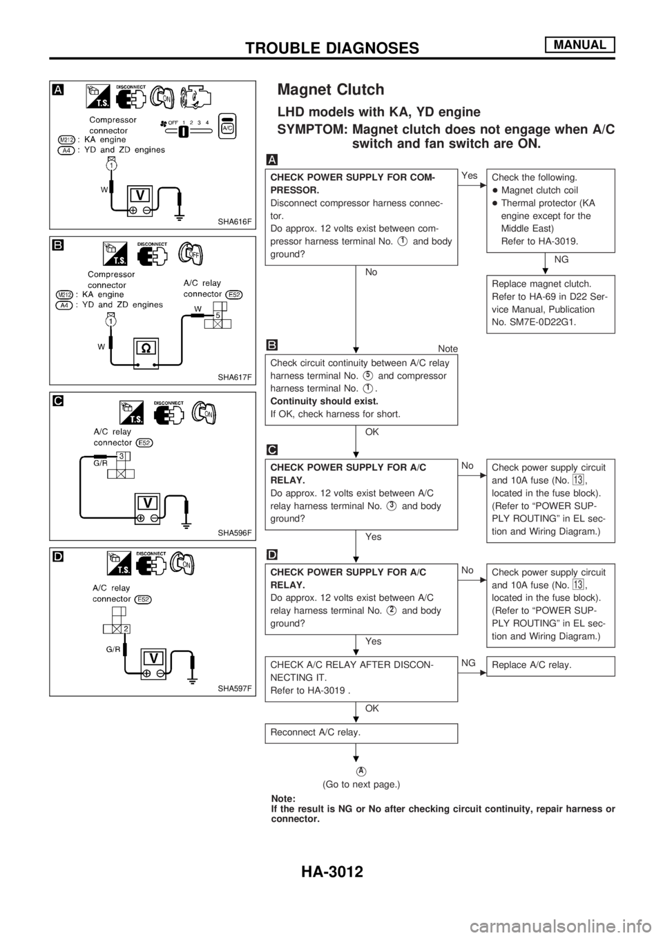
Magnet Clutch
LHD models with KA, YD engine
SYMPTOM: Magnet clutch does not engage when A/C
switch and fan switch are ON.
CHECK POWER SUPPLY FOR COM-
PRESSOR.
Disconnect compressor harness connec-
tor.
Do approx. 12 volts exist between com-
pressor harness terminal No.
V1and body
ground?
No
cYes
Check the following.
+Magnet clutch coil
+Thermal protector (KA
engine except for the
Middle East)
Refer to HA-3019.
NG
Replace magnet clutch.
Refer to HA-69 in D22 Ser-
vice Manual, Publication
No. SM7E-0D22G1.
Note
Check circuit continuity between A/C relay
harness terminal No.
V5and compressor
harness terminal No.
V1.
Continuity should exist.
If OK, check harness for short.
OK
CHECK POWER SUPPLY FOR A/C
RELAY.
Do approx. 12 volts exist between A/C
relay harness terminal No.
V3and body
ground?
Yes
cNo
Check power supply circuit
and 10A fuse (No.
13,
located in the fuse block).
(Refer to ªPOWER SUP-
PLY ROUTINGº in EL sec-
tion and Wiring Diagram.)
CHECK POWER SUPPLY FOR A/C
RELAY.
Do approx. 12 volts exist between A/C
relay harness terminal No.
V2and body
ground?
Yes
cNo
Check power supply circuit
and 10A fuse (No.
13,
located in the fuse block).
(Refer to ªPOWER SUP-
PLY ROUTINGº in EL sec-
tion and Wiring Diagram.)
CHECK A/C RELAY AFTER DISCON-
NECTING IT.
Refer to HA-3019 .
OK
cNG
Replace A/C relay.
Reconnect A/C relay.
VA
(Go to next page.)
Note:
If the result is NG or No after checking circuit continuity, repair harness or
connector.
SHA616F
SHA617F
SHA596F
SHA597F
.
.
.
.
.
.
.
TROUBLE DIAGNOSESMANUAL
HA-3012
Page 987 of 1306

VA
NoteNote
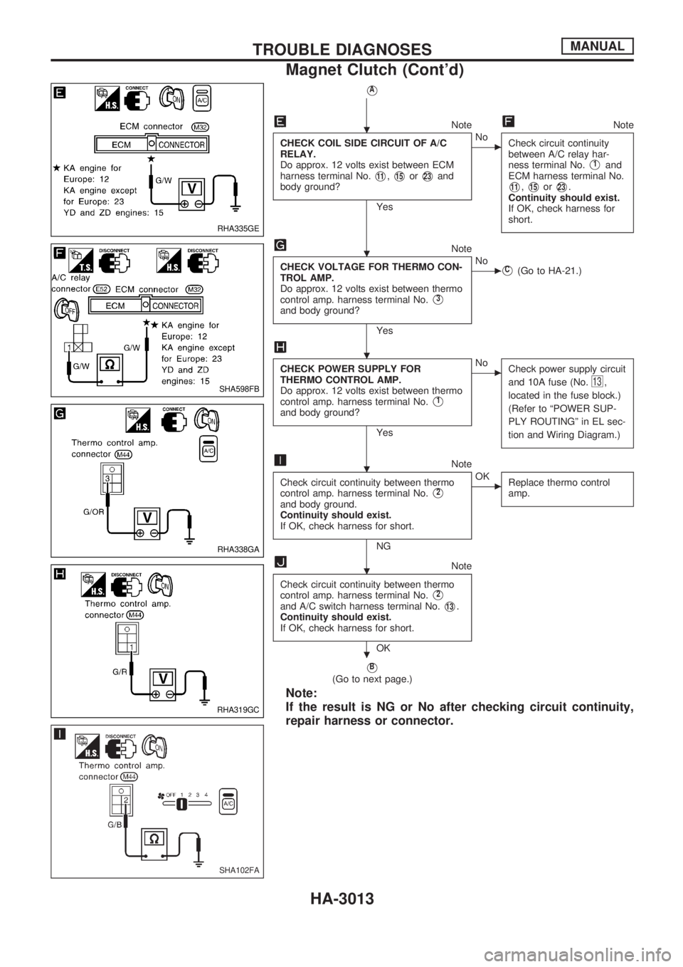
CHECK COIL SIDE CIRCUIT OF A/C
RELAY.
Do approx. 12 volts exist between ECM
harness terminal No.
V11,V15orV23and
body ground?
Yes
cNo
Check circuit continuity
between A/C relay har-
ness terminal No.
V1and
ECM harness terminal No.
V11,V15orV23.
Continuity should exist.
If OK, check harness for
short.
Note
CHECK VOLTAGE FOR THERMO CON-
TROL AMP.
Do approx. 12 volts exist between thermo
control amp. harness terminal No.
V3
and body ground?
Yes
cNoVC(Go to HA-21.)
CHECK POWER SUPPLY FOR
THERMO CONTROL AMP.
Do approx. 12 volts exist between thermo
control amp. harness terminal No.
V1
and body ground?
Yes
cNo
Check power supply circuit
and 10A fuse (No.
13,
located in the fuse block.)
(Refer to ªPOWER SUP-
PLY ROUTINGº in EL sec-
tion and Wiring Diagram.)
Note
Check circuit continuity between thermo
control amp. harness terminal No.
V2
and body ground.
Continuity should exist.
If OK, check harness for short.
NG
cOK
Replace thermo control
amp.
Note
Check circuit continuity between thermo
control amp. harness terminal No.
V2
and A/C switch harness terminal No.V13.
Continuity should exist.
If OK, check harness for short.
OK
VB
(Go to next page.)
Note:
If the result is NG or No after checking circuit continuity,
repair harness or connector.
RHA335GE
SHA598FB
RHA338GA
RHA319GC
SHA102FA
.
.
.
.
.
.
TROUBLE DIAGNOSESMANUAL
Magnet Clutch (Cont'd)
HA-3013
Page 990 of 1306

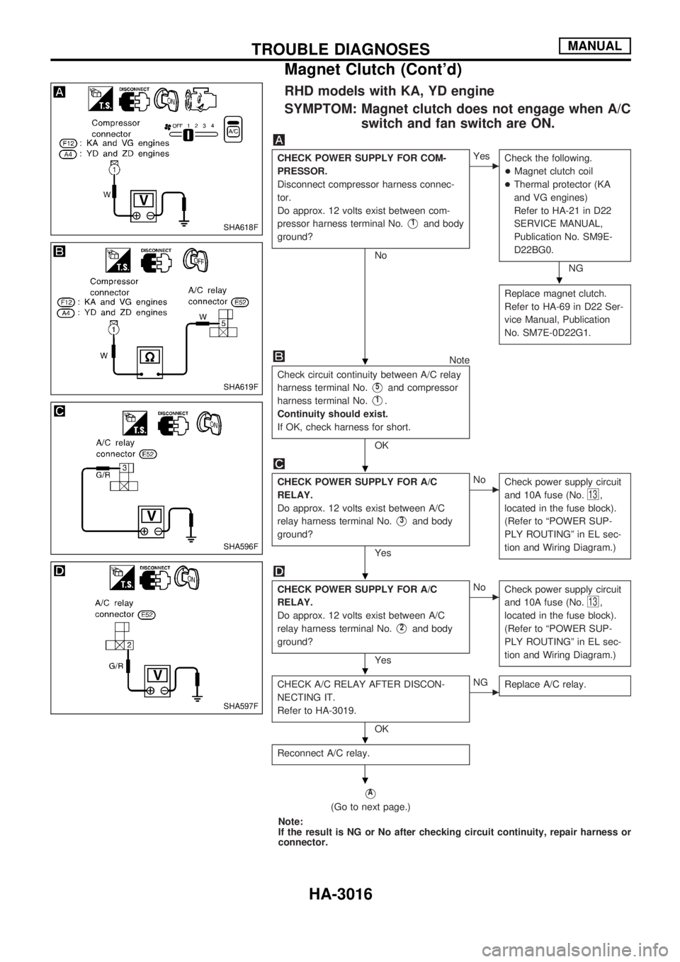
RHD models with KA, YD engine
SYMPTOM: Magnet clutch does not engage when A/C
switch and fan switch are ON.
CHECK POWER SUPPLY FOR COM-
PRESSOR.
Disconnect compressor harness connec-
tor.
Do approx. 12 volts exist between com-
pressor harness terminal No.
V1and body
ground?
No
cYes
Check the following.
+Magnet clutch coil
+Thermal protector (KA
and VG engines)
Refer to HA-21 in D22
SERVICE MANUAL,
Publication No. SM9E-
D22BG0.
NG
Replace magnet clutch.
Refer to HA-69 in D22 Ser-
vice Manual, Publication
No. SM7E-0D22G1.
Note
Check circuit continuity between A/C relay
harness terminal No.
V5and compressor
harness terminal No.
V1.
Continuity should exist.
If OK, check harness for short.
OK
CHECK POWER SUPPLY FOR A/C
RELAY.
Do approx. 12 volts exist between A/C
relay harness terminal No.
V3and body
ground?
Yes
cNo
Check power supply circuit
and 10A fuse (No.
13,
located in the fuse block).
(Refer to ªPOWER SUP-
PLY ROUTINGº in EL sec-
tion and Wiring Diagram.)
CHECK POWER SUPPLY FOR A/C
RELAY.
Do approx. 12 volts exist between A/C
relay harness terminal No.
V2and body
ground?
Yes
cNo
Check power supply circuit
and 10A fuse (No.
13,
located in the fuse block).
(Refer to ªPOWER SUP-
PLY ROUTINGº in EL sec-
tion and Wiring Diagram.)
CHECK A/C RELAY AFTER DISCON-
NECTING IT.
Refer to HA-3019.
OK
cNG
Replace A/C relay.
Reconnect A/C relay.
VA
(Go to next page.)
Note:
If the result is NG or No after checking circuit continuity, repair harness or
connector.
SHA618F
SHA619F
SHA596F
SHA597F
.
.
.
.
.
.
.
TROUBLE DIAGNOSESMANUAL
Magnet Clutch (Cont'd)
HA-3016