2001 NISSAN PICK-UP clock
[x] Cancel search: clockPage 869 of 1306
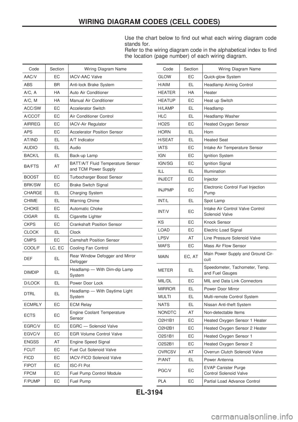
Use the chart below to find out what each wiring diagram code
stands for.
Refer to the wiring diagram code in the alphabetical index to find
the location (page number) of each wiring diagram.
Code Section Wiring Diagram Name
AAC/V EC IACV-AAC Valve
ABS BR Anti-lock Brake System
A/C, A HA Auto Air Conditioner
A/C, M HA Manual Air Conditioner
ACC/SW EC Accelerator Switch
A/CCOT EC Air Conditioner Control
AIRREG EC IACV-Air Regulator
APS EC Accelerator Position Sensor
AT/IND EL A/T Indicator
AUDIO EL Audio
BACK/L EL Back-up Lamp
BA/FTS ATBATT/A/T Fluid Temperature Sensor
and TCM Power Supply
BOOST EC Turbocharger Boost Sensor
BRK/SW EC Brake Switch Signal
CHARGE EL Charging System
CHIME EL Warning Chime
CHOKE EC Automatic Choke
CIGAR EL Cigarette Lighter
CKPS EC Crankshaft Position Sensor
CLOCK EL Clock
CMPS EC Camshaft Position Sensor
COOL/F LC, EC Cooling Fan Control
DEF ELRear Window Defogger and Mirror
Defogger
DIMDIP ELHeadlamp Ð With Dim-dip Lamp
System
D/LOCK EL Power Door Lock
DTRL ELHeadlamp Ð With Daytime Light
System
ECMRLY EC ECM Relay
ECTS ECEngine Coolant Temperature
Sensor
EGRC/V EC EGRC Ð Solenoid Valve
EGVC/V EC EGR Volume Control Valve
ENGSS AT Engine Speed Signal
FCUT EC Fuel Cut Solenoid Valve
FICD EC IACV-FICD Solenoid Valve
FIPOT EC ISC-FI Pot
FPCM EC Fuel Pump Control Module
F/PUMP EC Fuel PumpCode Section Wiring Diagram Name
GLOW EC Quick-glow System
H/AIM EL Headlamp Aiming Control
HEATER HA Heater
HEATUP EC Heat up Switch
H/LAMP EL Headlamp
HLC EL Headlamp Washer
HO2S EC Heated Oxygen Sensor
HORN EL Horn
H/SEAT EL Heated Seat
IATS EC Intake Air Temperature Sensor
IGN EC Ignition System
IGN/SG EC Ignition Signal
ILL EL Illumination
INJECT EC Injector
INJPMP ECElectronic Control Fuel Injection
Pump
INT/L EL Spot Lamp
INT/V ECIntake Air Control Valve Control
Solenoid Valve
KS EC Knock Sensor
LOAD EC Electric Load Signal
LPSV AT Line Pressure Solenoid Valve
MAFS EC Mass Air Flow Sensor
MAIN EC, ATMain Power Supply and Ground Cir-
cuit
METER ELSpeedometer, Tachometer, Temp.
and Fuel Gauges
MIL/DL EC MIL and Data Link Connectors
MIRROR EL Power Door Mirror
MULTI EL Multi-remote Control System
NATS EL Nissan Anti-theft System
NONDTC AT Non-detectable Items
O2H1B1 EC Heated Oxygen Sensor 1 Heater
O2H2B1 EC Heated Oxygen Sensor 2 Heater
O2S1B1 EC Heated Oxygen Sensor 1
O2S2B1 EC Heated Oxygen Sensor 2
OVRCSV AT Overrun Clutch Solenoid Valve
P/ANT EL Power Antenna
PGC/V ECEVAP Canister Purge
Control Solenoid Valve
PLA EC Partial Load Advance Control
WIRING DIAGRAM CODES (CELL CODES)
EL-3194
Page 899 of 1306
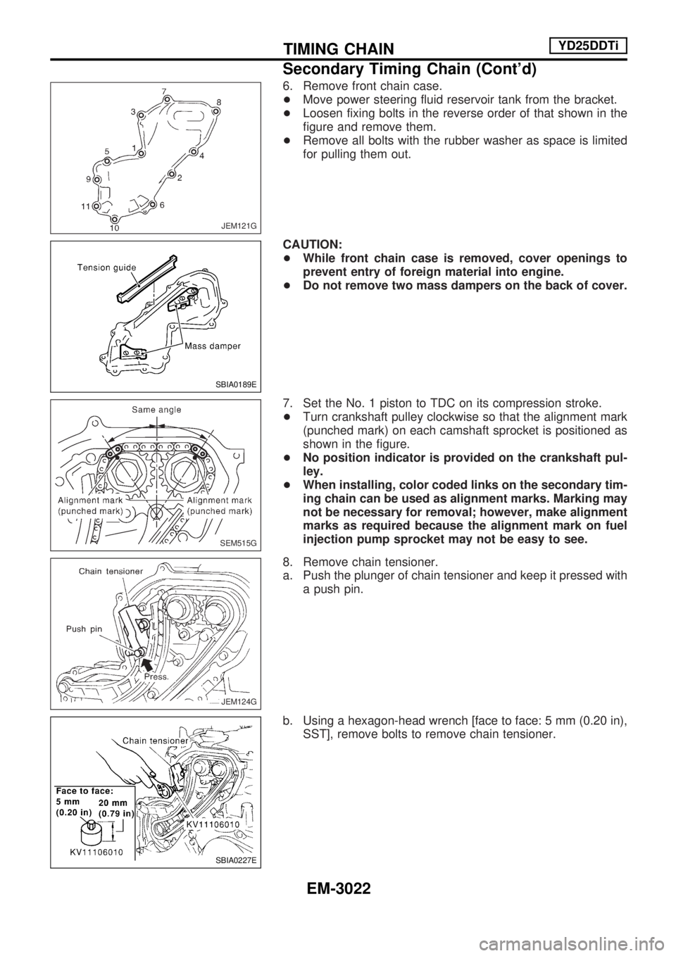
6. Remove front chain case.
+Move power steering fluid reservoir tank from the bracket.
+Loosen fixing bolts in the reverse order of that shown in the
figure and remove them.
+Remove all bolts with the rubber washer as space is limited
for pulling them out.
CAUTION:
+While front chain case is removed, cover openings to
prevent entry of foreign material into engine.
+Do not remove two mass dampers on the back of cover.
7. Set the No. 1 piston to TDC on its compression stroke.
+Turn crankshaft pulley clockwise so that the alignment mark
(punched mark) on each camshaft sprocket is positioned as
shown in the figure.
+No position indicator is provided on the crankshaft pul-
ley.
+When installing, color coded links on the secondary tim-
ing chain can be used as alignment marks. Marking may
not be necessary for removal; however, make alignment
marks as required because the alignment mark on fuel
injection pump sprocket may not be easy to see.
8. Remove chain tensioner.
a. Push the plunger of chain tensioner and keep it pressed with
a push pin.
b. Using a hexagon-head wrench [face to face: 5 mm (0.20 in),
SST], remove bolts to remove chain tensioner.
JEM121G
SBIA0189E
SEM515G
JEM124G
SBIA0227E
TIMING CHAINYD25DDTi
Secondary Timing Chain (Cont'd)
EM-3022
Page 937 of 1306
Valve Clearance
CHECKING
Check valve clearance while engine is cold and not running.
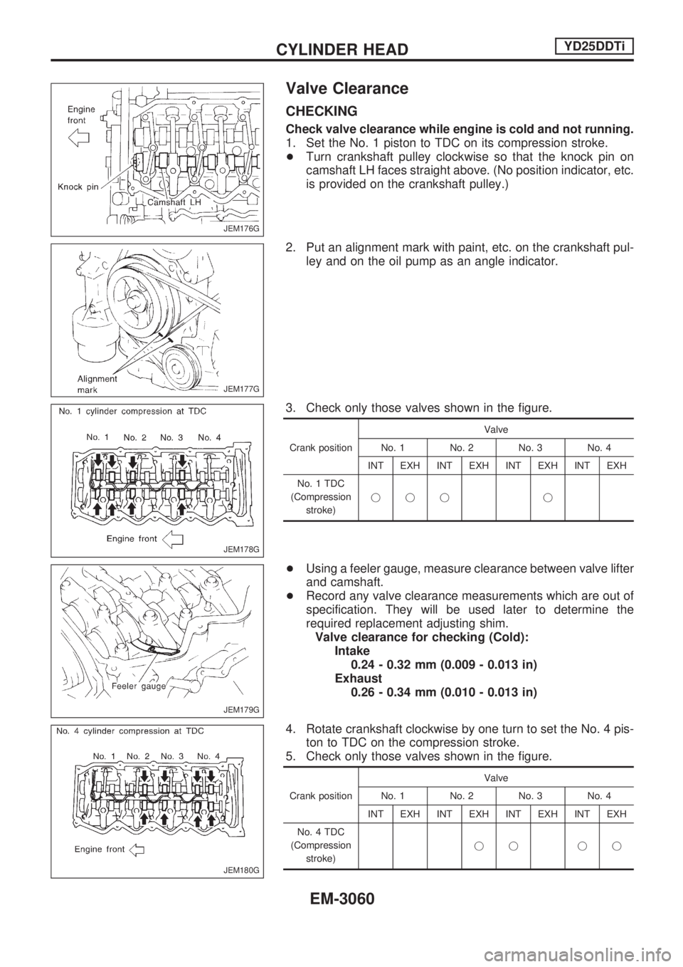
1. Set the No. 1 piston to TDC on its compression stroke.
+Turn crankshaft pulley clockwise so that the knock pin on
camshaft LH faces straight above. (No position indicator, etc.
is provided on the crankshaft pulley.)
2. Put an alignment mark with paint, etc. on the crankshaft pul-
ley and on the oil pump as an angle indicator.
3. Check only those valves shown in the figure.
Crank positionValve
No. 1 No. 2 No. 3 No. 4
INT EXH INT EXH INT EXH INT EXH
No. 1 TDC
(Compression
stroke)jjj j
+Using a feeler gauge, measure clearance between valve lifter
and camshaft.
+Record any valve clearance measurements which are out of
specification. They will be used later to determine the
required replacement adjusting shim.
Valve clearance for checking (Cold):
Intake
0.24 - 0.32 mm (0.009 - 0.013 in)
Exhaust
0.26 - 0.34 mm (0.010 - 0.013 in)
4. Rotate crankshaft clockwise by one turn to set the No. 4 pis-
ton to TDC on the compression stroke.
5. Check only those valves shown in the figure.
Crank positionValve
No. 1 No. 2 No. 3 No. 4
INT EXH INT EXH INT EXH INT EXH
No. 4 TDC
(Compression
stroke)jj jj
JEM176G
JEM177G
JEM178G
JEM179G
JEM180G
CYLINDER HEADYD25DDTi
EM-3060
Page 1007 of 1306
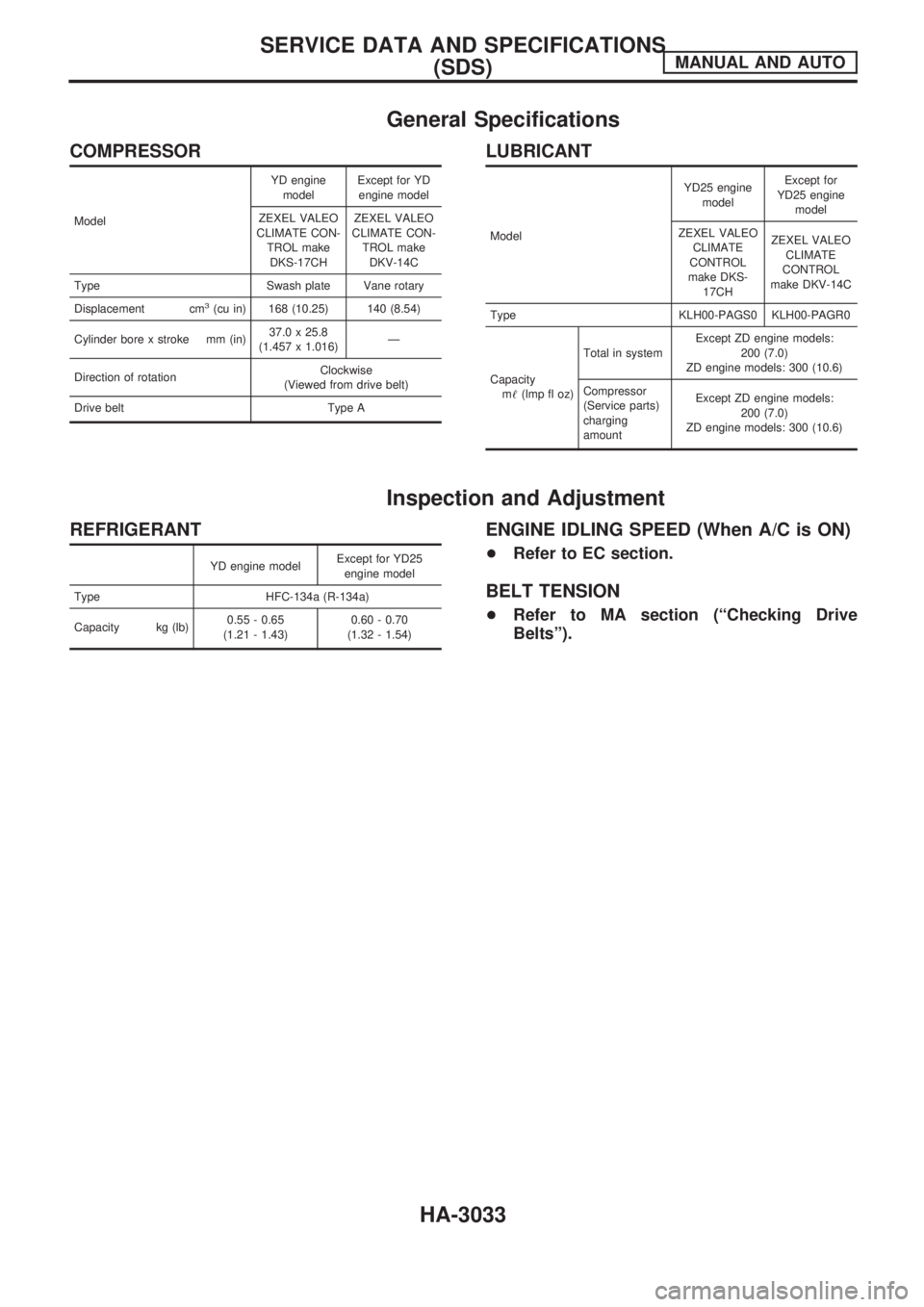
General Specifications
COMPRESSOR
ModelYD engine
modelExcept for YD
engine model
ZEXEL VALEO
CLIMATE CON-
TROL make
DKS-17CHZEXEL VALEO
CLIMATE CON-
TROL make
DKV-14C
Type Swash plate Vane rotary
Displacement cm
3(cu in) 168 (10.25) 140 (8.54)
Cylinder bore x stroke mm (in)37.0 x 25.8
(1.457 x 1.016)Ð
Direction of rotationClockwise
(Viewed from drive belt)
Drive belt Type A
LUBRICANT
ModelYD25 engine
modelExcept for
YD25 engine
model
ZEXEL VALEO
CLIMATE
CONTROL
make DKS-
17CHZEXEL VALEO
CLIMATE
CONTROL
make DKV-14C
Type KLH00-PAGS0 KLH00-PAGR0
Capacity
m!(lmp fl oz)Total in systemExcept ZD engine models:
200 (7.0)
ZD engine models: 300 (10.6)
Compressor
(Service parts)
charging
amountExcept ZD engine models:
200 (7.0)
ZD engine models: 300 (10.6)
Inspection and Adjustment
REFRIGERANT
YD engine modelExcept for YD25
engine model
Type HFC-134a (R-134a)
Capacity kg (lb)0.55 - 0.65
(1.21 - 1.43)0.60 - 0.70
(1.32 - 1.54)
ENGINE IDLING SPEED (When A/C is ON)
+Refer to EC section.
BELT TENSION
+Refer to MA section (ªChecking Drive
Beltsº).
SERVICE DATA AND SPECIFICATIONS
(SDS)MANUAL AND AUTO
HA-3033
Page 1062 of 1306
A
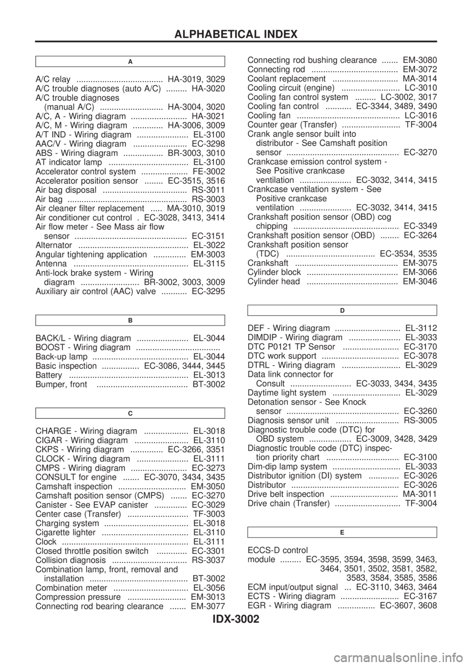
A/C relay ..................................... HA-3019, 3029
A/C trouble diagnoses (auto A/C) ......... HA-3020
A/C trouble diagnoses
(manual A/C) ........................... HA-3004, 3020
A/C, A - Wiring diagram ........................ HA-3021
A/C, M - Wiring diagram ............. HA-3006, 3009
A/T IND - Wiring diagram ...................... EL-3100
AAC/V - Wiring diagram ....................... EC-3298
ABS - Wiring diagram ................. BR-3003, 3010
AT indicator lamp .................................. EL-3100
Accelerator control system .................... FE-3002
Accelerator position sensor ........ EC-3515, 3516
Air bag disposal .................................... RS-3011
Air bag ................................................... RS-3003
Air cleaner filter replacement ..... MA-3010, 3019
Air conditioner cut control . EC-3028, 3413, 3414
Air flow meter - See Mass air flow
sensor ................................................ EC-3151
Alternator ............................................... EL-3022
Angular tightening application .............. EM-3003
Antenna ................................................. EL-3115
Anti-lock brake system - Wiring
diagram ......................... BR-3002, 3003, 3009
Auxiliary air control (AAC) valve ........... EC-3295
B
BACK/L - Wiring diagram ...................... EL-3044
BOOST - Wiring diagram ....................................
Back-up lamp ......................................... EL-3044
Basic inspection ................ EC-3086, 3444, 3445
Battery ................................................... EL-3013
Bumper, front ....................................... BT-3002
C
CHARGE - Wiring diagram ................... EL-3018
CIGAR - Wiring diagram ....................... EL-3110
CKPS - Wiring diagram .............. EC-3266, 3351
CLOCK - Wiring diagram ...................... EL-3111
CMPS - Wiring diagram ........................ EC-3273
CONSULT for engine ....... EC-3070, 3434, 3435
Camshaft inspection ............................. EM-3050
Camshaft position sensor (CMPS) ....... EC-3270
Canister - See EVAP canister .............. EC-3029
Center case (Transfer) .......................... TF-3003
Charging system .................................... EL-3018
Cigarette lighter ..................................... EL-3110
Clock ...................................................... EL-3111
Closed throttle position switch ............. EC-3301
Collision diagnosis ................................ RS-3037
Combination lamp, front, removal and
installation .......................................... BT-3002
Combination meter ................................ EL-3056
Compression pressure ......................... EM-3013
Connecting rod bearing clearance ....... EM-3077Connecting rod bushing clearance ....... EM-3080
Connecting rod ..................................... EM-3072
Coolant replacement ............................ MA-3014
Cooling circuit (engine) ......................... LC-3010
Cooling fan control system ......... LC-3002, 3017
Cooling fan control ........... EC-3344, 3489, 3490
Cooling fan ............................................ LC-3016
Counter gear (Transfer) ......................... TF-3004
Crank angle sensor built into
distributor - See Camshaft position
sensor ................................................ EC-3270
Crankcase emission control system -
See Positive crankcase
ventilation ...................... EC-3032, 3414, 3415
Crankcase ventilation system - See
Positive crankcase
ventilation ...................... EC-3032, 3414, 3415
Crankshaft position sensor (OBD) cog
chipping ............................................. EC-3349
Crankshaft position sensor (OBD) ........ EC-3264
Crankshaft position sensor
(TDC) ...................................... EC-3534, 3535
Crankshaft ............................................ EM-3075
Cylinder block ....................................... EM-3066
Cylinder head ....................................... EM-3046
D
DEF - Wiring diagram ............................ EL-3112
DIMDIP - Wiring diagram ...................... EL-3033
DTC P0121 TP Sensor ........................ EC-3170
DTC work support ................................. EC-3078
DTRL - Wiring diagram ......................... EL-3029
Data link connector for
Consult .......................... EC-3033, 3434, 3435
Daytime light system ............................. EL-3029
Detonation sensor - See Knock
sensor ................................................ EC-3260
Diagnosis sensor unit ........................... RS-3005
Diagnostic trouble code (DTC) for
OBD system .................. EC-3009, 3428, 3429
Diagnostic trouble code (DTC) inspec-
tion priority chart ............................... EC-3100
Dim-dip lamp system ............................. EL-3033
Distributor ignition (DI) system ............. EC-3026
Distributor .............................................. EC-3026
Drive belt inspection ............................. MA-3011
Drive chain (Transfer) ............................ TF-3004
E
ECCS-D control
module ......... EC-3595, 3594, 3598, 3599, 3463,
3464, 3501, 3502, 3581, 3582,
3583, 3584, 3585, 3586
ECM input/output signal ... EC-3110, 3463, 3464
ECTS - Wiring diagram ......................... EC-3167
EGR - Wiring diagram ................ EC-3607, 3608
ALPHABETICAL INDEX
IDX-3002
Page 1113 of 1306
METER AND GAUGES....................................... 3056
System Description .......................................... 3056
Combination Meter/With Tachometer .............. 3057
Combination Meter/Without Tachometer ......... 3058
Schematic/With Tachometer ............................ 3059
Schematic/Without Tachometer ....................... 3060
Construction ..................................................... 3061
Wiring Diagram - METER -/Gasoline Engine
with Tachometer .............................................. 3062
Wiring Diagram - METER -/Gasoline Engine
without Tachometer ......................................... 3064
Wiring Diagram - METER -/LHD Diesel Engine
Models with Tachometer.................................. 3065
Wiring Diagram - METER -/RHD Diesel
Engine Models with Tachometer ..................... 3067
Wiring Diagram - METER -/Diesel Engine
without Tachometer ......................................... 3069
Meter/Gauge Operation and Odo/Trip Meter
Segment Check in Diagnosis Mode ................ 3070
Trouble Diagnoses/With Tachometer .............. 3071
Trouble Diagnoses/Without Tachometer ......... 3076
WARNING LAMPS.............................................. 3081
Schematic/With Tachometer ............................ 3081
Schematic/Without Tachometer ....................... 3082
Wiring Diagram - WARN -/Gasoline Engine
with Tachometer .............................................. 3083
Wiring Diagram - WARN -/Gasoline Engine
without Tachometer ......................................... 3087
Wiring Diagram - WARN -/Diesel Engine with
Tachometer ...................................................... 3091
Wiring Diagram - WARN -/Diesel Engine
without Tachometer ......................................... 3095
A/T INDICATOR................................................... 3100
Wiring Diagram - AT/IND -/RHD Models ......... 3100
Wiring Diagram - CHIME -/LHD Models.......... 3101
Wiring Diagram - CHIME -/RHD Models ......... 3102
FRONT WIPER AND WASHER.......................... 3103
Wiring Diagram - WIPER -/Without Intermittent
for Floor-shift .................................................... 3103
Wiring Diagram - WIPER -/Without Intermittent
for RHD Column-shift Models .......................... 3106
HEADLAMP WASHER........................................ 3108
Wiring Diagram - HLC - ................................... 3108
HORN................................................................... 3109
Wiring Diagram - HORN -................................ 3109
CIGARETTE LIGHTER........................................ 3110
Wiring Diagram - CIGAR - ............................... 3110
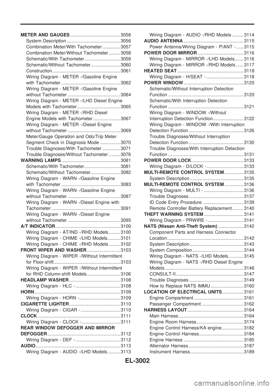
CLOCK................................................................. 3111
Wiring Diagram - CLOCK - .............................. 3111
REAR WINDOW DEFOGGER AND MIRROR
DEFOGGER......................................................... 3112
Wiring Diagram - DEF - ................................... 3112
AUDIO.................................................................. 3113
Wiring Diagram - AUDIO -/LHD Models .......... 3113Wiring Diagram - AUDIO -/RHD Models ......... 3114
AUDIO ANTENNA............................................... 3115
Power Antenna/Wiring Diagram - P/ANT - ...... 3115
POWER DOOR MIRROR.................................... 3116
Wiring Diagram - MIRROR -/LHD Models....... 3116
Wiring Diagram - MIRROR -/RHD Models ...... 3117
HEATED SEAT.................................................... 3118
Wiring Diagram - H/SEAT - ............................. 3118
POWER WINDOW............................................... 3120
Schematic/Without Interruption Detection
Function ........................................................... 3120
Schematic/With Interruption Detection
Function ........................................................... 3121
Wiring Diagram - WINDOW -/Without
Interruption Detection Function........................ 3122
Wiring Diagram - WINDOW -/With Interruption
Detection Function ........................................... 3126
Trouble Diagnoses/Without Interruption
Detection Function ........................................... 3130
Trouble Diagnoses/With Interruption Detection
Function ........................................................... 3131
POWER DOOR LOCK......................................... 3133
Wiring Diagram - D/LOCK - ............................. 3133
MULTI-REMOTE CONTROL SYSTEM............... 3135
System Description .......................................... 3135
MULTI-REMOTE CONTROL SYSTEM............... 3136
Wiring Diagram - MULTI - ............................... 3136
Trouble Diagnoses ........................................... 3137
ID Code Entry Procedure ................................ 3139
Remote Controller Battery Replacement ......... 3140
THEFT WARNING SYSTEM............................... 3141
Wiring Diagram - PRWIRE - ............................ 3141
NATS (Nissan Anti-Theft System).................... 3142
Component Parts and Harness Connector
Location............................................................ 3142
System Description .......................................... 3143
System Composition ........................................ 3144
Wiring Diagram - NATS -/LHD Models............ 3145
Wiring Diagram - NATS -/RHD Diesel Engine
Models.............................................................. 3146
CONSULT-II ..................................................... 3147
Trouble Diagnoses ........................................... 3149
How to Replace NATS IMMU .......................... 3160
LOCATION OF ELECTRICAL UNITS................. 3161
Engine Compartment ....................................... 3161
Passenger Compartment ................................. 3162
HARNESS LAYOUT............................................ 3164
Main Harness ................................................... 3164
Engine Room Harness..................................... 3174
Engine Control Harness/KA engine ................. 3182
Engine Control Harness................................... 3184
Engine Harness ............................................... 3185
Alternator Harness ........................................... 3187
Instrument Harness.......................................... 3189
EL-3002
Page 1222 of 1306

Wiring Diagram Ð CLOCK Ð
GEL430A
CLOCK
EL-3111
Page 1305 of 1306
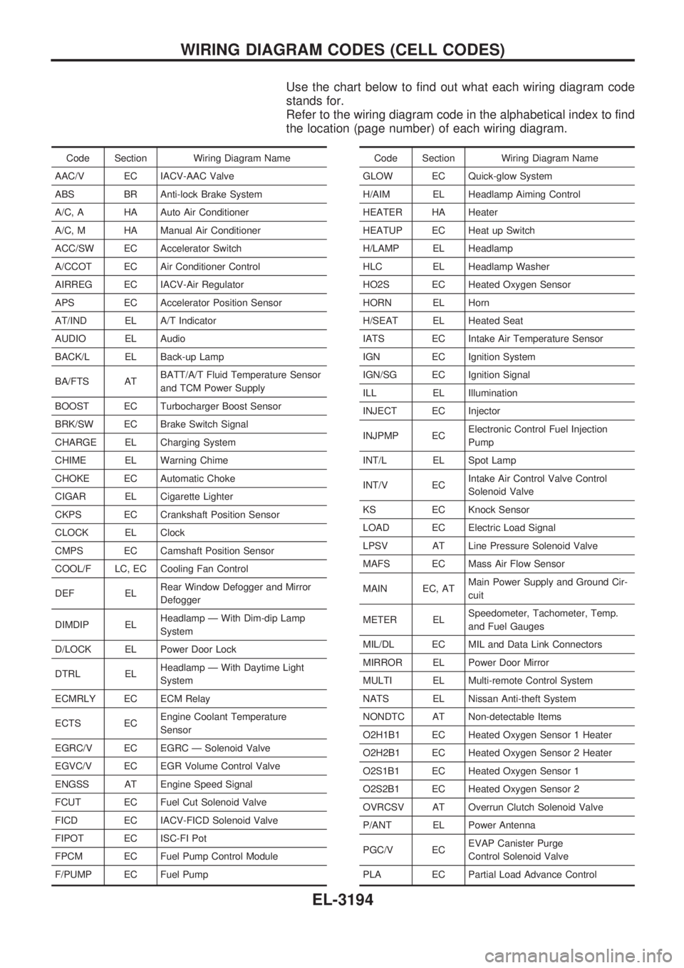
Use the chart below to find out what each wiring diagram code
stands for.
Refer to the wiring diagram code in the alphabetical index to find
the location (page number) of each wiring diagram.
Code Section Wiring Diagram Name
AAC/V EC IACV-AAC Valve
ABS BR Anti-lock Brake System
A/C, A HA Auto Air Conditioner
A/C, M HA Manual Air Conditioner
ACC/SW EC Accelerator Switch
A/CCOT EC Air Conditioner Control
AIRREG EC IACV-Air Regulator
APS EC Accelerator Position Sensor
AT/IND EL A/T Indicator
AUDIO EL Audio
BACK/L EL Back-up Lamp
BA/FTS ATBATT/A/T Fluid Temperature Sensor
and TCM Power Supply
BOOST EC Turbocharger Boost Sensor
BRK/SW EC Brake Switch Signal
CHARGE EL Charging System
CHIME EL Warning Chime
CHOKE EC Automatic Choke
CIGAR EL Cigarette Lighter
CKPS EC Crankshaft Position Sensor
CLOCK EL Clock
CMPS EC Camshaft Position Sensor
COOL/F LC, EC Cooling Fan Control
DEF ELRear Window Defogger and Mirror
Defogger
DIMDIP ELHeadlamp Ð With Dim-dip Lamp
System
D/LOCK EL Power Door Lock
DTRL ELHeadlamp Ð With Daytime Light
System
ECMRLY EC ECM Relay
ECTS ECEngine Coolant Temperature
Sensor
EGRC/V EC EGRC Ð Solenoid Valve
EGVC/V EC EGR Volume Control Valve
ENGSS AT Engine Speed Signal
FCUT EC Fuel Cut Solenoid Valve
FICD EC IACV-FICD Solenoid Valve
FIPOT EC ISC-FI Pot
FPCM EC Fuel Pump Control Module
F/PUMP EC Fuel PumpCode Section Wiring Diagram Name
GLOW EC Quick-glow System
H/AIM EL Headlamp Aiming Control
HEATER HA Heater
HEATUP EC Heat up Switch
H/LAMP EL Headlamp
HLC EL Headlamp Washer
HO2S EC Heated Oxygen Sensor
HORN EL Horn
H/SEAT EL Heated Seat
IATS EC Intake Air Temperature Sensor
IGN EC Ignition System
IGN/SG EC Ignition Signal
ILL EL Illumination
INJECT EC Injector
INJPMP ECElectronic Control Fuel Injection
Pump
INT/L EL Spot Lamp
INT/V ECIntake Air Control Valve Control
Solenoid Valve
KS EC Knock Sensor
LOAD EC Electric Load Signal
LPSV AT Line Pressure Solenoid Valve
MAFS EC Mass Air Flow Sensor
MAIN EC, ATMain Power Supply and Ground Cir-
cuit
METER ELSpeedometer, Tachometer, Temp.
and Fuel Gauges
MIL/DL EC MIL and Data Link Connectors
MIRROR EL Power Door Mirror
MULTI EL Multi-remote Control System
NATS EL Nissan Anti-theft System
NONDTC AT Non-detectable Items
O2H1B1 EC Heated Oxygen Sensor 1 Heater
O2H2B1 EC Heated Oxygen Sensor 2 Heater
O2S1B1 EC Heated Oxygen Sensor 1
O2S2B1 EC Heated Oxygen Sensor 2
OVRCSV AT Overrun Clutch Solenoid Valve
P/ANT EL Power Antenna
PGC/V ECEVAP Canister Purge
Control Solenoid Valve
PLA EC Partial Load Advance Control
WIRING DIAGRAM CODES (CELL CODES)
EL-3194