Page 2257 of 3051

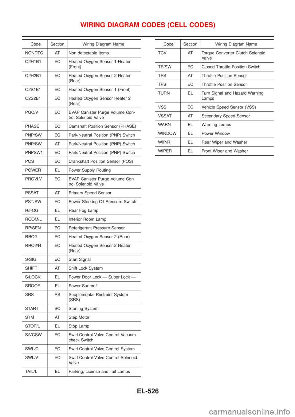
Code Section Wiring Diagram Name
NONDTC AT Non-detectable Items
O2H1B1 EC Heated Oxygen Sensor 1 Heater
(Front)
O2H2B1 EC Heated Oxygen Sensor 2 Heater
(Rear)
O2S1B1 EC Heated Oxygen Sensor 1 (Front)
O2S2B1 EC Heated Oxygen Sensor Heater 2
(Rear)
PGC/V EC EVAP Canister Purge Volume Con-
trol Solenoid Valve
PHASE EC Camshaft Position Sensor (PHASE)
PNP/SW EC Park/Neutral Position (PNP) Switch
PNP/SW AT Park/Neutral Position (PNP) Switch
PNPSW1 EC Park/Neutral Position (PNP) Switch
POS EC Crankshaft Position Sensor (POS)
POWER EL Power Supply Routing
PRGVLV EC EVAP Canister Purge Volume Con-
trol Solenoid Valve
PSSAT AT Primary Speed Sensor
PST/SW EC Power Steering Oil Pressure Switch
R/FOG EL Rear Fog Lamp
ROOM/L EL Interior Room Lamp
RP/SEN EC Referigerant Pressure Sensor
RRO2 EC Heated Oxygen Sensor 2 (Rear)
RRO2/H EC Heated Oxygen Sensor 2 Heater
(Rear)
S/SIG EC Start Signal
SHIFT AT Shift Lock System
S/LOCK EL Power Door Lock Ð Super Lock Ð
SROOF EL Power Sunroof
SRS RS Supplemental Restraint System
(SRS)
START SC Starting System
STM AT Step Motor
STOP/L EL Stop Lamp
S/VCSW EC Swirl Control Valve Control Vacuum
check Switch
SWL/C EC Swirl Control Valve Control System
SWL/V EC Swirl Control Valve Control Solenoid
Valve
TAIL/L EL Parking, License and Tail LampsCode Section Wiring Diagram Name
TCV AT Torque Converter Clutch Solenoid
Valve
TP/SW EC Closed Throttle Position Switch
TPS AT Throttle Position Sensor
TPS EC Throttle Position Sensor
TURN EL Turn Signal and Hazard Warning
Lamps
VSS EC Vehicle Speed Sensor (VSS)
VSSAT AT Secondary Speed Sensor
WARN EL Warning Lamps
WINDOW EL Power Window
WIP/R EL Rear Wiper and Washer
WIPER EL Front Wiper and Washer
WIRING DIAGRAM CODES (CELL CODES)
EL-526
Page 2540 of 3051

GENERAL INFORMATION
SECTION
GI
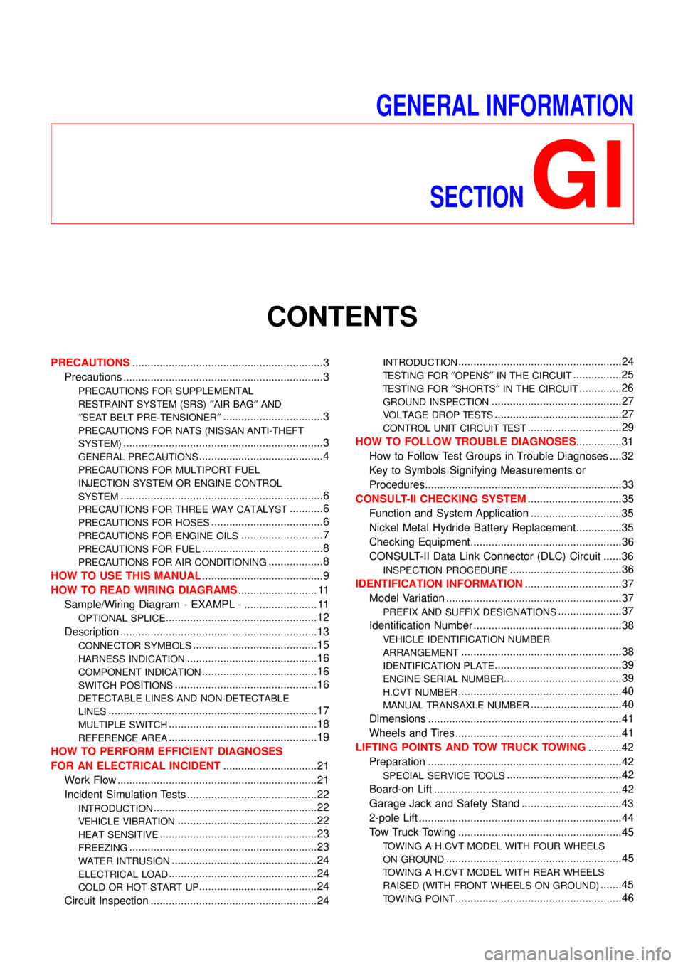
CONTENTS
PRECAUTIONS...............................................................3
Precautions ..................................................................3
PRECAUTIONS FOR SUPPLEMENTAL
RESTRAINT SYSTEM (SRS)″AIR BAG″AND
″SEAT BELT PRE-TENSIONER″
.................................3
PRECAUTIONS FOR NATS (NISSAN ANTI-THEFT
SYSTEM)
..................................................................3
GENERAL PRECAUTIONS.........................................4
PRECAUTIONS FOR MULTIPORT FUEL
INJECTION SYSTEM OR ENGINE CONTROL
SYSTEM
...................................................................6
PRECAUTIONS FOR THREE WAY CATALYST...........6
PRECAUTIONS FOR HOSES.....................................6
PRECAUTIONS FOR ENGINE OILS...........................7
PRECAUTIONS FOR FUEL........................................8
PRECAUTIONS FOR AIR CONDITIONING..................8
HOW TO USE THIS MANUAL........................................9
HOW TO READ WIRING DIAGRAMS.......................... 11
Sample/Wiring Diagram - EXAMPL - ........................ 11
OPTIONAL SPLICE..................................................12
Description .................................................................13
CONNECTOR SYMBOLS.........................................15
HARNESS INDICATION...........................................16
COMPONENT INDICATION......................................16
SWITCH POSITIONS...............................................16
DETECTABLE LINES AND NON-DETECTABLE
LINES
.....................................................................17
MULTIPLE SWITCH.................................................18
REFERENCE AREA.................................................19
HOW TO PERFORM EFFICIENT DIAGNOSES
FOR AN ELECTRICAL INCIDENT...............................21
Work Flow ..................................................................21
Incident Simulation Tests ...........................................22
INTRODUCTION......................................................22
VEHICLE VIBRATION..............................................22
HEAT SENSITIVE....................................................23
FREEZING..............................................................23
WATER INTRUSION................................................24
ELECTRICAL LOAD.................................................24
COLD OR HOT START UP.......................................24
Circuit Inspection .......................................................24
INTRODUCTION......................................................24
TESTING FOR″OPENS″IN THE CIRCUIT................25
TESTING FOR″SHORTS″IN THE CIRCUIT..............26
GROUND INSPECTION...........................................27
VOLTAGE DROP TESTS..........................................27
CONTROL UNIT CIRCUIT TEST...............................29
HOW TO FOLLOW TROUBLE DIAGNOSES...............31
How to Follow Test Groups in Trouble Diagnoses ....32
Key to Symbols Signifying Measurements or
Procedures.................................................................33
CONSULT-II CHECKING SYSTEM...............................35
Function and System Application ..............................35
Nickel Metal Hydride Battery Replacement...............35
Checking Equipment..................................................36
CONSULT-II Data Link Connector (DLC) Circuit ......36
INSPECTION PROCEDURE.....................................36
IDENTIFICATION INFORMATION................................37
Model Variation ..........................................................37
PREFIX AND SUFFIX DESIGNATIONS.....................37
Identification Number .................................................38
VEHICLE IDENTIFICATION NUMBER
ARRANGEMENT
.....................................................38
IDENTIFICATION PLATE..........................................39
ENGINE SERIAL NUMBER.......................................39
H.CVT NUMBER......................................................40
MANUAL TRANSAXLE NUMBER..............................40
Dimensions ................................................................41
Wheels and Tires .......................................................41
LIFTING POINTS AND TOW TRUCK TOWING...........42
Preparation ................................................................42
SPECIAL SERVICE TOOLS......................................42
Board-on Lift ..............................................................42
Garage Jack and Safety Stand .................................43
2-pole Lift ...................................................................44
Tow Truck Towing ......................................................45
TOWING A H.CVT MODEL WITH FOUR WHEELS
ON GROUND
..........................................................45
TOWING A H.CVT MODEL WITH REAR WHEELS
RAISED (WITH FRONT WHEELS ON GROUND)
.......45
TOWING POINT.......................................................46
Page 2550 of 3051
NLGI0003
Sample/Wiring Diagram—EXAMPL—NLGI0003S01+For Description, refer to GI-13.
SGI091A
HOW TO READ WIRING DIAGRAMS
Sample/Wiring Diagram—EXAMPL—
GI-11
Page 2551 of 3051
OPTIONAL SPLICENLGI0003S0101
SGI942
HOW TO READ WIRING DIAGRAMS
Sample/Wiring Diagram—EXAMPL—(Cont’d)
GI-12
Page 2554 of 3051
SGI364
CONNECTOR SYMBOLS=NLGI0003S0201Most of connector symbols in wiring diagrams are shown from the
terminal side.
+Connector symbols shown from the terminal side are enclosed
by a single line and followed by the direction mark.
+Connector symbols shown from the harness side are enclosed
by a double line and followed by the direction mark.
+Certain systems and components, especially those related to
OBD, may use a new style slide-locking type harness connec-
tor. For description and how to disconnect, refer to EL-5,“HAR-
NESS CONNECTOR”.
SGI363
+Male and female terminals
Connector guides for male terminals are shown in black and
female terminals in white in wiring diagrams.
HOW TO READ WIRING DIAGRAMS
Description (Cont’d)
GI-15
Page 2555 of 3051
AGI070
HARNESS INDICATIONNLGI0003S0202+Letter designations next to test meter probe indicate harness
(connector) wire color.
+Connector numbers in a single circle M33 indicate harness
connectors.
COMPONENT INDICATIONNLGI0003S0203+Connector numbers in a double circle F211 indicate compo-
nent connectors.
SGI860
SWITCH POSITIONSNLGI0003S0204Switches are shown in wiring diagrams as if the vehicle is in the
“normal”condition.
A vehicle is in the“normal”condition when:
+ignition switch is“OFF”,
+doors, hood and trunk lid/back door are closed,
+pedals are not depressed, and
+parking brake is released.
HOW TO READ WIRING DIAGRAMS
Description (Cont’d)
GI-16
Page 2556 of 3051
SGI862-A
DETECTABLE LINES AND NON-DETECTABLE LINESNLGI0003S0205In some wiring diagrams, two kinds of lines, representing wires,
with different weight are used.
+A line with regular weight (wider line) represents a“detectable
line for DTC (Diagnostic Trouble Code)”.A“detectable line for
DTC”is a circuit in which ECM can detect its malfunctions with
the on board diagnostic system.
+A line with less weight (thinner line) represents a“non-detect-
able line for DTC”.A“non-detectable line for DTC”is a circuit
in which ECM cannot detect its malfunctions with the on board
diagnostic system.
HOW TO READ WIRING DIAGRAMS
Description (Cont’d)
GI-17
Page 2557 of 3051
MULTIPLE SWITCH=NLGI0003S0206The continuity of multiple switch is described in two ways as shown
below.
+The switch chart is used in schematic diagrams.
+The switch diagram is used in wiring diagrams.
SGI875
HOW TO READ WIRING DIAGRAMS
Description (Cont’d)
GI-18