Page 156 of 3051
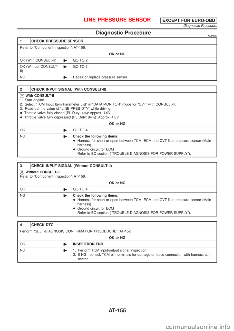
Diagnostic ProcedureNLAT0271
1 CHECK PRESSURE SENSOR
Refer to ªComponent Inspectionº, AT-156.
OK or NG
OK (With CONSULT-II)©GO TO 2.
OK (Without CONSULT-
II)©GO TO 3.
NG©Repair or replace pressure sensor.
2 CHECK INPUT SIGNAL (With CONSULT-II)
With CONSULT-II
1. Start engine.
2. Select ªTCM Input Item Parameter Listº in ªDATA MONITORº mode for ªCVTº with CONSULT-II.
3. Read out the value of ªLINE PRES DTYº while driving.
+Throttle valve fully closed (PL Duty: 4%): Approx. 1.0V
+Throttle valve fully depressed (PL Duty: 94%): Approx. 4.0V
OK or NG
OK©GO TO 4.
NG©Check the following items:
+Harness for short or open between TCM, ECM and CVT fluid pressure sensor (Main
harness)
+Ground circuit for ECM
Refer to EC section (ªTROUBLE DIAGNOSIS FOR POWER SUPPLYº).
3 CHECK INPUT SIGNAL (Without CONSULT-II)
Without CONSULT-II
Refer to ªComponent Inspectionº, AT-156.
OK or NG
OK©GO TO 4.
NG©Check the following items:
+Harness for short or open between TCM, ECM and CVT fluid pressure sensor (Main
harness).
+Ground circuit for ECM
Refer to EC section (ªTROUBLE DIAGNOSIS FOR POWER SUPPLYº).
4 CHECK DTC
Perform ªSELF-DIAGNOSIS CONFIRMATION PROCEDUREº, AT-152.
OK or NG
OK©INSPECTION END
NG©1. Perform TCM input/output signal inspection.
2. If NG, recheck TCM pin terminals for damage or loose connection with harness con-
nector.
LINE PRESSURE SENSOREXCEPT FOR EURO-OBD
Diagnostic Procedure
AT-155
Page 157 of 3051
SAT265K
Component Inspection=NLAT0272LINE PRESSURE SENSORNLAT0272S01+Start engine.
+Check voltage between terminals 1 and 6, 10 and 6.
Terminal No. Voltage
1 6 Approx. 0.5 - 4.5V
10 6 Approx. 4.5 - 5.5V
LINE PRESSURE SENSOREXCEPT FOR EURO-OBD
Component Inspection
AT-156
Page 158 of 3051
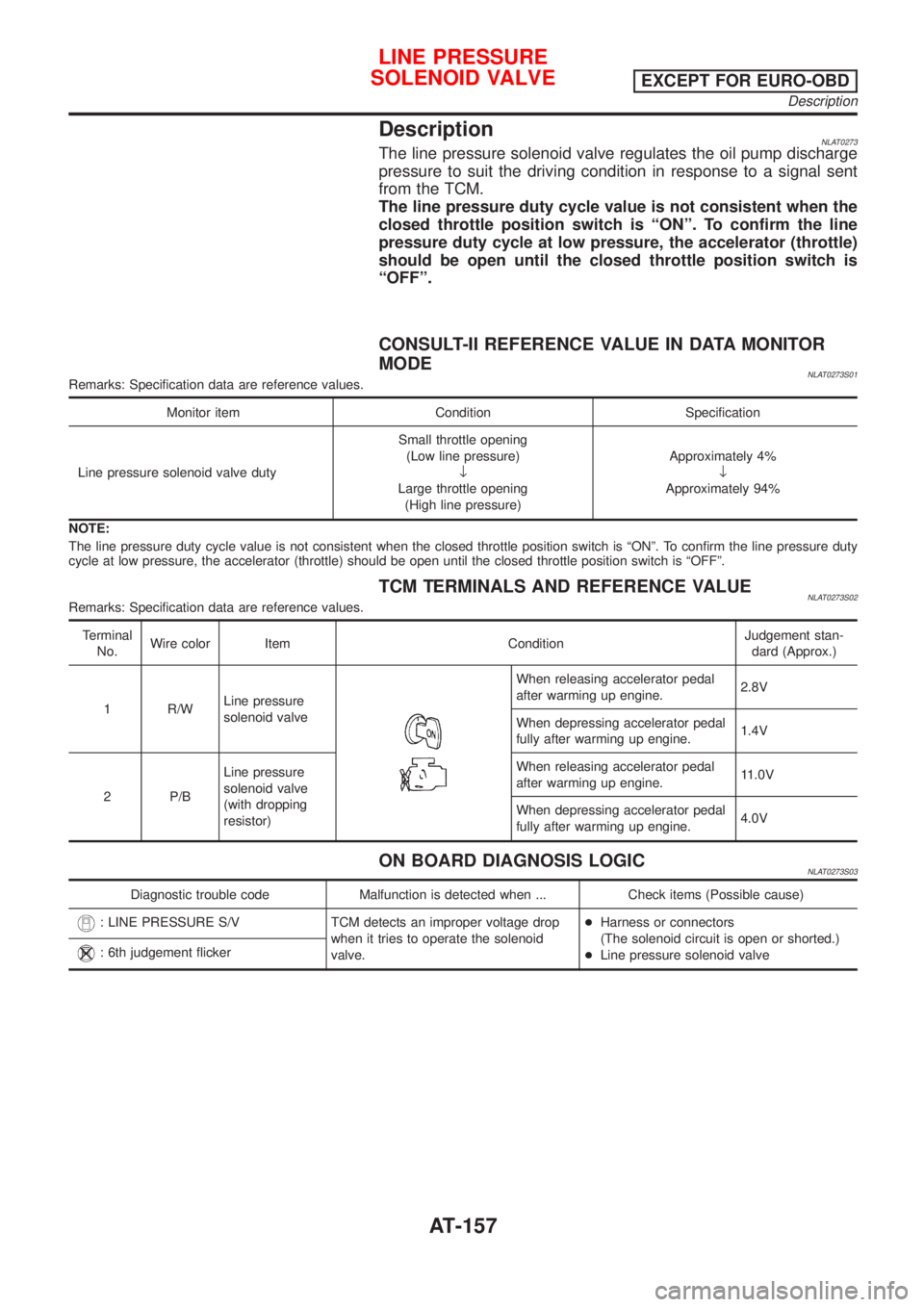
DescriptionNLAT0273The line pressure solenoid valve regulates the oil pump discharge
pressure to suit the driving condition in response to a signal sent
from the TCM.
The line pressure duty cycle value is not consistent when the
closed throttle position switch is ªONº. To confirm the line
pressure duty cycle at low pressure, the accelerator (throttle)
should be open until the closed throttle position switch is
ªOFFº.
CONSULT-II REFERENCE VALUE IN DATA MONITOR
MODE
NLAT0273S01Remarks: Specification data are reference values.
Monitor item Condition Specification
Line pressure solenoid valve dutySmall throttle opening
(Low line pressure)
¯
Large throttle opening
(High line pressure)Approximately 4%
¯
Approximately 94%
NOTE:
The line pressure duty cycle value is not consistent when the closed throttle position switch is ªONº. To confirm the line pressure duty
cycle at low pressure, the accelerator (throttle) should be open until the closed throttle position switch is ªOFFº.
TCM TERMINALS AND REFERENCE VALUENLAT0273S02Remarks: Specification data are reference values.
Terminal
No.Wire color Item ConditionJudgement stan-
dard (Approx.)
1 R/WLine pressure
solenoid valve
When releasing accelerator pedal
after warming up engine.2.8V
When depressing accelerator pedal
fully after warming up engine.1.4V
2 P/BLine pressure
solenoid valve
(with dropping
resistor)When releasing accelerator pedal
after warming up engine.11.0V
When depressing accelerator pedal
fully after warming up engine.4.0V
ON BOARD DIAGNOSIS LOGICNLAT0273S03
Diagnostic trouble code Malfunction is detected when ... Check items (Possible cause)
: LINE PRESSURE S/V TCM detects an improper voltage drop
when it tries to operate the solenoid
valve.+Harness or connectors
(The solenoid circuit is open or shorted.)
+Line pressure solenoid valve
: 6th judgement flicker
LINE PRESSURE
SOLENOID VALVE
EXCEPT FOR EURO-OBD
Description
AT-157
Page 161 of 3051
Diagnostic ProcedureNLAT0275
1 CHECK VALVE RESISTANCE
1. Turn ignition switch to ªOFFº position.
2. Disconnect terminal cord assembly connector in engine compartment.
3. Check resistance between terminal 8 and ground.
Resistance:
2.5-5W
SAT686JA
OK or NG
OK©GO TO 2.
NG©1. Remove control valve assembly. Refer to AT-206.
2. Check the following items:
+Line pressure solenoid valve
Refer to ªComponent Inspectionº, AT-163.
+Harness of terminal cord assembly for short or open
LINE PRESSURE
SOLENOID VALVE
EXCEPT FOR EURO-OBD
Diagnostic Procedure
AT-160
Page 165 of 3051
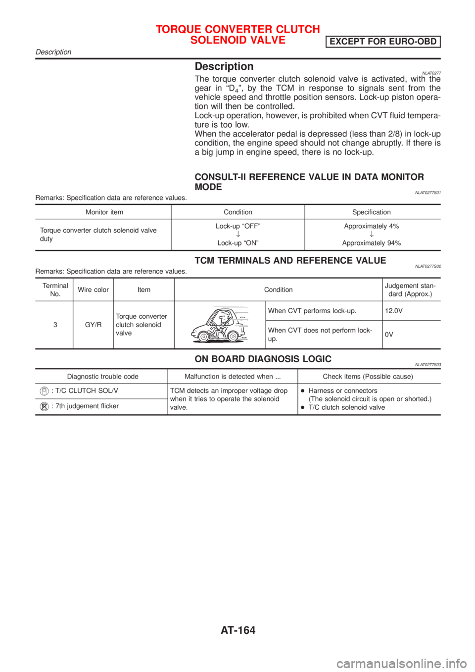
DescriptionNLAT0277The torque converter clutch solenoid valve is activated, with the
gear in ªD
4º, by the TCM in response to signals sent from the
vehicle speed and throttle position sensors. Lock-up piston opera-
tion will then be controlled.
Lock-up operation, however, is prohibited when CVT fluid tempera-
ture is too low.
When the accelerator pedal is depressed (less than 2/8) in lock-up
condition, the engine speed should not change abruptly. If there is
a big jump in engine speed, there is no lock-up.
CONSULT-II REFERENCE VALUE IN DATA MONITOR
MODE
NLAT0277S01Remarks: Specification data are reference values.
Monitor item Condition Specification
Torque converter clutch solenoid valve
dutyLock-up ªOFFº
¯
Lock-up ªONºApproximately 4%
¯
Approximately 94%
TCM TERMINALS AND REFERENCE VALUENLAT0277S02Remarks: Specification data are reference values.
Terminal
No.Wire color Item ConditionJudgement stan-
dard (Approx.)
3 GY/RTorque converter
clutch solenoid
valve
When CVT performs lock-up. 12.0V
When CVT does not perform lock-
up.0V
ON BOARD DIAGNOSIS LOGICNLAT0277S03
Diagnostic trouble code Malfunction is detected when ... Check items (Possible cause)
: T/C CLUTCH SOL/V TCM detects an improper voltage drop
when it tries to operate the solenoid
valve.+Harness or connectors
(The solenoid circuit is open or shorted.)
+T/C clutch solenoid valve
: 7th judgement flicker
TORQUE CONVERTER CLUTCH
SOLENOID VALVE
EXCEPT FOR EURO-OBD
Description
AT-164
Page 168 of 3051
Diagnostic ProcedureNLAT0279
1 CHECK VALVE RESISTANCE
1. Turn ignition switch to ªOFFº position.
2. Disconnect terminal cord assembly connector in engine compartment.
3. Check resistance between terminal 9 and ground.
Resistance:
10-20W
SAT269K
OK or NG
OK©GO TO 2.
NG©1. Remove oil pan. Refer to AT-206.
2. Check the following items:
+Torque converter clutch solenoid valve
Refer to ªComponent Inspectionº, AT-169.
+Harness of terminal cord assembly for short or open
TORQUE CONVERTER CLUTCH
SOLENOID VALVE
EXCEPT FOR EURO-OBD
Diagnostic Procedure
AT-167
Page 175 of 3051
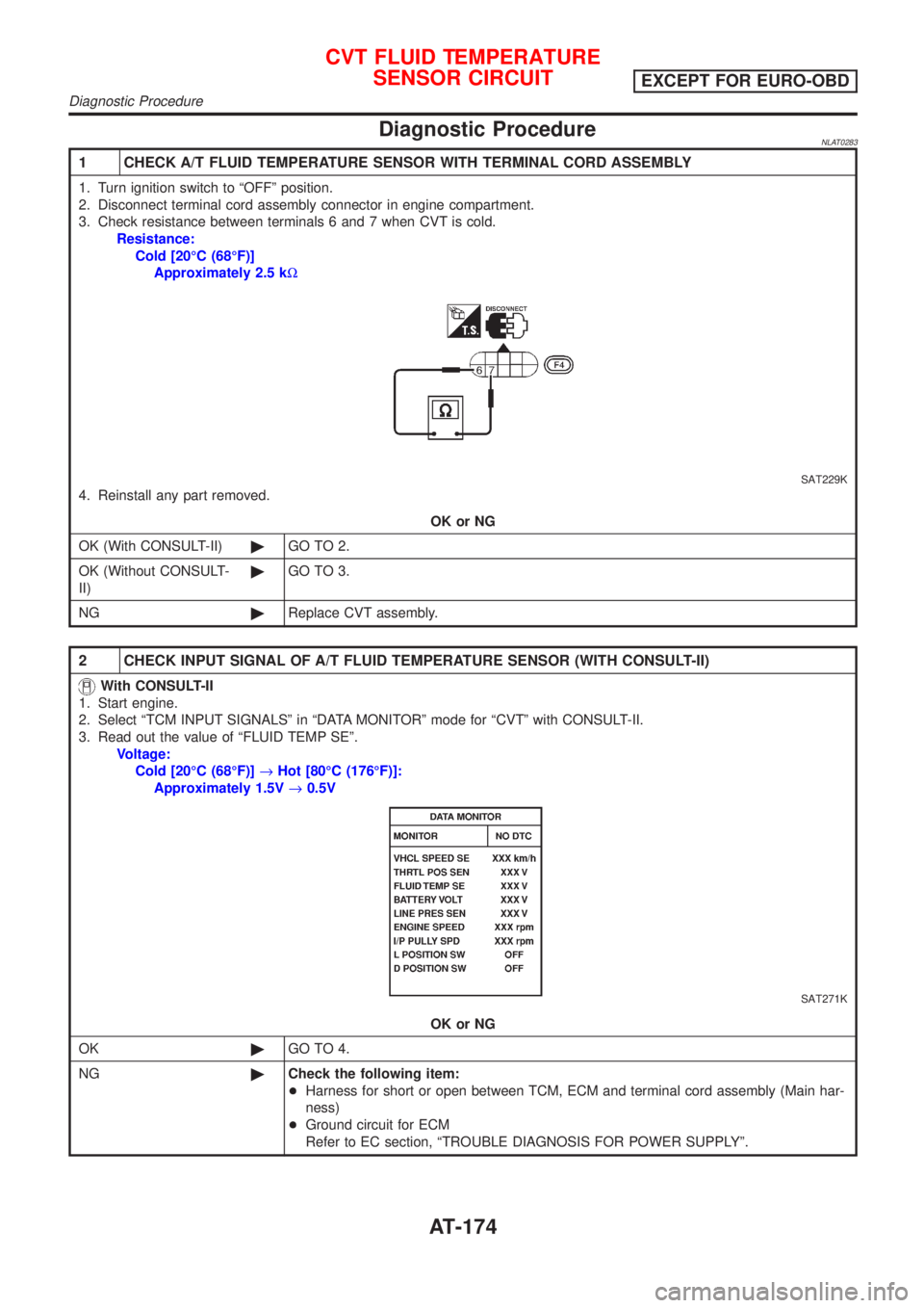
Diagnostic ProcedureNLAT0283
1 CHECK A/T FLUID TEMPERATURE SENSOR WITH TERMINAL CORD ASSEMBLY
1. Turn ignition switch to ªOFFº position.
2. Disconnect terminal cord assembly connector in engine compartment.
3. Check resistance between terminals 6 and 7 when CVT is cold.
Resistance:
Cold [20ÉC (68ÉF)]
Approximately 2.5 kW
SAT229K
4. Reinstall any part removed.
OK or NG
OK (With CONSULT-II)©GO TO 2.
OK (Without CONSULT-
II)©GO TO 3.
NG©Replace CVT assembly.
2 CHECK INPUT SIGNAL OF A/T FLUID TEMPERATURE SENSOR (WITH CONSULT-II)
With CONSULT-II
1. Start engine.
2. Select ªTCM INPUT SIGNALSº in ªDATA MONITORº mode for ªCVTº with CONSULT-II.
3. Read out the value of ªFLUID TEMP SEº.
Voltage:
Cold [20ÉC (68ÉF)]®Hot [80ÉC (176ÉF)]:
Approximately 1.5V®0.5V
SAT271K
OK or NG
OK©GO TO 4.
NG©Check the following item:
+Harness for short or open between TCM, ECM and terminal cord assembly (Main har-
ness)
+Ground circuit for ECM
Refer to EC section, ªTROUBLE DIAGNOSIS FOR POWER SUPPLYº.
CVT FLUID TEMPERATURE
SENSOR CIRCUIT
EXCEPT FOR EURO-OBD
Diagnostic Procedure
AT-174
Page 176 of 3051
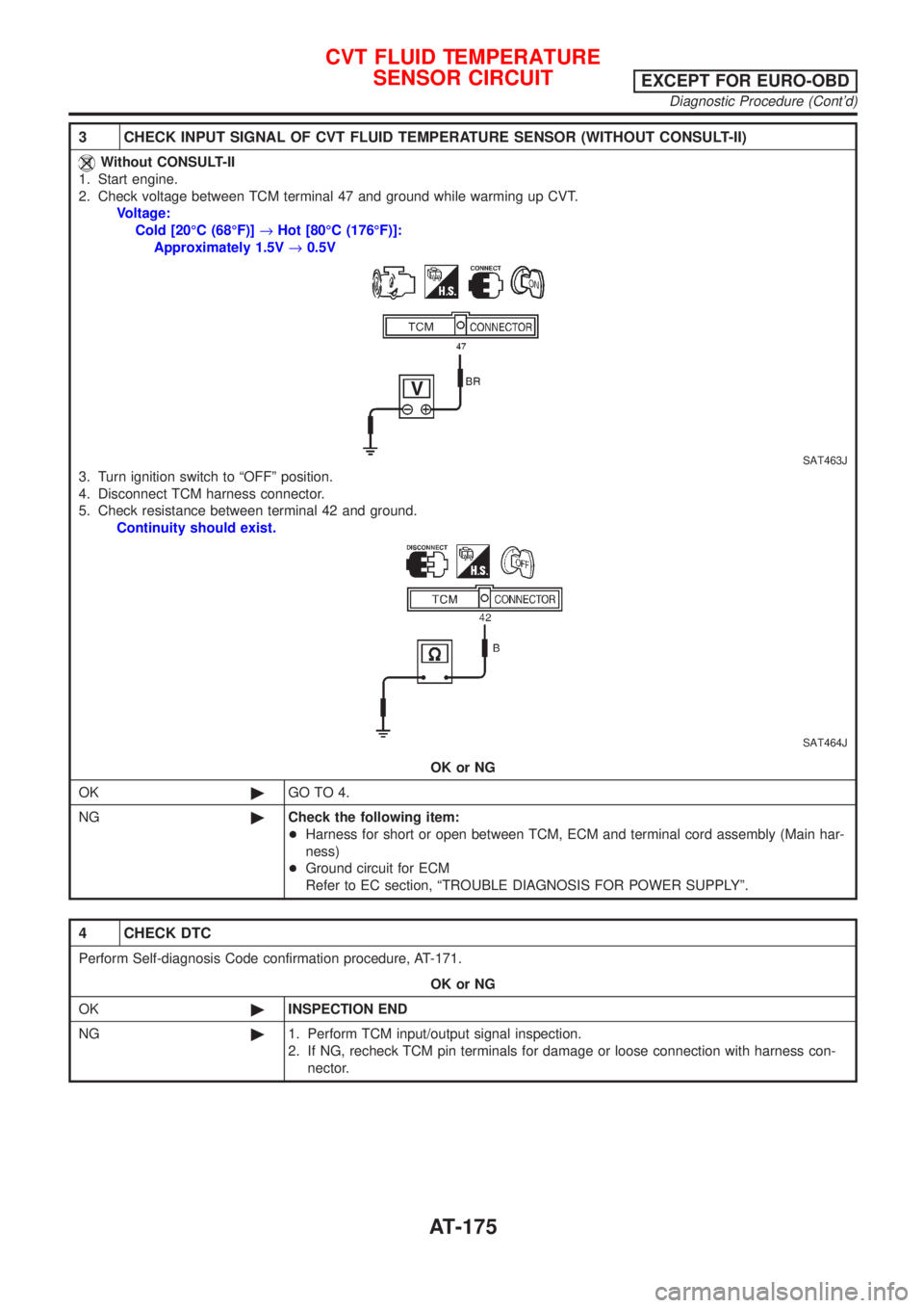
3 CHECK INPUT SIGNAL OF CVT FLUID TEMPERATURE SENSOR (WITHOUT CONSULT-II)
Without CONSULT-II
1. Start engine.
2. Check voltage between TCM terminal 47 and ground while warming up CVT.
Voltage:
Cold [20ÉC (68ÉF)]®Hot [80ÉC (176ÉF)]:
Approximately 1.5V®0.5V
SAT463J
3. Turn ignition switch to ªOFFº position.
4. Disconnect TCM harness connector.
5. Check resistance between terminal 42 and ground.
Continuity should exist.
SAT464J
OK or NG
OK©GO TO 4.
NG©Check the following item:
+Harness for short or open between TCM, ECM and terminal cord assembly (Main har-
ness)
+Ground circuit for ECM
Refer to EC section, ªTROUBLE DIAGNOSIS FOR POWER SUPPLYº.
4 CHECK DTC
Perform Self-diagnosis Code confirmation procedure, AT-171.
OK or NG
OK©INSPECTION END
NG©1. Perform TCM input/output signal inspection.
2. If NG, recheck TCM pin terminals for damage or loose connection with harness con-
nector.
CVT FLUID TEMPERATURE
SENSOR CIRCUIT
EXCEPT FOR EURO-OBD
Diagnostic Procedure (Cont'd)
AT-175