2001 NISSAN ALMERA TINO oil temperature
[x] Cancel search: oil temperaturePage 2269 of 3051
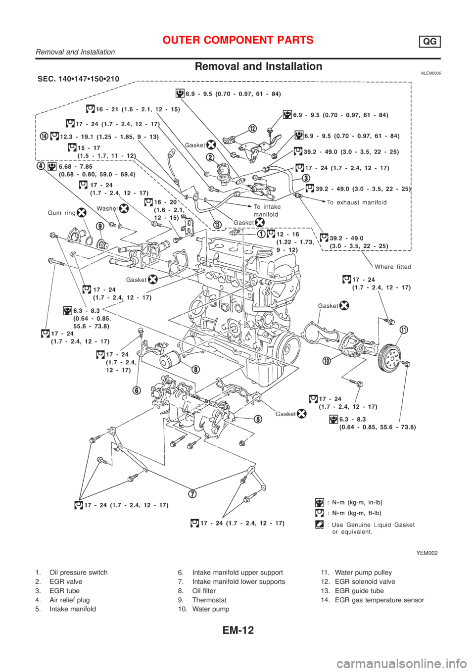
Removal and InstallationNLEM0006
YEM002
1. Oil pressure switch
2. EGR valve
3. EGR tube
4. Air relief plug
5. Intake manifold6. Intake manifold upper support
7. Intake manifold lower supports
8. Oil filter
9. Thermostat
10. Water pump11. Water pump pulley
12. EGR solenoid valve
13. EGR guide tube
14. EGR gas temperature sensor
OUTER COMPONENT PARTSQG
Removal and Installation
EM-12
Page 2272 of 3051
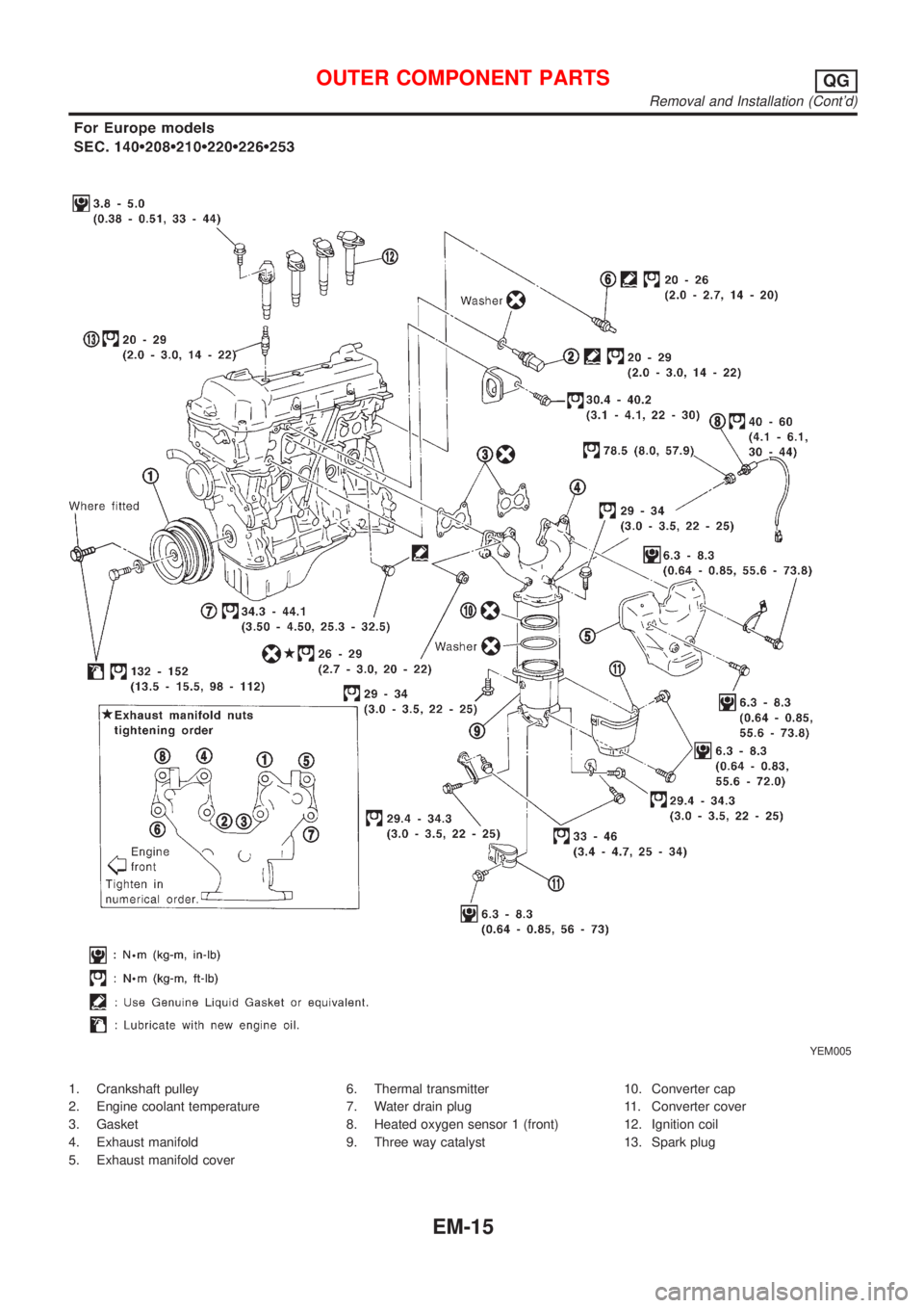
YEM005
1. Crankshaft pulley
2. Engine coolant temperature
3. Gasket
4. Exhaust manifold
5. Exhaust manifold cover6. Thermal transmitter
7. Water drain plug
8. Heated oxygen sensor 1 (front)
9. Three way catalyst10. Converter cap
11. Converter cover
12. Ignition coil
13. Spark plug
OUTER COMPONENT PARTSQG
Removal and Installation (Cont'd)
EM-15
Page 2302 of 3051
Unit: mm (in)
For adjusting For checking
HotCold* (reference
data)Hot
Intake0.32 - 0.40
(0.013 - 0.016)0.25 - 0.33
(0.010 - 0.013)0.21 - 0.49
(0.008 - 0.019)
Exhaust0.37 - 0.45
(0.015 - 0.018)0.32 - 0.40
(0.013 - 0.016)0.30 - 0.58
(0.012 - 0.023)
*: At a temperature of approximately 20ÉC (68ÉF)
Whenever valve clearances are adjusted to cold specifications, check that
the clearances satisfy hot specifications and adjust again if necessary.
AEM293
AssemblyNLEM00201. Install valve component parts.
+Always use new valve oil seal. Refer to EM-31.
+Before installing valve oil seal, install valve spring seat.
+After installing valve components, tap valve stem tip with
a plastic hammer to assure a proper fit.
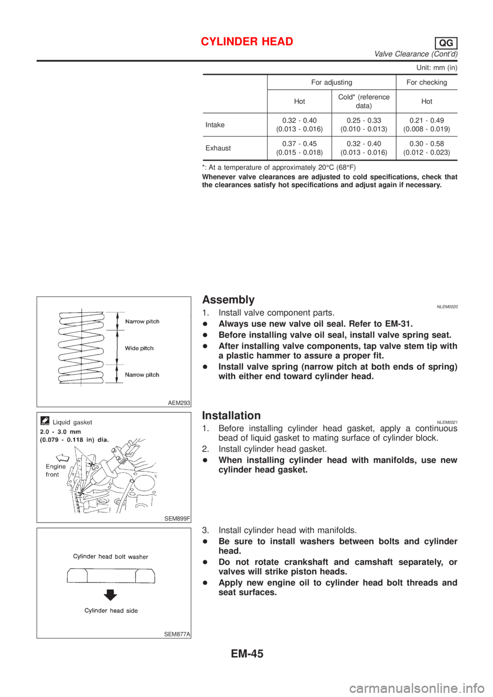
+Install valve spring (narrow pitch at both ends of spring)
with either end toward cylinder head.
SEM899F
InstallationNLEM00211. Before installing cylinder head gasket, apply a continuous
bead of liquid gasket to mating surface of cylinder block.
2. Install cylinder head gasket.
+When installing cylinder head with manifolds, use new
cylinder head gasket.
SEM877A
3. Install cylinder head with manifolds.
+Be sure to install washers between bolts and cylinder
head.
+Do not rotate crankshaft and camshaft separately, or
valves will strike piston heads.
+Apply new engine oil to cylinder head bolt threads and
seat surfaces.
CYLINDER HEADQG
Valve Clearance (Cont'd)
EM-45
Page 2310 of 3051
Removal and InstallationNLEM0024CAUTION:
+When installing sliding parts such as bearings and
pistons, apply engine oil on the sliding surfaces.
+Place removed parts, such as bearings and bearing caps,
in their proper order and direction.
+When installing connecting rod nuts and main bearing cap
bolts, apply new engine oil to threads and seating sur-
faces.
+Do not allow any magnetic materials to contact the signal
plate teeth of flywheel or drive plate, and rear plate.
+Remove the crankshaft position sensor (POS).
+Be careful not to damage sensor edges and single plate
teeth.
SEM927F
DisassemblyNLEM0025PISTON AND CRANKSHAFTNLEM0025S011. Place engine on a work stand.
2. Drain coolant and oil.
3. Remove timing chain.
Refer to EM-23.
SEM877B
4. Remove pistons with connecting rod.
+When disassembling piston and connecting rod, remove snap
ring first. Then heat piston to 60 to 70ÉC (140 to 158ÉF) or use
piston pin press stand at room temperature.
CAUTION:
+When piston rings are not replaced, make sure that piston
rings are mounted in their original positions.
+When replacing piston rings, if there is no punch mark,
install with either side up.
SEM165DB
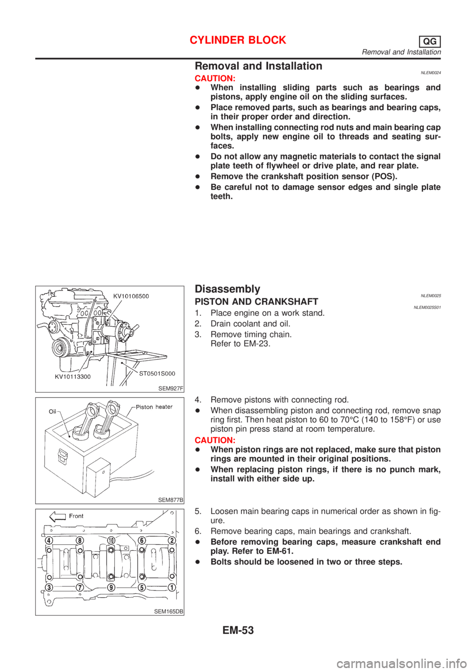
5. Loosen main bearing caps in numerical order as shown in fig-
ure.
6. Remove bearing caps, main bearings and crankshaft.
+Before removing bearing caps, measure crankshaft end
play. Refer to EM-61.
+Bolts should be loosened in two or three steps.
CYLINDER BLOCKQG
Removal and Installation
EM-53
Page 2410 of 3051
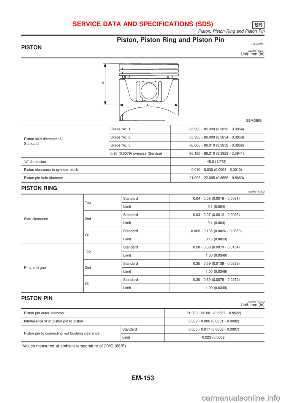
Piston, Piston Ring and Piston Pin=NLEM0151PISTONNLEM0151S01Unit: mm (in)
SEM086G
Piston skirt diameter ªAº
StandardGrade No. 1 85.980 - 85.990 (3.3850 - 3.3854)
Grade No. 2 85.990 - 86.000 (3.3854 - 3.3858)
Grade No. 3 86.000 - 86.010 (3.3858 - 3.3862)
0.20 (0.0079) oversize (Service) 86.180 - 86.210 (3.3929 - 3.3941)
ªaº dimension45.0 (1.772)
Piston clearance to cylinder block 0.010 - 0.030 (0.0004 - 0.0012)
Piston pin hole diameter21.993 - 22.005 (0.8659 - 0.8663)
PISTON RINGNLEM0151S02
Side clearanceTo pStandard 0.04 - 0.08 (0.0016 - 0.0031)
Limit 0.1 (0.004)
2ndStandard 0.03 - 0.07 (0.0012 - 0.0028)
Limit 0.1 (0.004)
OilStandard 0.065 - 0.135 (0.0026 - 0.0053)
Limit 0.15 (0.0059)
Ring end gapTo pStandard 0.20 - 0.39 (0.0079 - 0.0154)
Limit 1.00 (0.0349)
2ndStandard 0.35 - 0.59 (0.0138 - 0.0232)
Limit 1.00 (0.0349)
OilStandard 0.20 - 0.69 (0.0079 - 0.0272)
Limit 1.00 (0.0349)
PISTON PINNLEM0151S03Unit: mm (in)
Piston pin outer diameter21.989 - 22.001 (0.8657 - 0.8622)
Interference fit of piston pin to piston 0.002 - 0.006 (0.0001 - 0.0002)
Piston pin to connecting rod bushing clearanceStandard 0.005 - 0.017 (0.0002 - 0.0007)
Limit 0.023 (0.0009)
*Values measured at ambient temperature of 20ÉC (68ÉF)
SERVICE DATA AND SPECIFICATIONS (SDS)SR
Piston, Piston Ring and Piston Pin
EM-153
Page 2506 of 3051
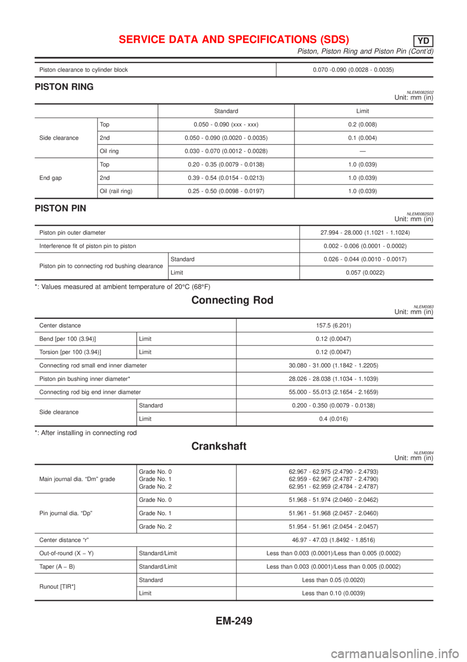
Piston clearance to cylinder block 0.070 -0.090 (0.0028 - 0.0035)
PISTON RINGNLEM0082S02Unit: mm (in)
Standard Limit
Side clearanceTop 0.050 - 0.090 (xxx - xxx) 0.2 (0.008)
2nd 0.050 - 0.090 (0.0020 - 0.0035) 0.1 (0.004)
Oil ring 0.030 - 0.070 (0.0012 - 0.0028) Ð
End gapTop 0.20 - 0.35 (0.0079 - 0.0138) 1.0 (0.039)
2nd 0.39 - 0.54 (0.0154 - 0.0213) 1.0 (0.039)
Oil (rail ring) 0.25 - 0.50 (0.0098 - 0.0197) 1.0 (0.039)
PISTON PINNLEM0082S03Unit: mm (in)
Piston pin outer diameter27.994 - 28.000 (1.1021 - 1.1024)
Interference fit of piston pin to piston 0.002 - 0.006 (0.0001 - 0.0002)
Piston pin to connecting rod bushing clearanceStandard 0.026 - 0.044 (0.0010 - 0.0017)
Limit 0.057 (0.0022)
*: Values measured at ambient temperature of 20ÉC (68ÉF)
Connecting RodNLEM0083Unit: mm (in)
Center distance157.5 (6.201)
Bend [per 100 (3.94)] Limit 0.12 (0.0047)
Torsion [per 100 (3.94)] Limit 0.12 (0.0047)
Connecting rod small end inner diameter 30.080 - 31.000 (1.1842 - 1.2205)
Piston pin bushing inner diameter* 28.026 - 28.038 (1.1034 - 1.1039)
Connecting rod big end inner diameter 55.000 - 55.013 (2.1654 - 2.1659)
Side clearanceStandard 0.200 - 0.350 (0.0079 - 0.0138)
Limit 0.4 (0.016)
*: After installing in connecting rod
CrankshaftNLEM0084Unit: mm (in)
Main journal dia. ªDmº gradeGrade No. 0
Grade No. 1
Grade No. 262.967 - 62.975 (2.4790 - 2.4793)
62.959 - 62.967 (2.4787 - 2.4790)
62.951 - 62.959 (2.4784 - 2.4787)
Pin journal dia. ªDpºGrade No. 0 51.968 - 51.974 (2.0460 - 2.0462)
Grade No. 1 51.961 - 51.968 (2.0457 - 2.0460)
Grade No. 2 51.954 - 51.961 (2.0454 - 2.0457)
Center distance ªrº46.97 - 47.03 (1.8492 - 1.8516)
Out-of-round (X þ Y) Standard/Limit Less than 0.003 (0.0001)/Less than 0.005 (0.0002)
Taper (A þ B) Standard/Limit Less than 0.003 (0.0001)/Less than 0.005 (0.0002)
Runout [TIR*]Standard Less than 0.05 (0.0020)
Limit Less than 0.10 (0.0039)
SERVICE DATA AND SPECIFICATIONS (SDS)YD
Piston, Piston Ring and Piston Pin (Cont'd)
EM-249
Page 2547 of 3051
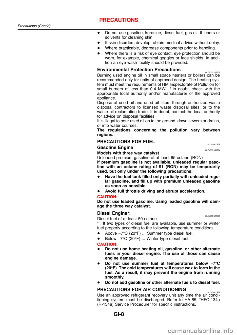
+Do not use gasoline, kerosine, diesel fuel, gas oil, thinners or
solvents for cleaning skin.
+If skin disorders develop, obtain medical advice without delay.
+Where practicable, degrease components prior to handling.
+Where there is a risk of eye contact, eye protection should be
worn, for example, chemical goggles or face shields; in addi-
tion an eye wash facility should be provided.
Environmental Protection PrecautionsNLGI0001S0702Burning used engine oil in small space heaters or boilers can be
recommended only for units of approved design. The heating sys-
tem must meet the requirements of HM Inspectorate of Pollution for
small burners of less than 0.4 MW. If in doubt, check with the
appropriate local authority and/or manufacturer of the approved
appliance.
Dispose of used oil and used oil filters through authorized waste
disposal contractors to licensed waste disposal sites, or to the
waste oil reclamation trade. If in doubt, contact the local authority
for advice on disposal facilities.
It is illegal to pour used oil on to the ground, down sewers or drains,
or into water courses.
The regulations concerning the pollution vary between
regions.
PRECAUTIONS FOR FUELNLGI0001S08Gasoline EngineNLGI0001S0804Models with three way catalyst
Unleaded premium gasoline of at least 95 octane (RON)
If premium gasoline is not available, unleaded regular gaso-
line with an octane rating of 91 (RON) may be temporarily
used, but only under the following precautions:
+Have the fuel tank filled only partially with unleaded regu-
lar gasoline, and fill up with premium unleaded gasoline
as soon as possible.
+Avoid full throttle driving and abrupt acceleration.
CAUTION:
Do not use leaded gasoline. Using leaded gasoline will dam-
age the three way catalyst.
Diesel Engine*:NLGI0001S0805Diesel fuel of at least 50 cetane
* If two types of diesel fuel are available, use summer or winter
fuel properly according to the following temperature conditions.
+Above �7°C (20°F) ... Summer type diesel fuel.
+Below �7°C (20°F) ... Winter type diesel fuel.
CAUTION:
+Do not use home heating oil, gasoline, or other alternate
fuels in your diesel engine. The use of those can cause
engine damage.
+Do not use summer fuel at temperatures below �7°C
(20°F). The cold temperatures will cause wax to form in the
fuel. As a result, it may prevent the engine from running
smoothly.
+Do not add gasoline or other alternate fuels to diesel fuel.
PRECAUTIONS FOR AIR CONDITIONINGNLGI0001S09Use an approved refrigerant recovery unit any time the air condi-
tioning system must be discharged. Refer to HA-85, “HFC-134a
(R-134a) Service Procedure” for specific instructions.
PRECAUTIONS
Precautions (Cont’d)
GI-8
Page 2596 of 3051
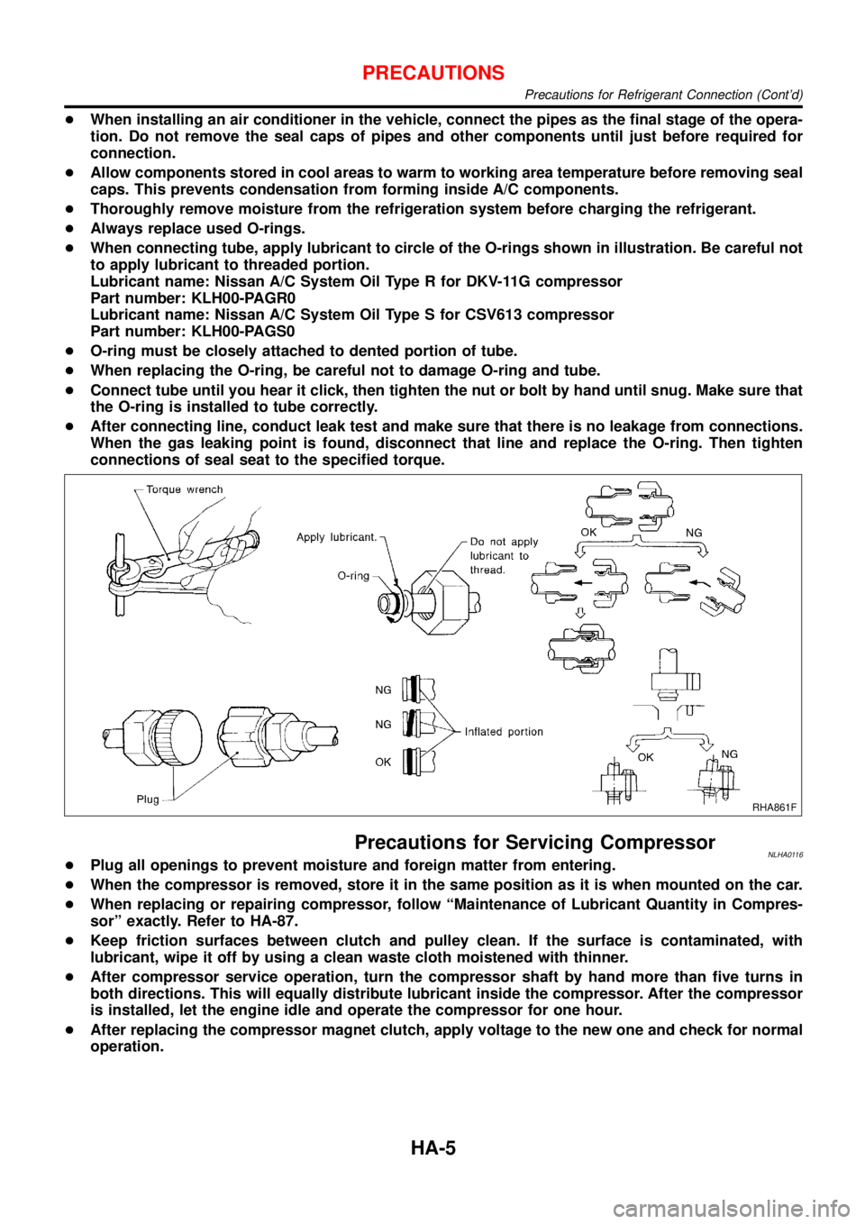
+When installing an air conditioner in the vehicle, connect the pipes as the final stage of the opera-
tion. Do not remove the seal caps of pipes and other components until just before required for
connection.
+Allow components stored in cool areas to warm to working area temperature before removing seal
caps. This prevents condensation from forming inside A/C components.
+Thoroughly remove moisture from the refrigeration system before charging the refrigerant.
+Always replace used O-rings.
+When connecting tube, apply lubricant to circle of the O-rings shown in illustration. Be careful not
to apply lubricant to threaded portion.
Lubricant name: Nissan A/C System Oil Type R for DKV-11G compressor
Part number: KLH00-PAGR0
Lubricant name: Nissan A/C System Oil Type S for CSV613 compressor
Part number: KLH00-PAGS0
+O-ring must be closely attached to dented portion of tube.
+When replacing the O-ring, be careful not to damage O-ring and tube.
+Connect tube until you hear it click, then tighten the nut or bolt by hand until snug. Make sure that
the O-ring is installed to tube correctly.
+After connecting line, conduct leak test and make sure that there is no leakage from connections.
When the gas leaking point is found, disconnect that line and replace the O-ring. Then tighten
connections of seal seat to the specified torque.
RHA861F
Precautions for Servicing CompressorNLHA0116+Plug all openings to prevent moisture and foreign matter from entering.
+When the compressor is removed, store it in the same position as it is when mounted on the car.
+When replacing or repairing compressor, follow“Maintenance of Lubricant Quantity in Compres-
sor”exactly. Refer to HA-87.
+Keep friction surfaces between clutch and pulley clean. If the surface is contaminated, with
lubricant, wipe it off by using a clean waste cloth moistened with thinner.
+After compressor service operation, turn the compressor shaft by hand more than five turns in
both directions. This will equally distribute lubricant inside the compressor. After the compressor
is installed, let the engine idle and operate the compressor for one hour.
+After replacing the compressor magnet clutch, apply voltage to the new one and check for normal
operation.
PRECAUTIONS
Precautions for Refrigerant Connection (Cont’d)
HA-5