2001 NISSAN ALMERA TINO AUX
[x] Cancel search: AUXPage 1963 of 3051
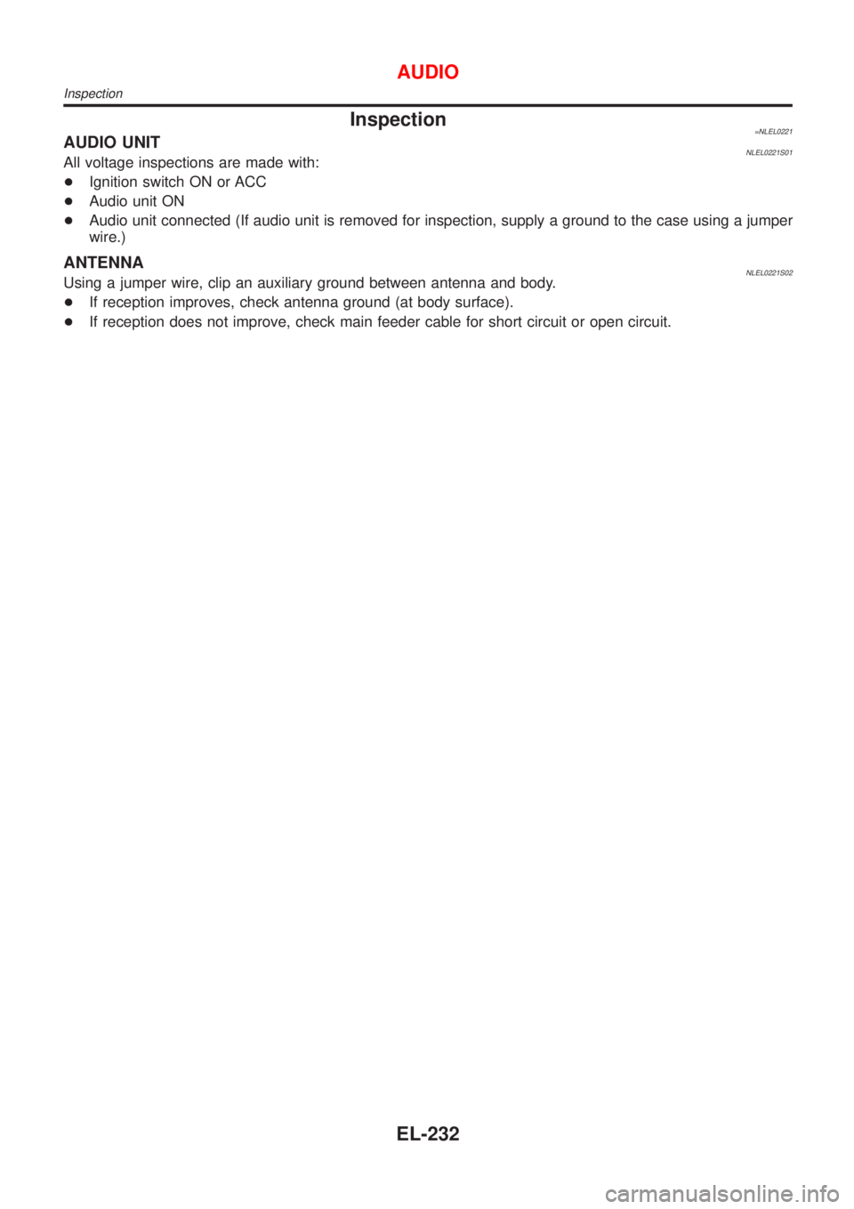
Inspection=NLEL0221AUDIO UNITNLEL0221S01All voltage inspections are made with:
+Ignition switch ON or ACC
+Audio unit ON
+Audio unit connected (If audio unit is removed for inspection, supply a ground to the case using a jumper
wire.)
ANTENNANLEL0221S02Using a jumper wire, clip an auxiliary ground between antenna and body.
+If reception improves, check antenna ground (at body surface).
+If reception does not improve, check main feeder cable for short circuit or open circuit.
AUDIO
Inspection
EL-232
Page 2256 of 3051
NLEL0311
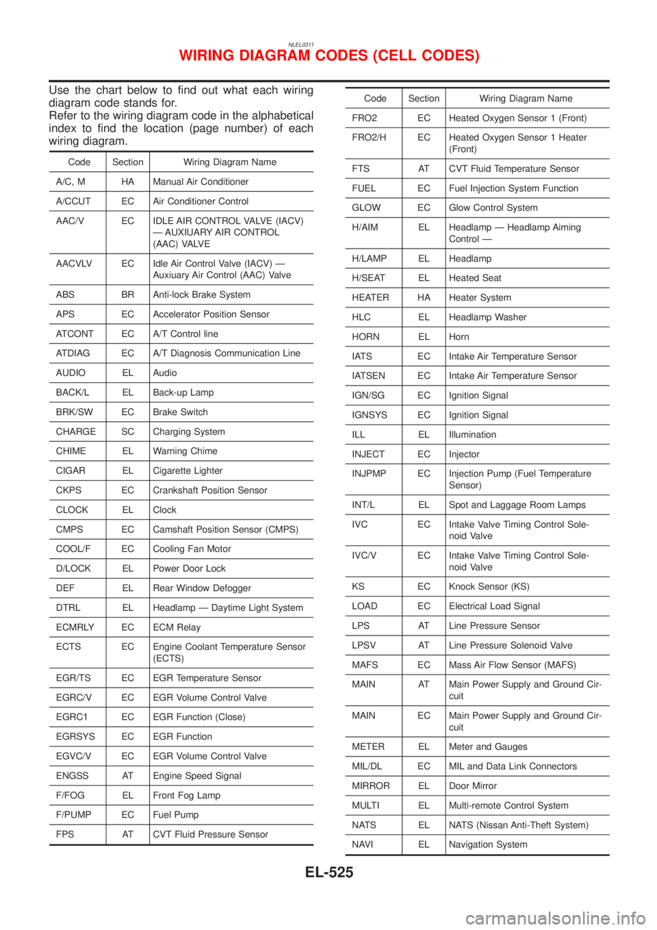
Use the chart below to find out what each wiring
diagram code stands for.
Refer to the wiring diagram code in the alphabetical
index to find the location (page number) of each
wiring diagram.
Code Section Wiring Diagram Name
A/C, M HA Manual Air Conditioner
A/CCUT EC Air Conditioner Control
AAC/V EC IDLE AIR CONTROL VALVE (IACV)
Ð AUXIUARY AIR CONTROL
(AAC) VALVE
AACVLV EC Idle Air Control Valve (IACV) Ð
Auxiuary Air Control (AAC) Valve
ABS BR Anti-lock Brake System
APS EC Accelerator Position Sensor
ATCONT EC A/T Control line
ATDIAG EC A/T Diagnosis Communication Line
AUDIO EL Audio
BACK/L EL Back-up Lamp
BRK/SW EC Brake Switch
CHARGE SC Charging System
CHIME EL Warning Chime
CIGAR EL Cigarette Lighter
CKPS EC Crankshaft Position Sensor
CLOCK EL Clock
CMPS EC Camshaft Position Sensor (CMPS)
COOL/F EC Cooling Fan Motor
D/LOCK EL Power Door Lock
DEF EL Rear Window Defogger
DTRL EL Headlamp Ð Daytime Light System
ECMRLY EC ECM Relay
ECTS EC Engine Coolant Temperature Sensor
(ECTS)
EGR/TS EC EGR Temperature Sensor
EGRC/V EC EGR Volume Control Valve
EGRC1 EC EGR Function (Close)
EGRSYS EC EGR Function
EGVC/V EC EGR Volume Control Valve
ENGSS AT Engine Speed Signal
F/FOG EL Front Fog Lamp
F/PUMP EC Fuel Pump
FPS AT CVT Fluid Pressure Sensor
Code Section Wiring Diagram Name
FRO2 EC Heated Oxygen Sensor 1 (Front)
FRO2/H EC Heated Oxygen Sensor 1 Heater
(Front)
FTS AT CVT Fluid Temperature Sensor
FUEL EC Fuel Injection System Function
GLOW EC Glow Control System
H/AIM EL Headlamp Ð Headlamp Aiming
Control Ð
H/LAMP EL Headlamp
H/SEAT EL Heated Seat
HEATER HA Heater System
HLC EL Headlamp Washer
HORN EL Horn
IATS EC Intake Air Temperature Sensor
IATSEN EC Intake Air Temperature Sensor
IGN/SG EC Ignition Signal
IGNSYS EC Ignition Signal
ILL EL Illumination
INJECT EC Injector
INJPMP EC Injection Pump (Fuel Temperature
Sensor)
INT/L EL Spot and Laggage Room Lamps
IVC EC Intake Valve Timing Control Sole-
noid Valve
IVC/V EC Intake Valve Timing Control Sole-
noid Valve
KS EC Knock Sensor (KS)
LOAD EC Electrical Load Signal
LPS AT Line Pressure Sensor
LPSV AT Line Pressure Solenoid Valve
MAFS EC Mass Air Flow Sensor (MAFS)
MAIN AT Main Power Supply and Ground Cir-
cuit
MAIN EC Main Power Supply and Ground Cir-
cuit
METER EL Meter and Gauges
MIL/DL EC MIL and Data Link Connectors
MIRROR EL Door Mirror
MULTI EL Multi-remote Control System
NATS EL NATS (Nissan Anti-Theft System)
NAVI EL Navigation System
WIRING DIAGRAM CODES (CELL CODES)
EL-525
Page 2476 of 3051
crankshaft position sensor (TDC sensor) from the assem-
bly.
+Always pay extra attention not to damage edge of crank-
shaft position sensor (TDC sensor) or ring gear teeth.
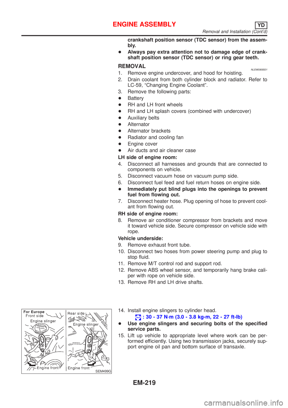
REMOVALNLEM0069S011. Remove engine undercover, and hood for hoisting.
2. Drain coolant from both cylinder block and radiator. Refer to
LC-59, ªChanging Engine Coolantº.
3. Remove the following parts:
+Battery
+RH and LH front wheels
+RH and LH splash covers (combined with undercover)
+Auxiliary belts
+Alternator
+Alternator brackets
+Radiator and cooling fan
+Engine cover
+Air ducts and air cleaner case
LH side of engine room:
4. Disconnect all harnesses and grounds that are connected to
components on vehicle.
5. Disconnect vacuum hose on vacuum pump side.
6. Disconnect fuel feed and fuel return hoses on engine side.
+Immediately put blind plugs into the openings to prevent
fuel from flowing out.
7. Disconnect heater hose. Plug opening of hose to prevent cool-
ant from flowing out.
RH side of engine room:
8. Remove air conditioner compressor from brackets and move
it toward vehicle side. Secure compressor on vehicle side with
rope.
Vehicle underside:
9. Remove exhaust front tube.
10. Disconnect two hoses from power steering pump and plug to
stop fluid.
11. Remove M/T control rod and support rod.
12. Remove ABS wheel sensor, and temporarily hang brake cali-
per with rope on vehicle side.
13. Remove RH and LH drive shafts.
SEM499G
14. Install engine slingers to cylinder head.
: 30 - 37 N´m (3.0 - 3.8 kg-m, 22 - 27 ft-lb)
+Use engine slingers and securing bolts of the specified
service parts.
15. Lift up vehicle to appropriate level where work can be per-
formed efficiently. Using two transmission jacks, securely sup-
port engine oil pan and bottom surface of transaxle.
ENGINE ASSEMBLYYD
Removal and Installation (Cont'd)
EM-219
Page 2480 of 3051
JEM193G
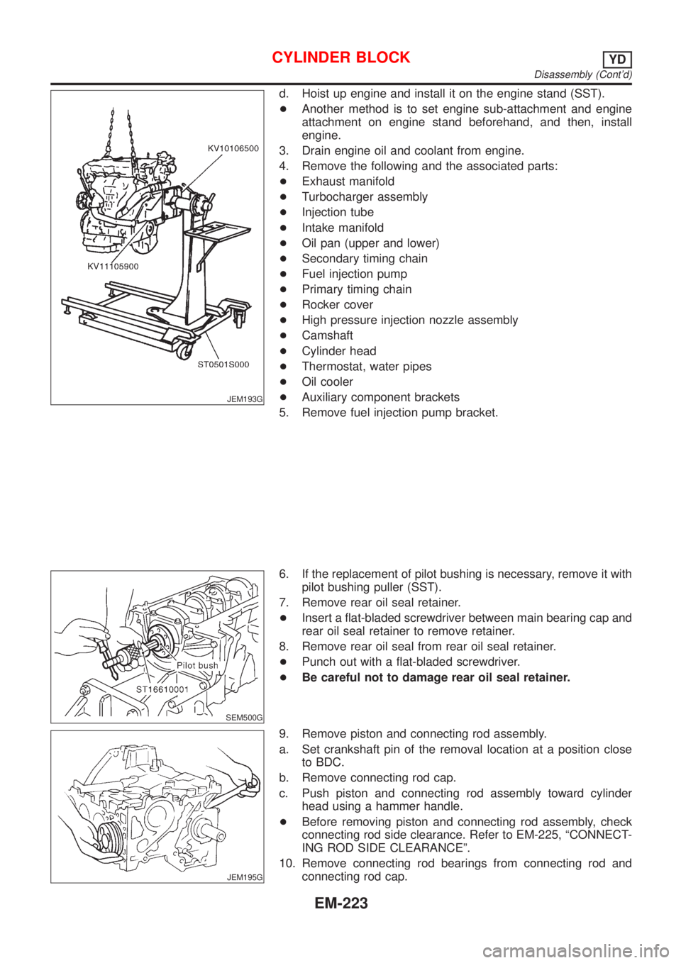
d. Hoist up engine and install it on the engine stand (SST).
+Another method is to set engine sub-attachment and engine
attachment on engine stand beforehand, and then, install
engine.
3. Drain engine oil and coolant from engine.
4. Remove the following and the associated parts:
+Exhaust manifold
+Turbocharger assembly
+Injection tube
+Intake manifold
+Oil pan (upper and lower)
+Secondary timing chain
+Fuel injection pump
+Primary timing chain
+Rocker cover
+High pressure injection nozzle assembly
+Camshaft
+Cylinder head
+Thermostat, water pipes
+Oil cooler
+Auxiliary component brackets
5. Remove fuel injection pump bracket.
SEM500G
6. If the replacement of pilot bushing is necessary, remove it with
pilot bushing puller (SST).
7. Remove rear oil seal retainer.
+Insert a flat-bladed screwdriver between main bearing cap and
rear oil seal retainer to remove retainer.
8. Remove rear oil seal from rear oil seal retainer.
+Punch out with a flat-bladed screwdriver.
+Be careful not to damage rear oil seal retainer.
JEM195G
9. Remove piston and connecting rod assembly.
a. Set crankshaft pin of the removal location at a position close
to BDC.
b. Remove connecting rod cap.
c. Push piston and connecting rod assembly toward cylinder
head using a hammer handle.
+Before removing piston and connecting rod assembly, check
connecting rod side clearance. Refer to EM-225, ªCONNECT-
ING ROD SIDE CLEARANCEº.
10. Remove connecting rod bearings from connecting rod and
connecting rod cap.
CYLINDER BLOCKYD
Disassembly (Cont'd)
EM-223
Page 2496 of 3051

JEM233G
16. Install rear oil seal retainer.
+Apply a continuous bead of specified liquid gasket (Refer to
EM-158, ªLiquid Gasket Application Procedureº.) on locations
shown in the figure.
JEM234G
17. Install pilot bushing.
+Force fit with the drift [approx. 19 mm (0.75 in) dia.].
SEM513G
18. Install fuel injection pump bracket.
+Install insulator according to the shape of the block, and secure
by placing the bracket against the insulator. (Not installed on
some models)
+Align the bracket with the dowel pins on the block to install.
+The two bolts used for dowel pins have a longer shanks than
the other two.
+Check the protruding distance of the dowel pin for fuel injec-
tion pump.
Standard: 13.0 - 15.0 mm (0.512 - 0.591 in)
19. Install parts to the engine in the reverse order of disassembly.
+Tighten bolts securing brackets of auxiliary components (A/C
compressor, alternator) to the specified torque.
: 57 - 65 N´m (5.8 - 6.7 kg-m, 42 - 48 ft-lb)
20. Remove engine from engine stand in the reverse order of
assembly.
21. Install flywheel.
+Holding ring gear with ring stopper (SST), tighten securing
bolts with TORX-socket (size: Q8 E20, Commercial Service
Tool).
+Tighten bolts uniformly in a crisscross manner.
SEM500G
REPLACEMENT OF PILOT BUSHINGNLEM0074S031. Remove pilot bushing using tool or suitable tool.
CYLINDER BLOCKYD
Assembly (Cont'd)
EM-239
Page 2588 of 3051

NEW TERMNEW ACRONYM /
ABBREVIATIONOLD TERM
Erasable programmable read only
memoryEPROM ***
Evaporative emission canister or Canister EVAP canister or Canister Canister
Evaporative emission canister purge con-
trol solenoid valveEVAP canister purge control solenoid
valveCanister control solenoid valve
Evaporative emission canister purge con-
trol valveEVAP canister purge control valve Canister purge cut valve
Evaporative emission canister vent control
valveEVAP canister vent control valve ***
Evaporative emission canister purge vol-
ume control valveEVAP canister purge volume control valve Canister purge control valve
Evaporative emission control system pres-
sure sensorEVAP control system pressure sensor ***
Evaportavie emission shut valve EVAP shut valve Shutoff valve
Evaporative emission system EVAP system Evaporative emission control system
Exhaust gas recirculation valve EGR valve EGR valve
Exhaust gas recirculation control-BPT
valveEGRC-BPT valve BPT valve
Exhaust gas recirculation control-solenoid
valveEGRC-solenoid valve EGR control solenoid valve
Exhaust gas recirculation temperature
sensorEGR temperature sensor Exhaust gas temperature sensor
Flash electrically erasable programmable
read only memoryFEEPROM ***
Flash erasable programmable read only
memoryFEPROM ***
Flexible fuel sensor FFS ***
Heated oxygen sensor HO2S Exhaust gas sensor
Idle air control system IAC system Idle speed control
Idle air control valve-air regulator IACV-air regulator Air regulator
Idle air control valve-auxiliary air control
valveIACV-AAC valve Auxiliary air control (AAC) valve
Idle air control valve-FICD solenoid valve IACV-FICD solenoid valve FICD solenoid valve
Idle air control valve-idle up control sole-
noid valveIACV-idle up control solenoid valve Idle up control solenoid valve
Idle speed control-FI pot ISC-FI pot FI pot
Idle speed control system ISC system ***
Ignition control module ICM ***
Indirect fuel injection system IFI system ***
Intake air temperature sensor IATS sensor Air temperature sensor
Knock *** Detonation
Knock sensor KS Detonation sensor
Malfunction indicator lamp MI Check engine light
ISO 15031–2 TERMINOLOGY LIST
ISO 15031–2 Terminology List (Cont’d)
GI-49
Page 2592 of 3051
HEATER &
AIR CONDITIONER
SECTION
HA
CONTENTS
PRECAUTIONS...............................................................2
Supplemental Restraint System (SRS)″AIR
BAG″and″SEAT BELT PRE-TENSIONER″...............2
Precautions for Working with HFC-134a (R-134a) .....2
General Refrigerant Precautions .................................2
Precautions for Refrigerant Connection ......................3
Precautions for Servicing Compressor ........................5
Precautions for Service Equipment .............................6
Wiring Diagrams and Trouble Diagnosis .....................8
PREPARATION...............................................................9
Special Service Tools ..................................................9
HFC-134a (R-134a) Service Tools and
Equipment ..................................................................10
DESCRIPTION...............................................................12
Refrigeration System .................................................12
CSV613 Variable Displacement Compressor............13
Component Layout ....................................................17
Control Operation ......................................................18
Discharge Air Flow.....................................................19
System Description ....................................................20
TROUBLE DIAGNOSES................................................21
Component Location..................................................21
Wiring Diagram - Heater............................................23
Circuit Diagram - Air Conditioner...............................26
Wiring Diagram - A/C, M - .........................................27
How to Perform Trouble Diagnoses for Quick
and Accurate Repair ..................................................40
Operational Check .....................................................41Intake Door ................................................................43
Mode Door .................................................................47
Air Mix Door ...............................................................49
Max Hot Door (For Scandinavia and Cold Spec
Models) ......................................................................51
Blower Motor..............................................................55
Magnet Clutch............................................................62
Insufficient Cooling ....................................................75
Insufficient Heating ....................................................83
Noise ..........................................................................84
SERVICE PROCEDURE................................................85
HFC-134a (R-134a) Service Procedure ....................85
Maintenance of Lubricant Quantity in
Compressor ...............................................................87
Compressor ...............................................................90
Compressor Clutch - CSV613 (CALSONIC
make) .........................................................................92
Heater & Cooling Unit (Heater Core) ........................95
A/C Evaporator ..........................................................96
Blower Unit ................................................................97
Refrigerant Lines .......................................................98
Belt ...........................................................................102
Idle Air Control Valve (IACV) - Auxiliary Air
Control (AAC) Valve ................................................103
Ventilation Air Filter ..................................................103
SERVICE DATA AND SPECIFICATIONS (SDS).......104
Manual .....................................................................104
Page 2694 of 3051
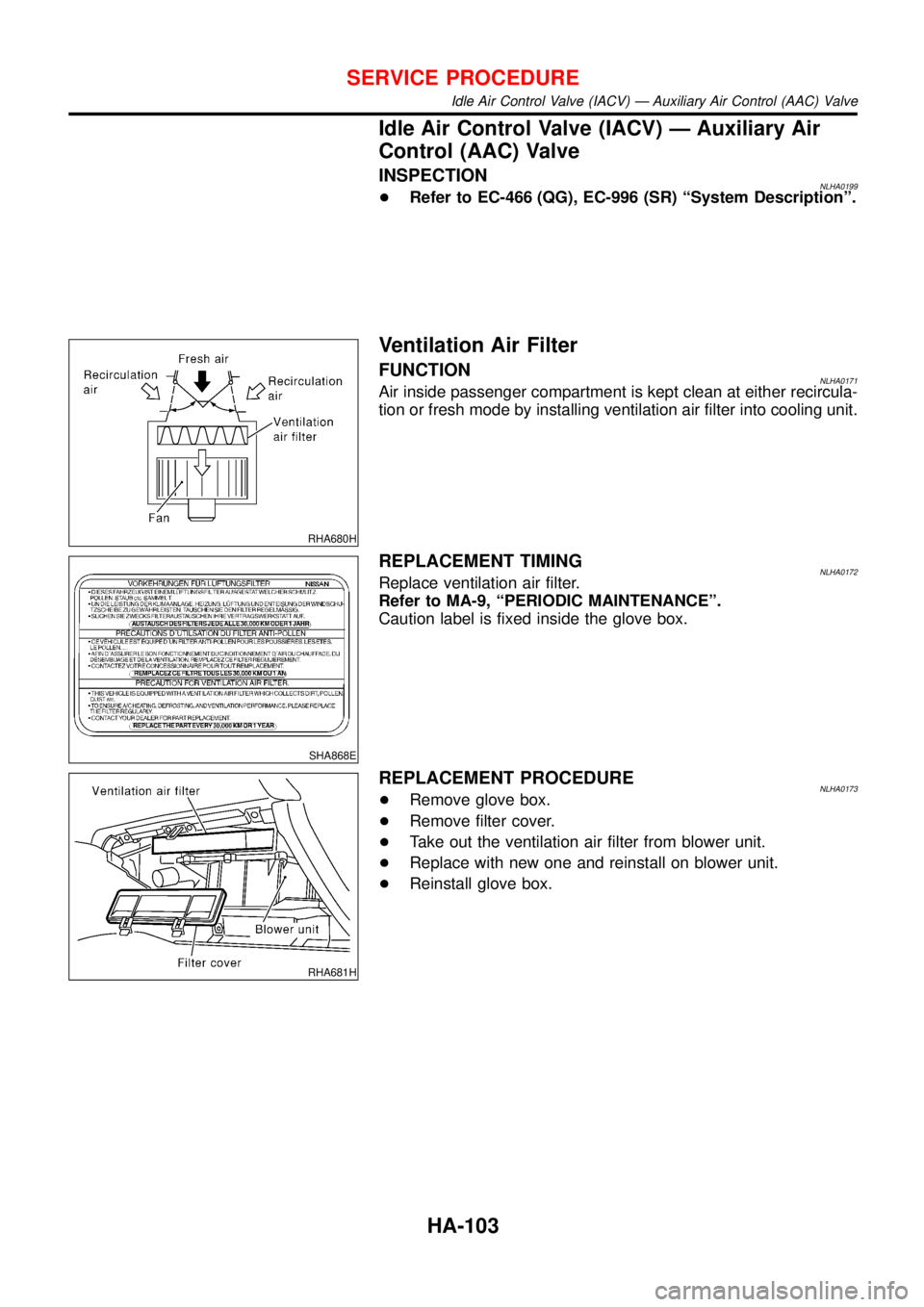
IdleAi rContro lV alv e(IACV )— Auxiliar yAir
RHA680H
SHA868E
RHA681H
Idl eAi rContro lV alv e(IACV )— Auxiliar yAi rContro l(AAC )Valve