2001 NISSAN ALMERA TINO cooling
[x] Cancel search: coolingPage 954 of 3051
JEF147Y
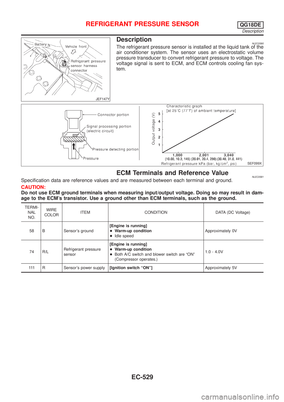
DescriptionNLEC0580The refrigerant pressure sensor is installed at the liquid tank of the
air conditioner system. The sensor uses an electrostatic volume
pressure transducer to convert refrigerant pressure to voltage. The
voltage signal is sent to ECM, and ECM controls cooling fan sys-
tem.
SEF099X
ECM Terminals and Reference ValueNLEC0581Specification data are reference values and are measured between each terminal and ground.
CAUTION:
Do not use ECM ground terminals when measuring input/output voltage. Doing so may result in dam-
age to the ECM's transistor. Use a ground other than ECM terminals, such as the ground.
TERMI-
NAL
NO.WIRE
COLORITEM CONDITION DATA (DC Voltage)
58 B Sensor's ground[Engine is running]
+Warm-up condition
+Idle speedApproximately 0V
74 R/LRefrigerant pressure
sensor[Engine is running]
+Warm-up condition
+Both A/C switch and blower switch are ªONº
(Compressor operates.)1.0 - 4.0V
111 R Sensor's power supply[Ignition switch ªONº]Approximately 5V
REFRIGERANT PRESSURE SENSORQG18DE
Description
EC-529
Page 993 of 3051
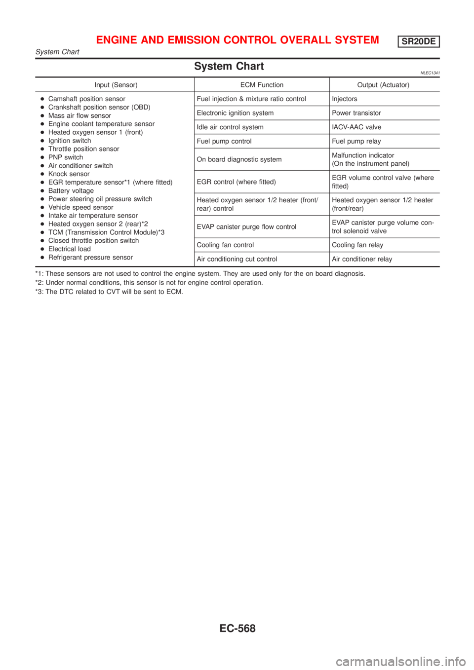
System ChartNLEC1341
Input (Sensor) ECM Function Output (Actuator)
+Camshaft position sensor
+Crankshaft position sensor (OBD)
+Mass air flow sensor
+Engine coolant temperature sensor
+Heated oxygen sensor 1 (front)
+Ignition switch
+Throttle position sensor
+PNP switch
+Air conditioner switch
+Knock sensor
+EGR temperature sensor*1 (where fitted)
+Battery voltage
+Power steering oil pressure switch
+Vehicle speed sensor
+Intake air temperature sensor
+Heated oxygen sensor 2 (rear)*2
+TCM (Transmission Control Module)*3
+Closed throttle position switch
+Electrical load
+Refrigerant pressure sensorFuel injection & mixture ratio control Injectors
Electronic ignition system Power transistor
Idle air control system IACV-AAC valve
Fuel pump control Fuel pump relay
On board diagnostic systemMalfunction indicator
(On the instrument panel)
EGR control (where fitted)EGR volume control valve (where
fitted)
Heated oxygen sensor 1/2 heater (front/
rear) controlHeated oxygen sensor 1/2 heater
(front/rear)
EVAP canister purge flow controlEVAP canister purge volume con-
trol solenoid valve
Cooling fan control Cooling fan relay
Air conditioning cut control Air conditioner relay
*1: These sensors are not used to control the engine system. They are used only for the on board diagnosis.
*2: Under normal conditions, this sensor is not for engine control operation.
*3: The DTC related to CVT will be sent to ECM.
ENGINE AND EMISSION CONTROL OVERALL SYSTEMSR20DE
System Chart
EC-568
Page 1006 of 3051
SEF217Z
SEF454Y
SEF455Y
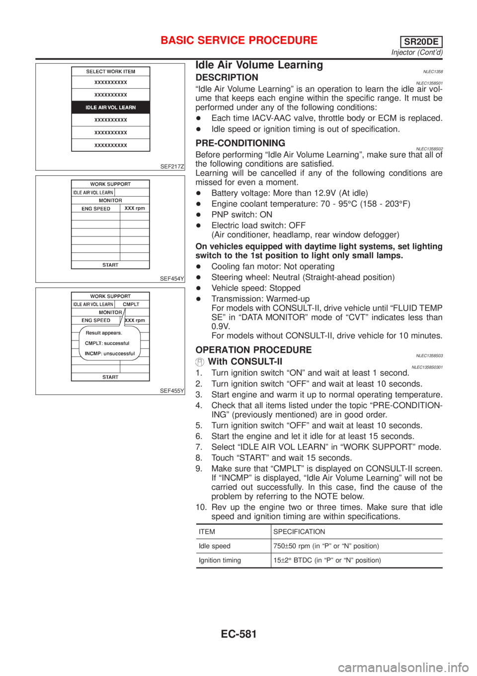
Idle Air Volume LearningNLEC1358DESCRIPTIONNLEC1358S01ªIdle Air Volume Learningº is an operation to learn the idle air vol-
ume that keeps each engine within the specific range. It must be
performed under any of the following conditions:
+Each time IACV-AAC valve, throttle body or ECM is replaced.
+Idle speed or ignition timing is out of specification.
PRE-CONDITIONINGNLEC1358S02Before performing ªIdle Air Volume Learningº, make sure that all of
the following conditions are satisfied.
Learning will be cancelled if any of the following conditions are
missed for even a moment.
+Battery voltage: More than 12.9V (At idle)
+Engine coolant temperature: 70 - 95ÉC (158 - 203ÉF)
+PNP switch: ON
+Electric load switch: OFF
(Air conditioner, headlamp, rear window defogger)
On vehicles equipped with daytime light systems, set lighting
switch to the 1st position to light only small lamps.
+Cooling fan motor: Not operating
+Steering wheel: Neutral (Straight-ahead position)
+Vehicle speed: Stopped
+Transmission: Warmed-up
For models with CONSULT-II, drive vehicle until ªFLUID TEMP
SEº in ªDATA MONITORº mode of ªCVTº indicates less than
0.9V.
For models without CONSULT-II, drive vehicle for 10 minutes.
OPERATION PROCEDURENLEC1358S03With CONSULT-IINLEC1358S03011. Turn ignition switch ªONº and wait at least 1 second.
2. Turn ignition switch ªOFFº and wait at least 10 seconds.
3. Start engine and warm it up to normal operating temperature.
4. Check that all items listed under the topic ªPRE-CONDITION-
INGº (previously mentioned) are in good order.
5. Turn ignition switch ªOFFº and wait at least 10 seconds.
6. Start the engine and let it idle for at least 15 seconds.
7. Select ªIDLE AIR VOL LEARNº in ªWORK SUPPORTº mode.
8. Touch ªSTARTº and wait 15 seconds.
9. Make sure that ªCMPLTº is displayed on CONSULT-II screen.
If ªINCMPº is displayed, ªIdle Air Volume Learningº will not be
carried out successfully. In this case, find the cause of the
problem by referring to the NOTE below.
10. Rev up the engine two or three times. Make sure that idle
speed and ignition timing are within specifications.
ITEM SPECIFICATION
Idle speed 750±50 rpm (in ªPº or ªNº position)
Ignition timing 15±2É BTDC (in ªPº or ªNº position)
BASIC SERVICE PROCEDURESR20DE
Injector (Cont'd)
EC-581
Page 1034 of 3051
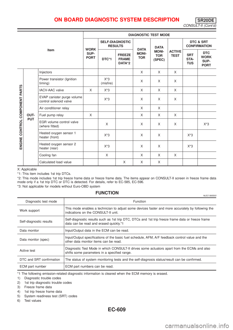
ItemDIAGNOSTIC TEST MODE
WORK
SUP-
PORTSELF-DIAGNOSTIC
RESULTS
D ATA
MONI-
TORD ATA
MONI-
TOR
(SPEC)ACTIVE
TESTDTC & SRT
CONFIRMATION
DTC*1FREEZE
FRAME
DATA*2SRT
STA-
TUSDTC
WORK
SUP-
PORT
ENGINE CONTROL COMPONENT PARTS
OUT-
PUTInjectors X X X
Power transistor (Ignition
timing)X*3
(misfire)XXX
IACV-AAC valve X X*3 X X X
EVAP canister purge volume
control solenoid valveX*3 X X X
Air conditioner relay X X
Fuel pump relay X X X X
EGR volume control valve
(where fitted)X X X X X*3
Heated oxygen sensor 1
heater (front)X*3 X X X*3
Heated oxygen sensor 2
heater (rear)X*3 X X X*3
Cooling fan X X X X
Calculated load value X X X
X: Applicable
*1: This item includes 1st trip DTCs.
*2: This mode includes 1st trip freeze frame data or freeze frame data. The items appear on CONSULT-II screen in freeze frame data
mode only if a 1st trip DTC or DTC is detected. For details, refer to EC-585, EC-596.
*3: Not applicable for models without Euro-OBD system
FUNCTIONNLEC1365S03
Diagnostic test mode Function
Work supportThis mode enables a technician to adjust some devices faster and more accurately by following the
indications on the CONSULT-II unit.
Self-diagnostic resultsSelf-diagnostic results such as 1st trip DTC, DTCs and 1st trip freeze frame data or freeze frame
data can be read and erased quickly.*1
Data monitor Input/Output data in the ECM can be read.
Data monitor (spec)Input/Output specifications of the basic fuel schedule, AFM, A/F feedback control value and the
other data monitor items can be read.
Active testDiagnostic Test Mode in which CONSULT-II drives some actuators apart from the ECMs and also
shifts some parameters in a specified range.
DTC and SRT confirmation The status of system monitoring tests and the self-diagnosis status/result can be confirmed.
ECM part number ECM part numbers can be read.
*1 The following emission-related diagnostic information is cleared when the ECM memory is erased.
1) Diagnostic trouble codes
2) 1st trip diagnostic trouble codes
3) Freeze frame data
4) 1st trip freeze frame data
5) System readiness test (SRT) codes
6) Test values
ON BOARD DIAGNOSTIC SYSTEM DESCRIPTIONSR20DE
CONSULT-II (Cont'd)
EC-609
Page 1038 of 3051
![NISSAN ALMERA TINO 2001 Service Repair Manual Monitored item [Unit]ECM
input
signalsMain
signalsDescription Remarks
EGR VOL CON/V
[step] (where fitted)j+Indicates the EGR volume control valve com-
puted by the ECM according to the input sig-
nals NISSAN ALMERA TINO 2001 Service Repair Manual Monitored item [Unit]ECM
input
signalsMain
signalsDescription Remarks
EGR VOL CON/V
[step] (where fitted)j+Indicates the EGR volume control valve com-
puted by the ECM according to the input sig-
nals](/manual-img/5/57352/w960_57352-1037.png)
Monitored item [Unit]ECM
input
signalsMain
signalsDescription Remarks
EGR VOL CON/V
[step] (where fitted)j+Indicates the EGR volume control valve com-
puted by the ECM according to the input sig-
nals.
+The opening becomes larger as the value
increases.
AIR COND RLY
[ON/OFF]j+Indicates the air conditioner relay control con-
dition determined by ECM according to the
input signals.
FUEL PUMP RLY
[ON/OFF]j+Indicates the fuel pump relay control condi-
tion determined by ECM according to the
input signals.
COOLING FAN
[HIGH/LOW/OFF]+Indicates the control condition of the cooling
fan (determined by ECM according to the
input signal).
HIGH ... High speed operation
LOW ... Low speed operation
OFF ... Stop
HO2S1 HTR (B1)
[ON/OFF]+Indicates [ON/OFF] condition of heated oxy-
gen sensor 1 heater (front) determined by
ECM according to the input signals.
HO2S2 HTR (B1)
[ON/OFF]+Indicates [ON/OFF] condition of heated oxy-
gen sensor 2 heater (rear) determined by
ECM according to the input signals.
IDL A/V LEARN+Display the condition of idle air volume learn-
ing
YET ... Idle air volume learning has not been
performed yet.
CMPLT ... Idle air volume learning has
already been performed successfully.
INCMP ... Idle air volume learning has not
been performed successfully.
TRVL AFTER MIL
[km] or [Mile]+Distance traveled while MI is activated
VOLTAGE [V]+Voltage measured by the voltage probe.
PULSE
[msec] or [Hz] or [%]+Pulse width, frequency or duty cycle mea-
sured by the pulse probe.+Only ª#º is displayed if item is
unable to be measured.
+Figures with ª#ºs are temporary
ones. They are the same figures as
an actual piece of data which was
just previously measured.
NOTE:
Any monitored item that does not match the vehicle being diagnosed is deleted from the display automatically.
DATA MONITOR (SPEC) MODENLEC1365S07
Monitored item [Unit]ECM
input
signalsMain
signalsDescription Remarks
MAS A/F SE-B1 [V]jj+The signal voltage of the mass air flow sen-
sor specification is displayed.+When the engine is running, specifi-
cation range is indicated.
B/FUEL SCHDL
[msec]+ªBase fuel scheduleº indicates the fuel injec-
tion pulse width programmed into ECM, prior
to any learned on board correction.+When the engine is running, specifi-
cation range is indicated.
ON BOARD DIAGNOSTIC SYSTEM DESCRIPTIONSR20DE
CONSULT-II (Cont'd)
EC-613
Page 1039 of 3051
![NISSAN ALMERA TINO 2001 Service Repair Manual Monitored item [Unit]ECM
input
signalsMain
signalsDescription Remarks
A/F ALPHA-B1 [%]j+Indicates the mean value of the air-fuel ratio
feedback correction factor per cycle.+When the engine is running, NISSAN ALMERA TINO 2001 Service Repair Manual Monitored item [Unit]ECM
input
signalsMain
signalsDescription Remarks
A/F ALPHA-B1 [%]j+Indicates the mean value of the air-fuel ratio
feedback correction factor per cycle.+When the engine is running,](/manual-img/5/57352/w960_57352-1038.png)
Monitored item [Unit]ECM
input
signalsMain
signalsDescription Remarks
A/F ALPHA-B1 [%]j+Indicates the mean value of the air-fuel ratio
feedback correction factor per cycle.+When the engine is running, specifi-
cation range is indicated.
+This data also includes the data for
the air-fuel ratio learning control.
NOTE:
Any monitored item that does not match the vehicle being diagnosed is deleted from the display automatically.
ACTIVE TEST MODENLEC1365S08
TEST ITEM CONDITION JUDGEMENT CHECK ITEM (REMEDY)
FUEL INJEC-
TION+Engine: Return to the original
trouble condition
+Change the amount of fuel injec-
tion using CONSULT-II.If trouble symptom disappears, see
CHECK ITEM.+Harness and connector
+Fuel injectors
+Heated oxygen sensor 1 (front)
IGNITION TIM-
ING+Engine: Return to the original
trouble condition
+Timing light: Set
+Retard the ignition timing using
CONSULT-II.If trouble symptom disappears, see
CHECK ITEM.+Adjust initial ignition timing.
IACV-AAC/V
OPENING+Engine: After warming up, idle
the engine.
+Change the IACV-AAC valve
opening steps using CONSULT-
II.Engine speed changes according
to the opening steps.+Harness and connector
+IACV-AAC valve
POWER BAL-
ANCE+Engine: After warming up, idle
the engine.
+Air conditioner switch ªOFFº
+Shift lever ªNº
+Cut off each injector signal one
at a time using CONSULT-II.Engine runs rough or dies.+Harness and connector
+Compression
+Injectors
+Power transistor
+Spark plugs
+Ignition coil
+Ignition wires
COOLING FAN+Ignition switch: ON
+Turn the cooling fan ªHIGHº,
ªLOWº and ªOFFº using CON-
SULT-II.Cooling fan moves at high speed or
low speed and stops.+Harness and connector
+Cooling fan motors
+Cooling fan relays
ENG COOLANT
TEMP+Engine: Return to the original
trouble condition
+Change the engine coolant tem-
perature indication using CON-
SULT-II.If trouble symptom disappears, see
CHECK ITEM.+Harness and connector
+Engine coolant temperature sen-
sor
+Fuel injectors
FUEL PUMP
RELAY+Ignition switch: ON
(Engine stopped)
+Turn the fuel pump relay ªONº
and ªOFFº using CONSULT-II
and listen to operating sound.Fuel pump relay makes the operat-
ing sound.+Harness and connector
+Fuel pump relay
EGR VOL
CONT/V
(where fitted)+Engine: After warming up, idle
the engine.
+Change the EGR volume control
valve opening step using CON-
SULT-II.EGR volume control valve maks an
operating sound.+Harness and connector
+EGR volume control valve
ON BOARD DIAGNOSTIC SYSTEM DESCRIPTIONSR20DE
CONSULT-II (Cont'd)
EC-614
Page 1071 of 3051
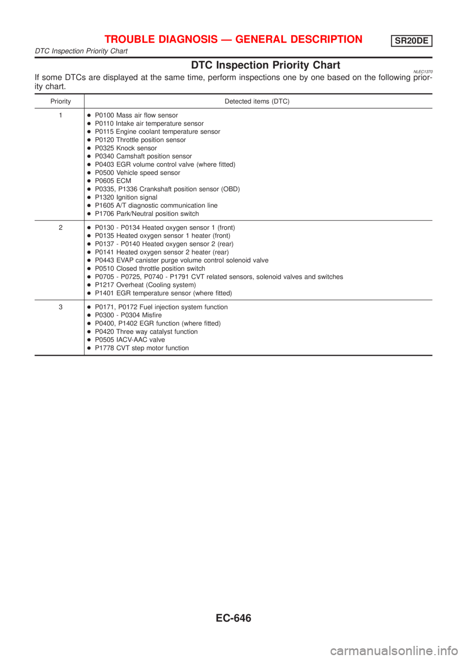
DTC Inspection Priority ChartNLEC1370If some DTCs are displayed at the same time, perform inspections one by one based on the following prior-
ity chart.
Priority Detected items (DTC)
1+P0100 Mass air flow sensor
+P0110 Intake air temperature sensor
+P0115 Engine coolant temperature sensor
+P0120 Throttle position sensor
+P0325 Knock sensor
+P0340 Camshaft position sensor
+P0403 EGR volume control valve (where fitted)
+P0500 Vehicle speed sensor
+P0605 ECM
+P0335, P1336 Crankshaft position sensor (OBD)
+P1320 Ignition signal
+P1605 A/T diagnostic communication line
+P1706 Park/Neutral position switch
2+P0130 - P0134 Heated oxygen sensor 1 (front)
+P0135 Heated oxygen sensor 1 heater (front)
+P0137 - P0140 Heated oxygen sensor 2 (rear)
+P0141 Heated oxygen sensor 2 heater (rear)
+P0443 EVAP canister purge volume control solenoid valve
+P0510 Closed throttle position switch
+P0705 - P0725, P0740 - P1791 CVT related sensors, solenoid valves and switches
+P1217 Overheat (Cooling system)
+P1401 EGR temperature sensor (where fitted)
3+P0171, P0172 Fuel injection system function
+P0300 - P0304 Misfire
+P0400, P1402 EGR function (where fitted)
+P0420 Three way catalyst function
+P0505 IACV-AAC valve
+P1778 CVT step motor function
TROUBLE DIAGNOSIS Ð GENERAL DESCRIPTIONSR20DE
DTC Inspection Priority Chart
EC-646
Page 1076 of 3051
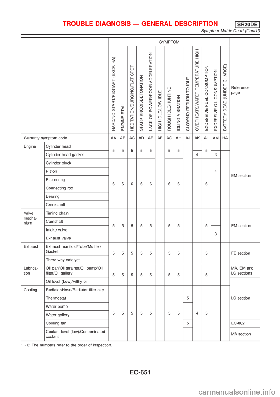
SYMPTOM
Reference
page
HARD/NO START/RESTART (EXCP. HA)
ENGINE STALL
HESITATION/SURGING/FLAT SPOT
SPARK KNOCK/DETONATION
LACK OF POWER/POOR ACCELERATION
HIGH IDLE/LOW IDLE
ROUGH IDLE/HUNTING
IDLING VIBRATION
SLOW/NO RETURN TO IDLE
OVERHEATS/WATER TEMPERATURE HIGH
EXCESSIVE FUEL CONSUMPTION
EXCESSIVE OIL CONSUMPTION
BATTERY DEAD (UNDER CHARGE)
Warranty symptom code AA AB AC AD AE AF AG AH AJ AK AL AM HA
Engine Cylinder head
55555 55 5
EM section Cylinder head gasket 4 3
Cylinder block
66666 66 64 Piston
Piston ring
Connecting rod
Bearing
Crankshaft
Valve
mecha-
nismTiming chain
55555 55 5 EMsection Camshaft
Intake valve
3
Exhaust valve
Exhaust Exhaust manifold/Tube/Muffler/
Gasket
55555 55 5 FEsection
Three way catalyst
Lubrica-
tionOil pan/Oil strainer/Oil pump/Oil
filter/Oil gallery
55555 55 5MA, EM and
LC sections
Oil level (Low)/Filthy oil
LC section Cooling Radiator/Hose/Radiator filler cap
55555 55 45 Thermostat 5
Water pump
Water gallery
Cooling fan 5 EC-882
Coolant level (low)/Contaminated
coolantMA section
1 - 6: The numbers refer to the order of inspection.
TROUBLE DIAGNOSIS Ð GENERAL DESCRIPTIONSR20DE
Symptom Matrix Chart (Cont'd)
EC-651