Page 586 of 3051
SEF206T
Component DescriptionNLEC0066MODELS WITH INTAKE AIR TEMPERATURE SENSOR
ON INTAKE AIR DUCT
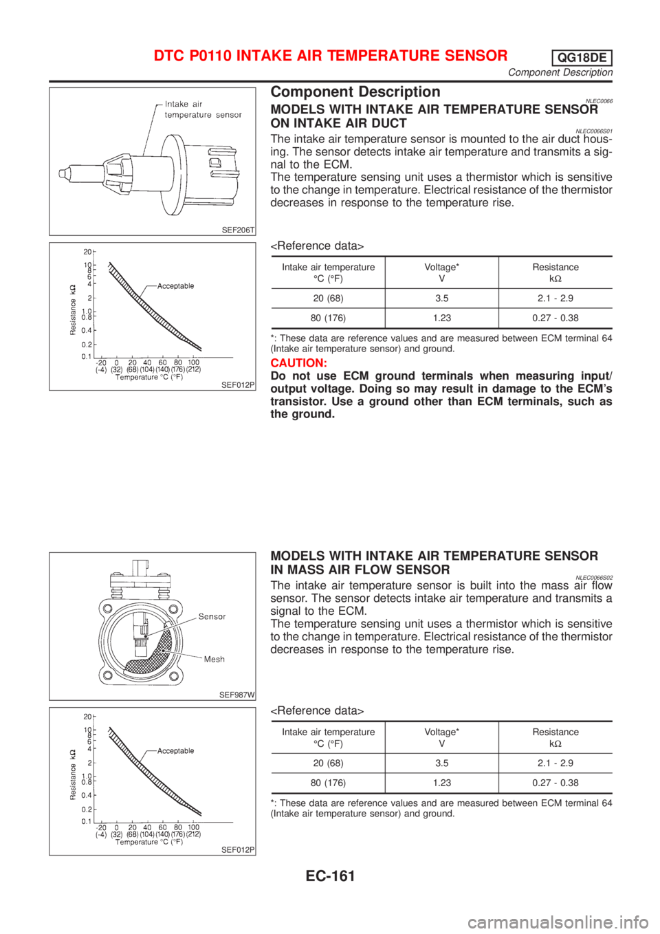
NLEC0066S01The intake air temperature sensor is mounted to the air duct hous-
ing. The sensor detects intake air temperature and transmits a sig-
nal to the ECM.
The temperature sensing unit uses a thermistor which is sensitive
to the change in temperature. Electrical resistance of the thermistor
decreases in response to the temperature rise.
SEF012P
Intake air temperature
ÉC (ÉF)Voltage*
VResistance
kW
20 (68) 3.5 2.1 - 2.9
80 (176) 1.23 0.27 - 0.38
*: These data are reference values and are measured between ECM terminal 64
(Intake air temperature sensor) and ground.
CAUTION:
Do not use ECM ground terminals when measuring input/
output voltage. Doing so may result in damage to the ECM's
transistor. Use a ground other than ECM terminals, such as
the ground.
SEF987W
MODELS WITH INTAKE AIR TEMPERATURE SENSOR
IN MASS AIR FLOW SENSOR
NLEC0066S02The intake air temperature sensor is built into the mass air flow
sensor. The sensor detects intake air temperature and transmits a
signal to the ECM.
The temperature sensing unit uses a thermistor which is sensitive
to the change in temperature. Electrical resistance of the thermistor
decreases in response to the temperature rise.
SEF012P
Intake air temperature
ÉC (ÉF)Voltage*
VResistance
kW
20 (68) 3.5 2.1 - 2.9
80 (176) 1.23 0.27 - 0.38
*: These data are reference values and are measured between ECM terminal 64
(Intake air temperature sensor) and ground.
DTC P0110 INTAKE AIR TEMPERATURE SENSORQG18DE
Component Description
EC-161
Page 600 of 3051
Component DescriptionNLEC0079NOTE:
If DTC P0120 (0120) is displayed with DTC P0510 (0510), first perform trouble diagnosis for DTC P0510,
EC-352.
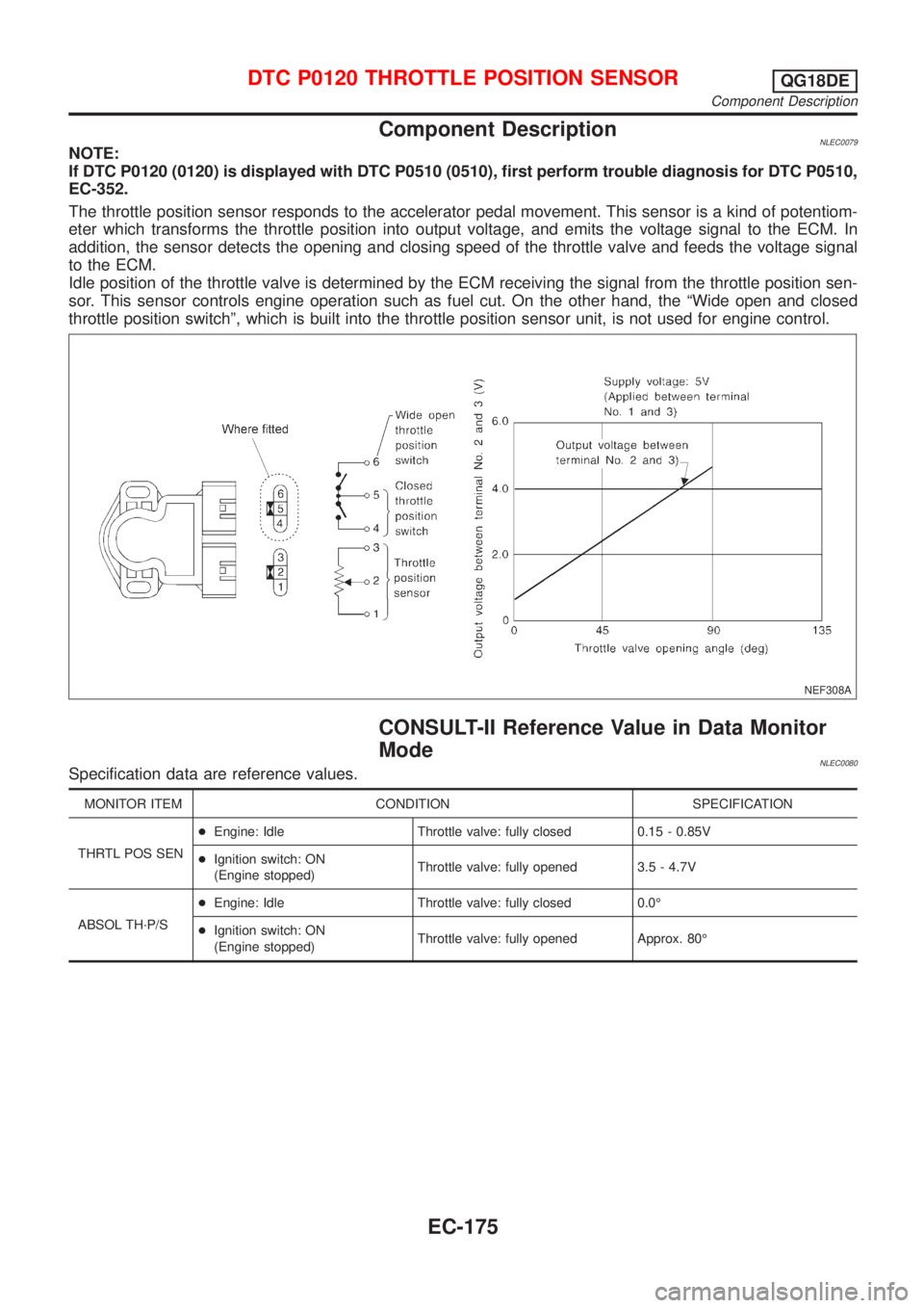
The throttle position sensor responds to the accelerator pedal movement. This sensor is a kind of potentiom-
eter which transforms the throttle position into output voltage, and emits the voltage signal to the ECM. In
addition, the sensor detects the opening and closing speed of the throttle valve and feeds the voltage signal
to the ECM.
Idle position of the throttle valve is determined by the ECM receiving the signal from the throttle position sen-
sor. This sensor controls engine operation such as fuel cut. On the other hand, the ªWide open and closed
throttle position switchº, which is built into the throttle position sensor unit, is not used for engine control.
NEF308A
CONSULT-II Reference Value in Data Monitor
Mode
NLEC0080Specification data are reference values.
MONITOR ITEM CONDITION SPECIFICATION
THRTL POS SEN+Engine: Idle Throttle valve: fully closed 0.15 - 0.85V
+Ignition switch: ON
(Engine stopped)Throttle valve: fully opened 3.5 - 4.7V
ABSOL TH´P/S+Engine: Idle Throttle valve: fully closed 0.0É
+Ignition switch: ON
(Engine stopped)Throttle valve: fully opened Approx. 80É
DTC P0120 THROTTLE POSITION SENSORQG18DE
Component Description
EC-175
Page 629 of 3051
SEF463R
SEF288D
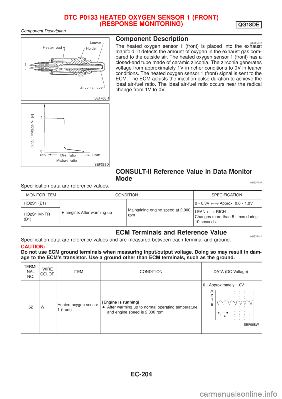
Component DescriptionNLEC0119The heated oxygen sensor 1 (front) is placed into the exhaust
manifold. It detects the amount of oxygen in the exhaust gas com-
pared to the outside air. The heated oxygen sensor 1 (front) has a
closed-end tube made of ceramic zirconia. The zirconia generates
voltage from approximately 1V in richer conditions to 0V in leaner
conditions. The heated oxygen sensor 1 (front) signal is sent to the
ECM. The ECM adjusts the injection pulse duration to achieve the
ideal air-fuel ratio. The ideal air-fuel ratio occurs near the radical
change from 1V to 0V.
CONSULT-II Reference Value in Data Monitor
Mode
NLEC0120Specification data are reference values.
MONITOR ITEM CONDITION SPECIFICATION
HO2S1 (B1)
+Engine: After warming upMaintaining engine speed at 2,000
rpm0 - 0.3V¨Approx. 0.6 - 1.0V
HO2S1 MNTR
(B1)LEAN¨RICH
Changes more than 5 times during
10 seconds.
ECM Terminals and Reference ValueNLEC0121Specification data are reference values and are measured between each terminal and ground.
CAUTION:
Do not use ECM ground terminals when measuring input/output voltage. Doing so may result in dam-
age to the ECM's transistor. Use a ground other than ECM terminals, such as the ground.
TERMI-
NAL
NO.WIRE
COLORITEM CONDITION DATA (DC Voltage)
62 WHeated oxygen sensor
1 (front)[Engine is running]
+After warming up to normal operating temperature
and engine speed is 2,000 rpm0 - Approximately 1.0V
SEF008W
DTC P0133 HEATED OXYGEN SENSOR 1 (FRONT)
(RESPONSE MONITORING)
QG18DE
Component Description
EC-204
Page 630 of 3051
SEF010V
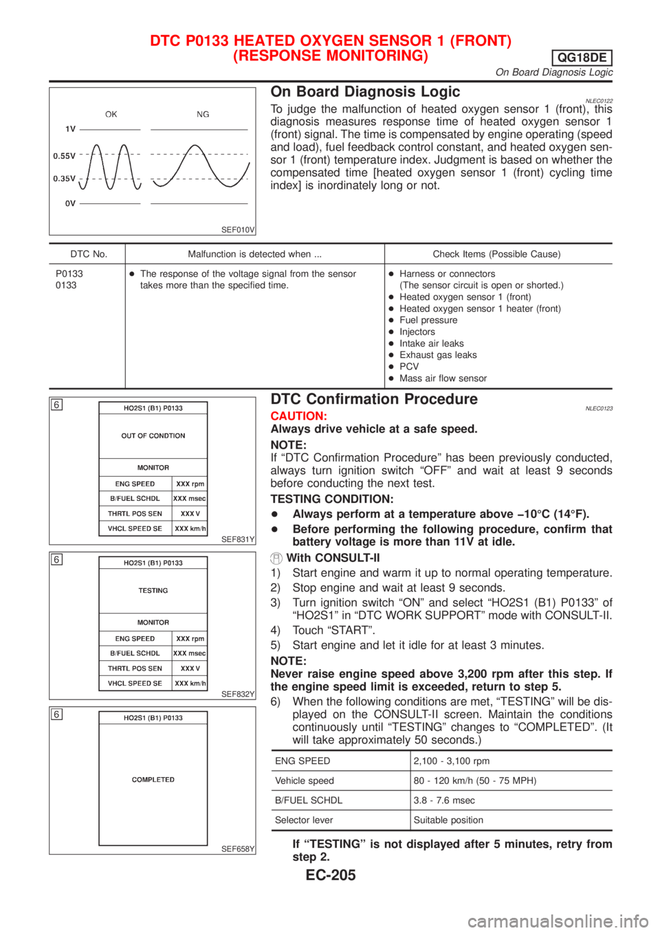
On Board Diagnosis LogicNLEC0122To judge the malfunction of heated oxygen sensor 1 (front), this
diagnosis measures response time of heated oxygen sensor 1
(front) signal. The time is compensated by engine operating (speed
and load), fuel feedback control constant, and heated oxygen sen-
sor 1 (front) temperature index. Judgment is based on whether the
compensated time [heated oxygen sensor 1 (front) cycling time
index] is inordinately long or not.
DTC No. Malfunction is detected when ... Check Items (Possible Cause)
P0133
0133+The response of the voltage signal from the sensor
takes more than the specified time.+Harness or connectors
(The sensor circuit is open or shorted.)
+Heated oxygen sensor 1 (front)
+Heated oxygen sensor 1 heater (front)
+Fuel pressure
+Injectors
+Intake air leaks
+Exhaust gas leaks
+PCV
+Mass air flow sensor
SEF831Y
SEF832Y
SEF658Y
DTC Confirmation ProcedureNLEC0123CAUTION:
Always drive vehicle at a safe speed.
NOTE:
If ªDTC Confirmation Procedureº has been previously conducted,
always turn ignition switch ªOFFº and wait at least 9 seconds
before conducting the next test.
TESTING CONDITION:
+Always perform at a temperature above þ10ÉC (14ÉF).
+Before performing the following procedure, confirm that
battery voltage is more than 11V at idle.
With CONSULT-II
1) Start engine and warm it up to normal operating temperature.
2) Stop engine and wait at least 9 seconds.
3) Turn ignition switch ªONº and select ªHO2S1 (B1) P0133º of
ªHO2S1º in ªDTC WORK SUPPORTº mode with CONSULT-II.
4) Touch ªSTARTº.
5) Start engine and let it idle for at least 3 minutes.
NOTE:
Never raise engine speed above 3,200 rpm after this step. If
the engine speed limit is exceeded, return to step 5.
6) When the following conditions are met, ªTESTINGº will be dis-
played on the CONSULT-II screen. Maintain the conditions
continuously until ªTESTINGº changes to ªCOMPLETEDº. (It
will take approximately 50 seconds.)
ENG SPEED 2,100 - 3,100 rpm
Vehicle speed 80 - 120 km/h (50 - 75 MPH)
B/FUEL SCHDL 3.8 - 7.6 msec
Selector lever Suitable position
If ªTESTINGº is not displayed after 5 minutes, retry from
step 2.
DTC P0133 HEATED OXYGEN SENSOR 1 (FRONT)
(RESPONSE MONITORING)
QG18DE
On Board Diagnosis Logic
EC-205
Page 631 of 3051
7) Make sure that ªOKº is displayed after touching ªSELF-DIAG
RESULTSº. If ªNGº is displayed, refer to ªDiagnostic
Procedureº, EC-209.
SEF011X
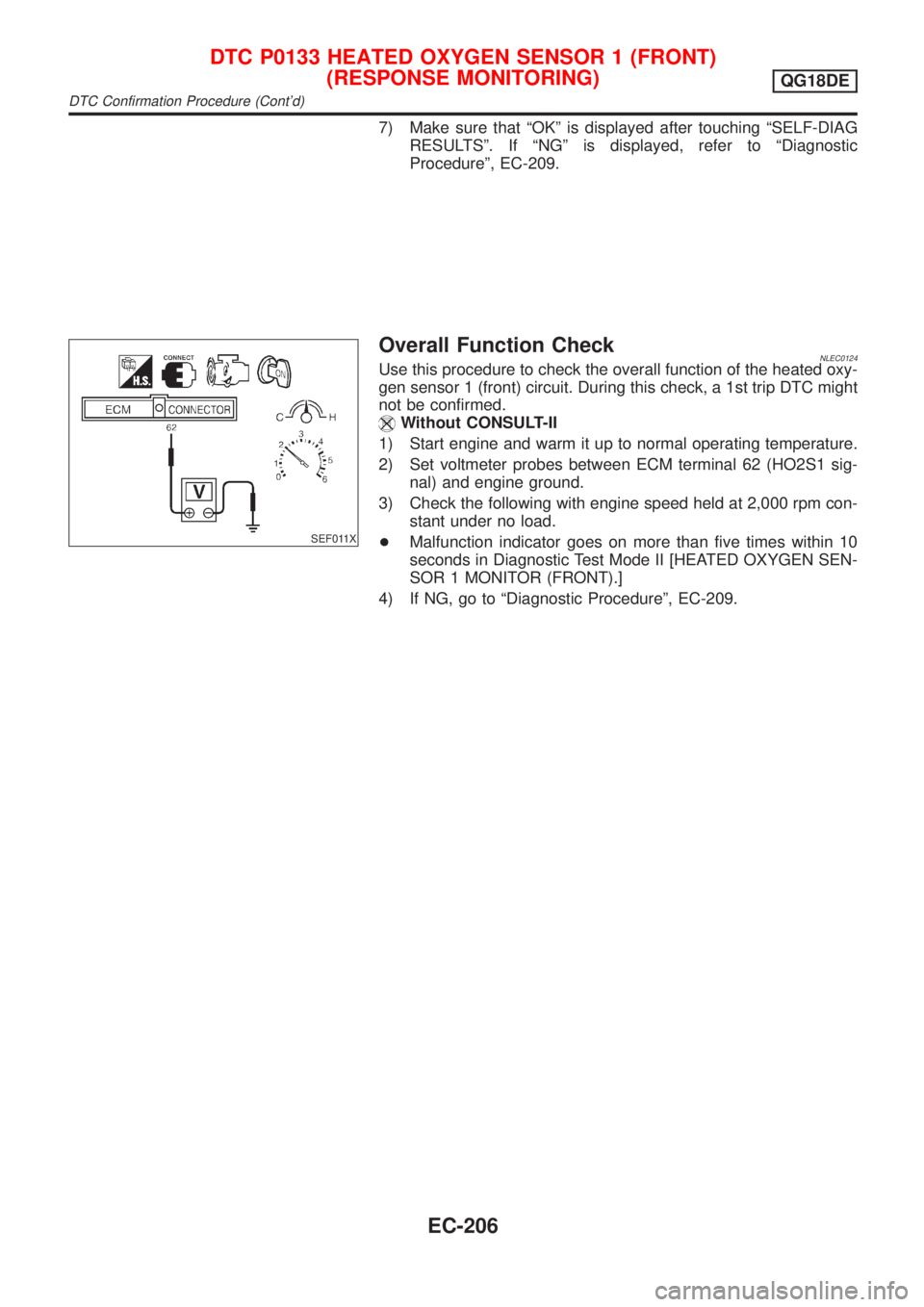
Overall Function CheckNLEC0124Use this procedure to check the overall function of the heated oxy-
gen sensor 1 (front) circuit. During this check, a 1st trip DTC might
not be confirmed.
Without CONSULT-II
1) Start engine and warm it up to normal operating temperature.
2) Set voltmeter probes between ECM terminal 62 (HO2S1 sig-
nal) and engine ground.
3) Check the following with engine speed held at 2,000 rpm con-
stant under no load.
+Malfunction indicator goes on more than five times within 10
seconds in Diagnostic Test Mode II [HEATED OXYGEN SEN-
SOR 1 MONITOR (FRONT).]
4) If NG, go to ªDiagnostic Procedureº, EC-209.
DTC P0133 HEATED OXYGEN SENSOR 1 (FRONT)
(RESPONSE MONITORING)
QG18DE
DTC Confirmation Procedure (Cont'd)
EC-206
Page 632 of 3051
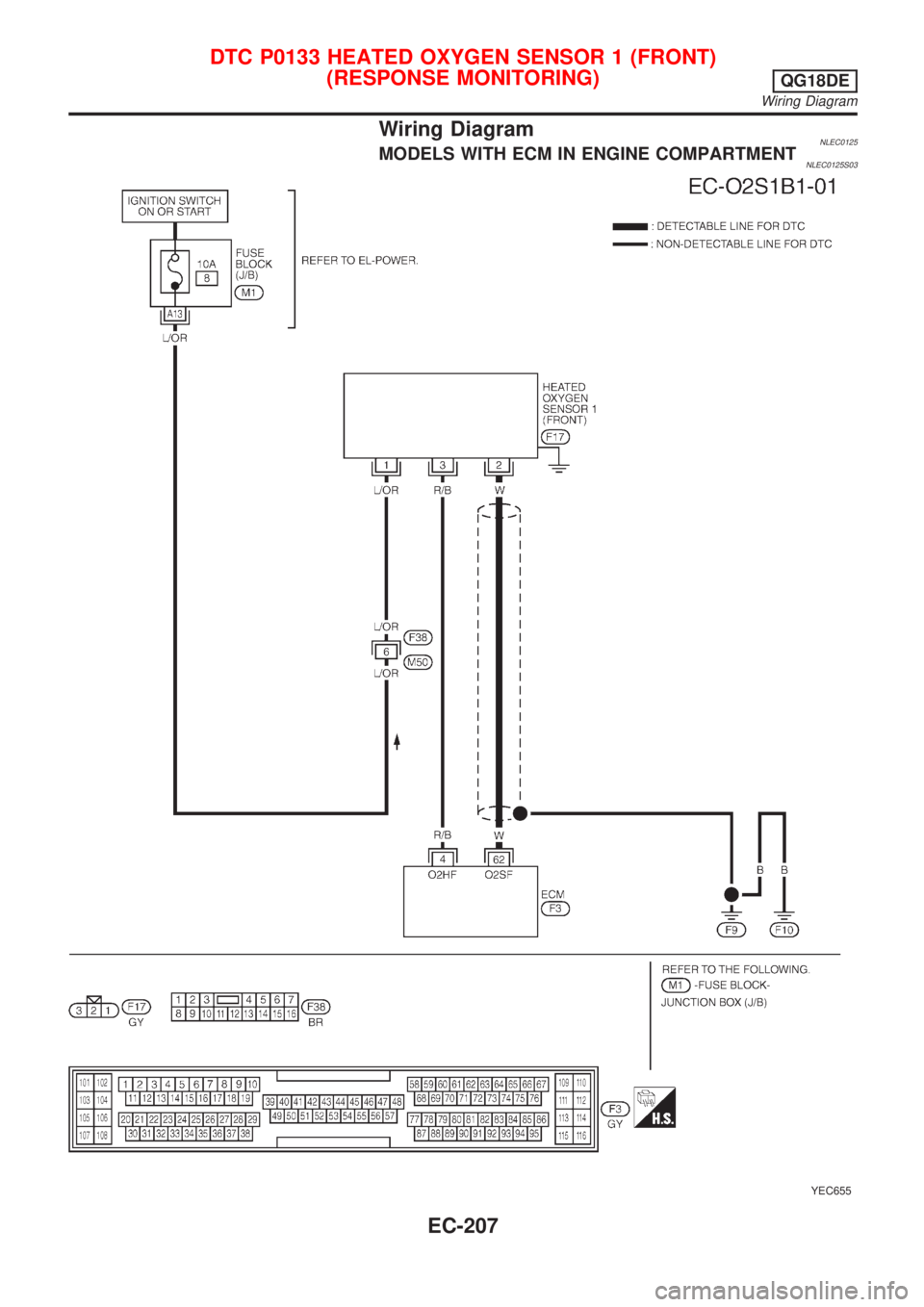
Wiring DiagramNLEC0125MODELS WITH ECM IN ENGINE COMPARTMENTNLEC0125S03
YEC655
DTC P0133 HEATED OXYGEN SENSOR 1 (FRONT)
(RESPONSE MONITORING)
QG18DE
Wiring Diagram
EC-207
Page 633 of 3051
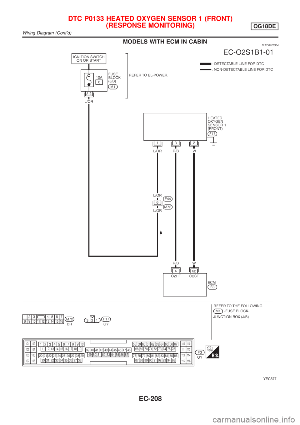
MODELS WITH ECM IN CABINNLEC0125S04
YEC877
DTC P0133 HEATED OXYGEN SENSOR 1 (FRONT)
(RESPONSE MONITORING)
QG18DE
Wiring Diagram (Cont'd)
EC-208
Page 634 of 3051
Diagnostic ProcedureNLEC0126
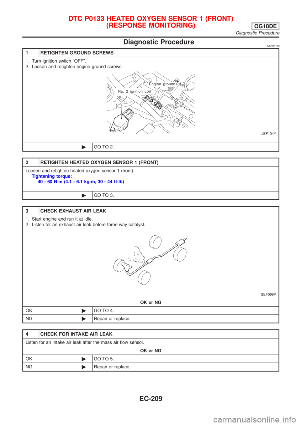
1 RETIGHTEN GROUND SCREWS
1. Turn ignition switch ªOFFº.
2. Loosen and retighten engine ground screws.
JEF104Y
©GO TO 2.
2 RETIGHTEN HEATED OXYGEN SENSOR 1 (FRONT)
Loosen and retighten heated oxygen sensor 1 (front).
Tightening torque:
40 - 60 N´m (4.1 - 6.1 kg-m, 30 - 44 ft-lb)
©GO TO 3.
3 CHECK EXHAUST AIR LEAK
1. Start engine and run it at idle.
2. Listen for an exhaust air leak before three way catalyst.
SEF099P
OK or NG
OK©GO TO 4.
NG©Repair or replace.
4 CHECK FOR INTAKE AIR LEAK
Listen for an intake air leak after the mass air flow sensor.
OK or NG
OK©GO TO 5.
NG©Repair or replace.
DTC P0133 HEATED OXYGEN SENSOR 1 (FRONT)
(RESPONSE MONITORING)
QG18DE
Diagnostic Procedure
EC-209