2001 NISSAN ALMERA TINO ESP
[x] Cancel search: ESPPage 301 of 3051

SEF233G
SEF234G
How to Perform Trouble Diagnoses for Quick
and Accurate Repair
NLBR0094INTRODUCTIONNLBR0094S01The ABS system has an electronic control unit to control major
functions. The control unit accepts input signals from sensors and
instantly drives actuator. It is essential that both kinds of signals are
proper and stable. It is also important to check for conventional
problems: such as air leaks in the booster or lines, lack of brake
fluid, or other problems with the brake system.
It is much more difficult to diagnose a problem that occurs intermit-
tently rather than continuously. Most intermittent problems are
caused by poor electric connections or faulty wiring. In this case,
careful checking of suspicious circuits may help prevent the
replacement of good parts.
A visual check only may not find the cause of the problems, so a
road test should be performed.
Before undertaking actual checks, take just a few minutes to talk
with a customer who approaches with a ABS complaint. The cus-
tomer is a very good source of information on such problems;
especially intermittent ones. Through the talks with the customer,
find out what symptoms are present and under what conditions
they occur.
Start your diagnosis by looking for“conventional”problems first.
This is one of the best ways to troubleshoot brake problems on an
ABS controlled vehicle. Also check related Service Bulletins for
information.
TROUBLE DIAGNOSIS—INTRODUCTIONABS
How to Perform Trouble Diagnoses for Quick and Accurate Repair
BR-64
Page 335 of 3051
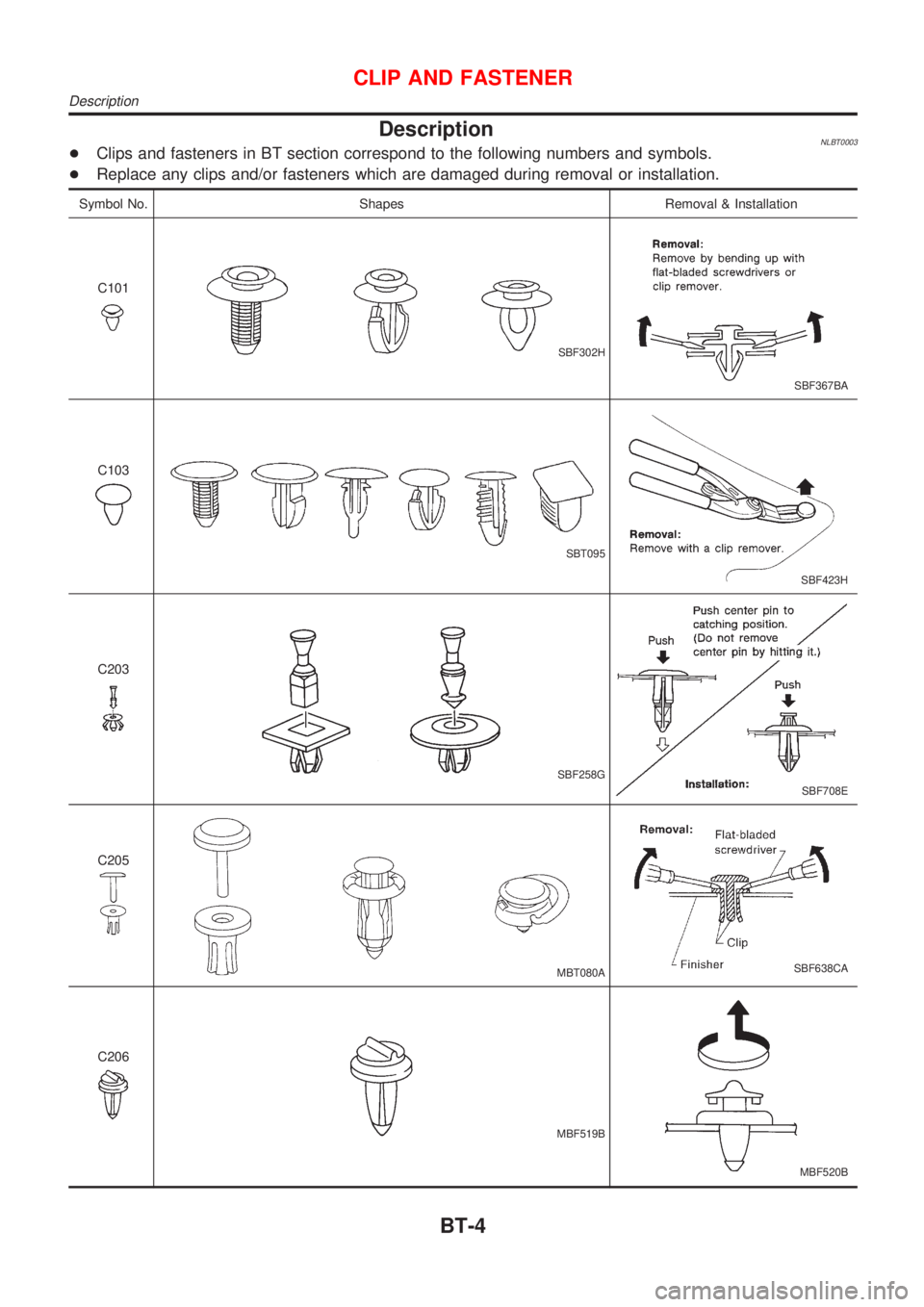
DescriptionNLBT0003+Clips and fasteners in BT section correspond to the following numbers and symbols.
+Replace any clips and/or fasteners which are damaged during removal or installation.
Symbol No. Shapes Removal & Installation
C101
SBF302H
SBF367BA
C103
SBT095
SBF423H
C203
SBF258G
SBF708E
C205
MBT080ASBF638CA
C206
MBF519B
MBF520B
CLIP AND FASTENER
Description
BT-4
Page 427 of 3051
DTC P0100 MASS AIR FLOW SENSOR (MAFS)......154
Component Description ...........................................154
CONSULT-II Reference Value in Data Monitor
Mode ........................................................................154
ECM Terminals and Reference Value .....................154
On Board Diagnosis Logic.......................................154
Fail-safe Mode .........................................................155
DTC Confirmation Procedure ..................................155
Wiring Diagram ........................................................156
Diagnostic Procedure ..............................................158
Component Inspection .............................................160
DTC P0110 INTAKE AIR TEMPERATURE
SENSOR......................................................................161
Component Description ...........................................161
On Board Diagnosis Logic.......................................162
DTC Confirmation Procedure ..................................162
Wiring Diagram ........................................................163
Diagnostic Procedure ..............................................165
Component Inspection .............................................167
DTC P0115 ENGINE COOLANT TEMPERATURE
SENSOR (ECTS) (CIRCUIT).......................................169
Component Description ...........................................169
CONSULT-II Reference Value in Data Monitor
Mode ........................................................................169
On Board Diagnosis Logic.......................................169
Fail-safe Mode .........................................................170
DTC Confirmation Procedure ..................................170
Wiring Diagram ........................................................171
Diagnostic Procedure ..............................................173
Component Inspection .............................................174
DTC P0120 THROTTLE POSITION SENSOR...........175
Component Description ...........................................175
CONSULT-II Reference Value in Data Monitor
Mode ........................................................................175
ECM Terminals and Reference Value .....................176
On Board Diagnosis Logic.......................................176
Fail-safe Mode .........................................................176
DTC Confirmation Procedure ..................................176
Wiring Diagram ........................................................178
Diagnostic Procedure ..............................................180
Component Inspection .............................................182
DTC P0130 HEATED OXYGEN SENSOR 1
(FRONT) (CIRCUIT).....................................................184
Component Description ...........................................184
CONSULT-II Reference Value in Data Monitor
Mode ........................................................................184
ECM Terminals and Reference Value .....................184
On Board Diagnosis Logic.......................................185
DTC Confirmation Procedure ..................................185
Overall Function Check ...........................................186
Wiring Diagram ........................................................187
Diagnostic Procedure ..............................................189Component Inspection .............................................190
DTC P0131 HEATED OXYGEN SENSOR 1
(FRONT) (LEAN SHIFT MONITORING).....................192
Component Description ...........................................192
CONSULT-II Reference Value in Data Monitor
Mode ........................................................................192
ECM Terminals and Reference Value .....................192
On Board Diagnosis Logic.......................................193
DTC Confirmation Procedure ..................................193
Overall Function Check ...........................................194
Diagnostic Procedure ..............................................194
Component Inspection .............................................196
DTC P0132 HEATED OXYGEN SENSOR 1
(FRONT) (RICH SHIFT MONITORING)......................198
Component Description ...........................................198
CONSULT-II Reference Value in Data Monitor
Mode ........................................................................198
ECM Terminals and Reference Value .....................198
On Board Diagnosis Logic.......................................199
DTC Confirmation Procedure ..................................199
Overall Function Check ...........................................200
Diagnostic Procedure ..............................................200
Component Inspection .............................................202
DTC P0133 HEATED OXYGEN SENSOR 1
(FRONT) (RESPONSE MONITORING).......................204
Component Description ...........................................204
CONSULT-II Reference Value in Data Monitor
Mode ........................................................................204
ECM Terminals and Reference Value .....................204
On Board Diagnosis Logic.......................................205
DTC Confirmation Procedure ..................................205
Overall Function Check ...........................................206
Wiring Diagram ........................................................207
Diagnostic Procedure ..............................................209
Component Inspection .............................................212
DTC P0134 HEATED OXYGEN SENSOR 1
(FRONT) (HIGH VOLTAGE)........................................214
Component Description ...........................................214
CONSULT-II Reference Value in Data Monitor
Mode ........................................................................214
ECM Terminals and Reference Value .....................214
On Board Diagnosis Logic.......................................215
DTC Confirmation Procedure ..................................215
Wiring Diagram ........................................................216
Diagnostic Procedure ..............................................218
Component Inspection .............................................219
DTC P0135 HEATED OXYGEN SENSOR 1
(FRONT) HEATER.......................................................221
Description ...............................................................221
CONSULT-II Reference Value in Data Monitor
Mode ........................................................................221
ECM Terminals and Reference Value .....................221
CONTENTS(Cont'd)
EC-2
Page 428 of 3051
On Board Diagnosis Logic.......................................221
DTC Confirmation Procedure ..................................222
Wiring Diagram ........................................................223
Diagnostic Procedure ..............................................225
Component Inspection .............................................226
DTC P0137 HEATED OXYGEN SENSOR 2
(REAR) (MIN. VOLTAGE MONITORING)...................227
Component Description ...........................................227
CONSULT-II Reference Value in Data Monitor
Mode ........................................................................227
ECM Terminals and Reference Value .....................227
On Board Diagnosis Logic.......................................227
DTC Confirmation Procedure ..................................228
Overall Function Check ...........................................229
Wiring Diagram ........................................................230
Diagnostic Procedure ..............................................232
Component Inspection .............................................235
DTC P0138 HEATED OXYGEN SENSOR 2
(REAR) (MAX. VOLTAGE MONITORING).................237
Component Description ...........................................237
CONSULT-II Reference Value in Data Monitor
Mode ........................................................................237
ECM Terminals and Reference Value .....................237
On Board Diagnosis Logic.......................................237
DTC Confirmation Procedure ..................................238
Overall Function Check ...........................................239
Wiring Diagram ........................................................240
Diagnostic Procedure ..............................................242
Component Inspection .............................................244
DTC P0139 HEATED OXYGEN SENSOR 2
(REAR) (RESPONSE MONITORING).........................246
Component Description ...........................................246
CONSULT-II Reference Value in Data Monitor
Mode ........................................................................246
ECM Terminals and Reference Value .....................246
On Board Diagnosis Logic.......................................246
DTC Confirmation Procedure ..................................247
Overall Function Check ...........................................248
Wiring Diagram ........................................................249
Diagnostic Procedure ..............................................251
Component Inspection .............................................254
DTC P0140 HEATED OXYGEN SENSOR 2
(REAR) (HIGH VOLTAGE)..........................................256
Component Description ...........................................256
CONSULT-II Reference Value in Data Monitor
Mode ........................................................................256
ECM Terminals and Reference Value .....................256
On Board Diagnosis Logic.......................................256
DTC Confirmation Procedure ..................................257
Overall Function Check ...........................................257
Wiring Diagram ........................................................258
Diagnostic Procedure ..............................................260Component Inspection .............................................261
DTC P0141 HEATED OXYGEN SENSOR 2
HEATER (REAR).........................................................263
Description ...............................................................263
CONSULT-II Reference Value in Data Monitor
Mode ........................................................................263
ECM Terminals and Reference Value .....................263
On Board Diagnosis Logic.......................................264
DTC Confirmation Procedure ..................................264
Wiring Diagram ........................................................265
Diagnostic Procedure ..............................................267
Component Inspection .............................................268
DTC P0171 FUEL INJECTION SYSTEM
FUNCTION (LEAN SIDE)............................................269
On Board Diagnosis Logic.......................................269
DTC Confirmation Procedure ..................................269
Wiring Diagram ........................................................271
Diagnostic Procedure ..............................................273
DTC P0172 FUEL INJECTION SYSTEM
FUNCTION (RICH SIDE).............................................277
On Board Diagnosis Logic.......................................277
DTC Confirmation Procedure ..................................277
Wiring Diagram ........................................................279
Diagnostic Procedure ..............................................281
DTC P0300 - P0304 NO.4-1CYLINDER
MISFIRE, MULTIPLE CYLINDER MISFIRE...............285
On Board Diagnosis Logic.......................................285
DTC Confirmation Procedure ..................................285
Diagnostic Procedure ..............................................286
DTC P0325 KNOCK SENSOR (KS)...........................291
Component Description ...........................................291
ECM Terminals and Reference Value .....................291
On Board Diagnosis Logic.......................................291
DTC Confirmation Procedure ..................................291
Wiring Diagram ........................................................292
Diagnostic Procedure ..............................................293
Component Inspection .............................................294
DTC P0335 CRANKSHAFT POSITION SENSOR
(POS)............................................................................295
Component Description ...........................................295
ECM Terminals and Reference Value .....................295
On Board Diagnosis Logic.......................................296
DTC Confirmation Procedure ..................................296
Wiring Diagram ........................................................297
Diagnostic Procedure ..............................................299
Component Inspection .............................................301
DTC P0340 CAMSHAFT POSITION SENSOR
(CMPS) (PHASE).........................................................302
Component Description ...........................................302
ECM Terminals and Reference Value .....................302
On Board Diagnosis Logic.......................................303
DTC Confirmation Procedure ..................................303
CONTENTS(Cont'd)
EC-3
Page 433 of 3051
DTC Confirmation Procedure ..................................695
Wiring Diagram ........................................................696
Diagnostic Procedure ..............................................698
Component Inspection .............................................699
DTC P0120 THROTTLE POSITION SENSOR...........700
Component Description ...........................................700
CONSULT-II Reference Value in Data Monitor
Mode ........................................................................700
ECM Terminals and Reference Value .....................701
On Board Diagnosis Logic.......................................701
Fail-safe Mode .........................................................701
DTC Confirmation Procedure ..................................701
Wiring Diagram ........................................................703
Diagnostic Procedure ..............................................705
Component Inspection .............................................707
DTC P0130 HEATED OXYGEN SENSOR 1
(FRONT) (CIRCUIT).....................................................709
Component Description ...........................................709
CONSULT-II Reference Value in Data Monitor
Mode ........................................................................709
ECM Terminals and Reference Value .....................709
On Board Diagnosis Logic.......................................710
DTC Confirmation Procedure ..................................710
Overall Function Check ........................................... 711
Wiring Diagram ........................................................712
Diagnostic Procedure ..............................................714
Component Inspection .............................................715
DTC P0131 HEATED OXYGEN SENSOR 1
(FRONT) (LEAN SHIFT MONITORING).....................717
Component Description ...........................................717
CONSULT-II Reference Value in Data Monitor
Mode ........................................................................717
ECM Terminals and Reference Value .....................717
On Board Diagnosis Logic.......................................718
DTC Confirmation Procedure ..................................718
Overall Function Check ...........................................719
Diagnostic Procedure ..............................................719
Component Inspection .............................................721
DTC P0132 HEATED OXYGEN SENSOR 1
(FRONT) (RICH SHIFT MONITORING)......................723
Component Description ...........................................723
CONSULT-II Reference Value in Data Monitor
Mode ........................................................................723
ECM Terminals and Reference Value .....................723
On Board Diagnosis Logic.......................................724
DTC Confirmation Procedure ..................................724
Overall Function Check ...........................................725
Diagnostic Procedure ..............................................725
Component Inspection .............................................727
DTC P0133 HEATED OXYGEN SENSOR 1
(FRONT) (RESPONSE MONITORING).......................729
Component Description ...........................................729CONSULT-II Reference Value in Data Monitor
Mode ........................................................................729
ECM Terminals and Reference Value .....................729
On Board Diagnosis Logic.......................................730
DTC Confirmation Procedure ..................................730
Overall Function Check ...........................................731
Wiring Diagram ........................................................732
Diagnostic Procedure ..............................................734
Component Inspection .............................................737
DTC P0134 HEATED OXYGEN SENSOR 1
(FRONT) (HIGH VOLTAGE)........................................739
Component Description ...........................................739
CONSULT-II Reference Value in Data Monitor
Mode ........................................................................739
ECM Terminals and Reference Value .....................739
On Board Diagnosis Logic.......................................740
DTC Confirmation Procedure ..................................740
Wiring Diagram ........................................................741
Diagnostic Procedure ..............................................743
Component Inspection .............................................744
DTC P0135 HEATED OXYGEN SENSOR 1
(FRONT) HEATER.......................................................746
Description ...............................................................746
CONSULT-II Reference Value in Data Monitor
Mode ........................................................................746
ECM Terminals and Reference Value .....................746
On Board Diagnosis Logic.......................................746
DTC Confirmation Procedure ..................................747
Wiring Diagram ........................................................748
Diagnostic Procedure ..............................................750
Component Inspection .............................................751
DTC P0137 HEATED OXYGEN SENSOR 2
(REAR) (MIN. VOLTAGE MONITORING)...................752
Component Description ...........................................752
CONSULT-II Reference Value in Data Monitor
Mode ........................................................................752
ECM Terminals and Reference Value .....................752
On Board Diagnosis Logic.......................................752
DTC Confirmation Procedure ..................................753
Overall Function Check ...........................................754
Wiring Diagram ........................................................755
Diagnostic Procedure ..............................................757
Component Inspection .............................................760
DTC P0138 HEATED OXYGEN SENSOR 2
(REAR) (MAX. VOLTAGE MONITORING).................761
Component Description ...........................................761
CONSULT-II Reference Value in Data Monitor
Mode ........................................................................761
ECM Terminals and Reference Value .....................761
On Board Diagnosis Logic.......................................761
DTC Confirmation Procedure ..................................762
Overall Function Check ...........................................763
CONTENTS(Cont'd)
EC-8
Page 434 of 3051
Wiring Diagram ........................................................764
Diagnostic Procedure ..............................................766
Component Inspection .............................................769
DTC P0139 HEATED OXYGEN SENSOR 2
(REAR) (RESPONSE MONITORING).........................770
Component Description ...........................................770
CONSULT-II Reference Value in Data Monitor
Mode ........................................................................770
ECM Terminals and Reference Value .....................770
On Board Diagnosis Logic.......................................770
DTC Confirmation Procedure ..................................771
Overall Function Check ...........................................772
Wiring Diagram ........................................................773
Diagnostic Procedure ..............................................775
Component Inspection .............................................778
DTC P0140 HEATED OXYGEN SENSOR 2
(REAR) (HIGH VOLTAGE)..........................................779
Component Description ...........................................779
CONSULT-II Reference Value in Data Monitor
Mode ........................................................................779
ECM Terminals and Reference Value .....................779
On Board Diagnosis Logic.......................................779
DTC Confirmation Procedure ..................................780
Overall Function Check ...........................................780
Wiring Diagram ........................................................781
Diagnostic Procedure ..............................................783
Component Inspection .............................................784
DTC P0141 HEATED OXYGEN SENSOR 2
HEATER (REAR).........................................................786
Description ...............................................................786
CONSULT-II Reference Value in Data Monitor
Mode ........................................................................786
ECM Terminals and Reference Value .....................786
On Board Diagnosis Logic.......................................786
DTC Confirmation Procedure ..................................787
Wiring Diagram ........................................................788
Diagnostic Procedure ..............................................790
Component Inspection .............................................791
DTC P0171 FUEL INJECTION SYSTEM
FUNCTION (LEAN SIDE)............................................792
On Board Diagnosis Logic.......................................792
DTC Confirmation Procedure ..................................792
Wiring Diagram ........................................................794
Diagnostic Procedure ..............................................796
DTC P0172 FUEL INJECTION SYSTEM
FUNCTION (RICH SIDE).............................................800
On Board Diagnosis Logic.......................................800
DTC Confirmation Procedure ..................................800
Wiring Diagram ........................................................802
Diagnostic Procedure ..............................................804DTC P0300 - P0304 NO.4-1CYLINDER
MISFIRE, MULTIPLE CYLINDER MISFIRE...............808
On Board Diagnosis Logic.......................................808
DTC Confirmation Procedure ..................................808
Diagnostic Procedure ..............................................809
Component Inspection .............................................814
DTC P0325 KNOCK SENSOR (KS)...........................815
Component Description ...........................................815
ECM Terminals and Reference Value .....................815
On Board Diagnosis Logic.......................................815
DTC Confirmation Procedure ..................................815
Wiring Diagram ........................................................816
Diagnostic Procedure ..............................................817
Component Inspection .............................................818
DTC P0335 CRANKSHAFT POSITION SENSOR
(CKPS) (OBD)..............................................................819
Component Description ...........................................819
ECM Terminals and Reference Value .....................819
On Board Diagnosis Logic.......................................819
DTC Confirmation Procedure ..................................820
Wiring Diagram ........................................................821
Diagnostic Procedure ..............................................823
Component Inspection .............................................824
DTC P0340 CAMSHAFT POSITION SENSOR
(CMPS).........................................................................825
Component Description ...........................................825
ECM Terminals and Reference Value .....................825
On Board Diagnosis Logic.......................................826
DTC Confirmation Procedure ..................................826
Wiring Diagram ........................................................828
Diagnostic Procedure ..............................................830
Component Inspection .............................................833
DTC P0400 EGR FUNCTION (CLOSED) (WHERE
FITTED)........................................................................834
Description ...............................................................834
CONSULT-II Reference Value in Data Monitor
Mode ........................................................................835
ECM Terminals and Reference Value .....................835
On Board Diagnosis Logic.......................................835
DTC Confirmation Procedure ..................................836
Wiring Diagram ........................................................838
Diagnostic Procedure ..............................................839
DTC P0403 EGR VOLUME CONTROL VALVE
(CIRCUIT) (WHERE FITTED)......................................841
Description ...............................................................841
CONSULT-II Reference Value in Data Monitor
Mode ........................................................................842
ECM Terminals and Reference Value .....................842
On Board Diagnosis Logic.......................................842
DTC Confirmation Procedure ..................................842
Wiring Diagram ........................................................844
Diagnostic Procedure ..............................................845
CONTENTS(Cont'd)
EC-9
Page 446 of 3051
Precautions for Supplemental Restraint System
(SRS) ªAIR BAGº and ªSEAT BELT
PRE-TENSIONERº
NLEC1262The Supplemental Restraint System ªAIR BAGº and ªSEAT BELT PRE-TENSIONERº, used along with a seat
belt, help to reduce the risk or severity of injury to the driver and front passenger in a frontal collision. The
Supplemental Restraint System consists of air bag modules (located in the center of the steering wheel and
on the instrument panel on the passenger side), seat belt pre-tensioners, a diagnosis sensor unit, warning
lamp, wiring harness and spiral cable.
In addition to the supplemental air bag modules for a frontal collision, the supplemental side air bag used along
with the seat belt helps to reduce the risk or severity of injury to the driver and front passenger in a side col-
lision. The supplemental side air bag consists of air bag modules (located in the outer side of front seats),
satellite sensor, diagnosis sensor unit (one of components of supplemental air bags for a frontal collision),
wiring harness, warning lamp (one of components of supplemental air bags for a frontal collision). Information
necessary to service the system safely is included in theRS sectionof this Service Manual.
WARNING:
+To avoid rendering the SRS inoperative, which could increase the risk of personal injury or death
in the event of a collision which would result in air bag inflation, all maintenance must be performed
by an authorized NISSAN dealer.
+Improper maintenance, including incorrect removal and installation of the SRS, can lead to per-
sonal injury caused by unintentional activation of the system.
+Do not use electrical test equipment on any circuit related to the SRS unless instructed to in this
Service Manual. SRS wiring harnesses can be identified with yellow harness connector (and with
yellow harness protector or yellow insulation tape before the harness connectors).
Precautions for On Board Diagnostic (OBD)
System of Engine
NLEC0003The ECM has an on board diagnostic system. It will light up the malfunction indicator (MI) to warn the driver
of a malfunction causing emission deterioration.
CAUTION:
+Be sure to turn the ignition switch ªOFFº and disconnect the negative battery terminal before any
repair or inspection work. The open/short circuit of related switches, sensors, solenoid valves, etc.
will cause the MI to light up.
+Be sure to connect and lock the connectors securely after work. A loose (unlocked) connector will
cause the MI to light up due to the open circuit. (Be sure the connector is free from water, grease,
dirt, bent terminals, etc.)
+Certain systems and components, especially those related to OBD, may use a new style slide-
locking type harness connector.
For description and how to disconnect, refer to EL section, ªDescriptionº, ªHARNESS CONNEC-
TORº.
+Be sure to route and secure the harnesses properly after work. The interference of the harness with
a bracket, etc. may cause the MI to light up due to the short circuit.
+Be sure to connect rubber tubes properly after work. A misconnected or disconnected rubber tube
may cause the MI to light up due to the malfunction of fuel injection system, etc.
+Be sure to erase the unnecessary malfunction information (repairs completed) from the ECM before
returning the vehicle to the customer.
PRECAUTIONSQG18DE
Precautions for Supplemental Restraint System (SRS) ªAIR BAGº and ªSEAT BELT PRE-TENSIONERº
EC-21
Page 474 of 3051
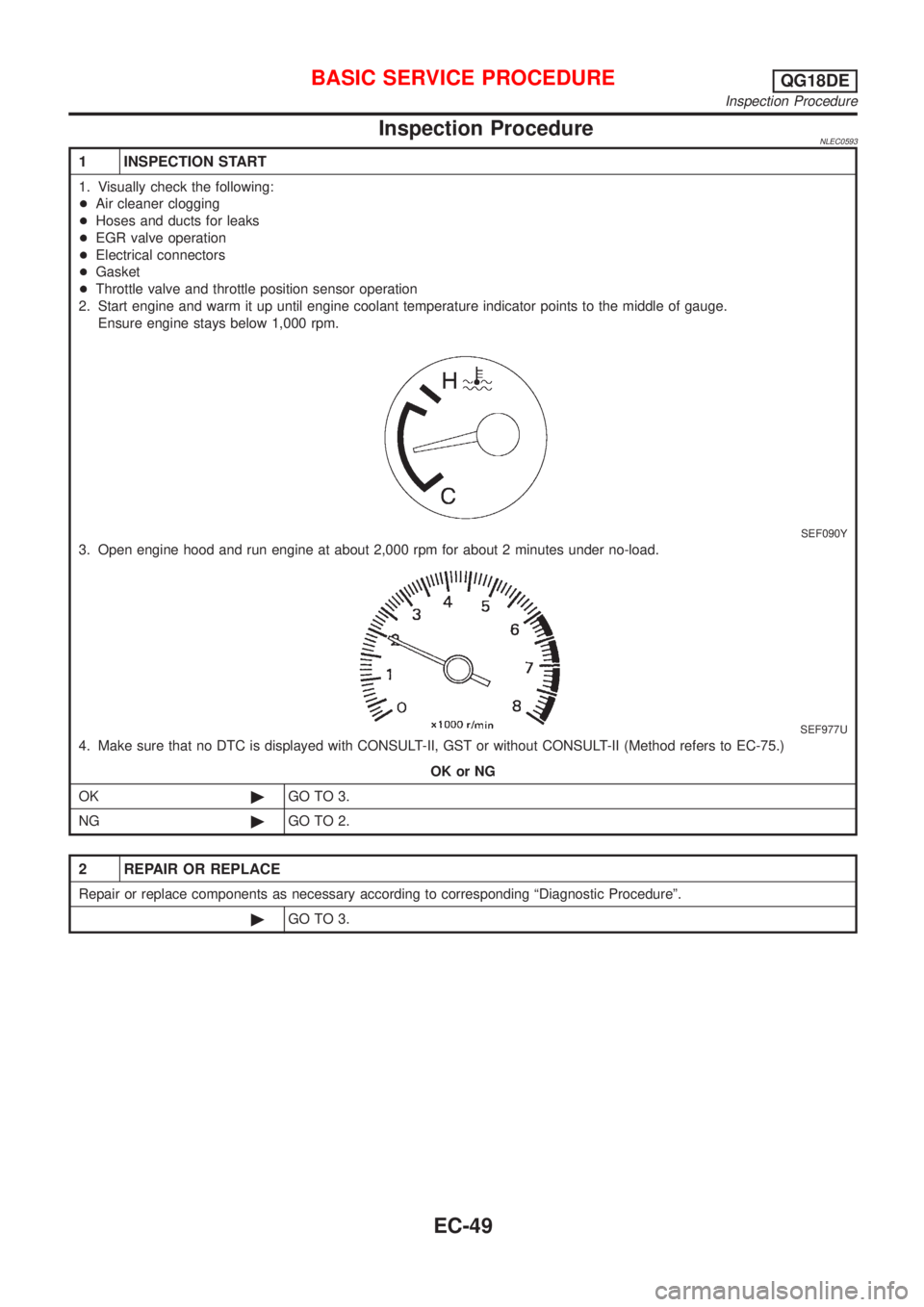
Inspection ProcedureNLEC0593
1 INSPECTION START
1. Visually check the following:
+Air cleaner clogging
+Hoses and ducts for leaks
+EGR valve operation
+Electrical connectors
+Gasket
+Throttle valve and throttle position sensor operation
2. Start engine and warm it up until engine coolant temperature indicator points to the middle of gauge.
Ensure engine stays below 1,000 rpm.
SEF090Y
3. Open engine hood and run engine at about 2,000 rpm for about 2 minutes under no-load.
SEF977U
4. Make sure that no DTC is displayed with CONSULT-II, GST or without CONSULT-II (Method refers to EC-75.)
OK or NG
OK©GO TO 3.
NG©GO TO 2.
2 REPAIR OR REPLACE
Repair or replace components as necessary according to corresponding ªDiagnostic Procedureº.
©GO TO 3.
BASIC SERVICE PROCEDUREQG18DE
Inspection Procedure
EC-49