2001 NISSAN ALMERA TINO service indicator
[x] Cancel search: service indicatorPage 2508 of 3051

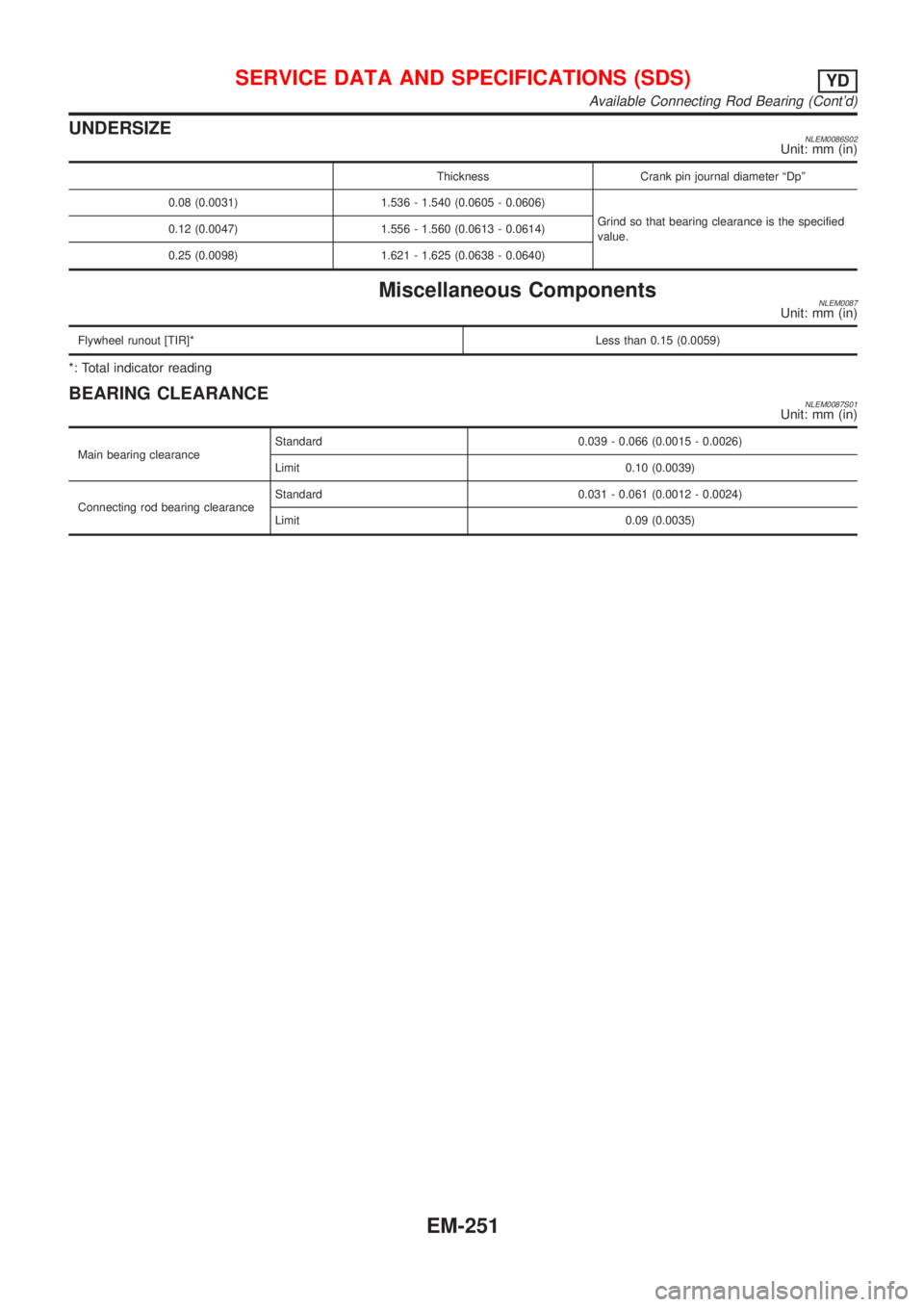
UNDERSIZENLEM0086S02Unit: mm (in)
Thickness Crank pin journal diameter ªDpº
0.08 (0.0031) 1.536 - 1.540 (0.0605 - 0.0606)
Grind so that bearing clearance is the specified
value. 0.12 (0.0047) 1.556 - 1.560 (0.0613 - 0.0614)
0.25 (0.0098) 1.621 - 1.625 (0.0638 - 0.0640)
Miscellaneous ComponentsNLEM0087Unit: mm (in)
Flywheel runout [TIR]*Less than 0.15 (0.0059)
*: Total indicator reading
BEARING CLEARANCENLEM0087S01Unit: mm (in)
Main bearing clearanceStandard 0.039 - 0.066 (0.0015 - 0.0026)
Limit 0.10 (0.0039)
Connecting rod bearing clearanceStandard 0.031 - 0.061 (0.0012 - 0.0024)
Limit 0.09 (0.0035)
SERVICE DATA AND SPECIFICATIONS (SDS)YD
Available Connecting Rod Bearing (Cont'd)
EM-251
Page 2543 of 3051

The security indicator is located on the instrument panel. The indi-
cator blinks when the ignition switch is in“OFF”or“ACC”position.
Therefore, NATS warns outsiders that the vehicle is equipped with
the anti-theft system.
+When NATS detects trouble, the security indicator lamp lights
up while ignition switch is in“ON”position.
This lighting up indicates that the anti-theft is not functioning,
so prompt service is required.
+When servicing NATS (trouble diagnoses, system initialization
and additional registration of other NATS ignition key IDs),
CONSULT-II hardware and CONSULT-II NATS software is
necessary.
Regarding the procedures of NATS initialization and NATS
ignition key ID registration, refer to CONSULT-II operation
manual, NATS.
Therefore, CONSULT-II NATS software (program card and
operation manual) must be kept strictly confidential to main-
tain the integrity of the anti-theft function.
+When servicing NATS (trouble diagnoses, system initialization
and additional registration of other NATS ignition key IDs), it
may be necessary to re-register original key identification.
Therefore, be sure to receive all keys from vehicle owner. A
maximum of five key IDs can be registered into NATS.
+When failing to start the engine first time using the key of
NATS, start as follows.
a) Leave the ignition key in“ON”position for approximately 5
seconds.
b) Turn ignition key to“OFF”or“LOCK”position and wait approxi-
mately 5 seconds.
c) Repeat step 1 and 2 again.
d) Restart the engine while keeping the key separate from any
others on key-chain.
SGI285
GENERAL PRECAUTIONSNLGI0001S03+Do not operate the engine for an extended period of time
without proper exhaust ventilation.
Keep the work area well ventilated and free of any inflammable
materials. Special care should be taken when handling any
inflammable or poisonous materials, such as gasoline, refrig-
erant gas, etc. When working in a pit or other enclosed area,
be sure to properly ventilate the area before working with haz-
ardous materials.
Do not smoke while working on the vehicle.
SGI231
+Before jacking up the vehicle, apply wheel chocks or other tire
blocks to the wheels to prevent the vehicle from moving. After
jacking up the vehicle, support the vehicle weight with safety
stands at the points designated for proper lifting before work-
ing on the vehicle.
These operations should be done on a level surface.
+When removing a heavy component such as the engine or
transaxle, be careful not to lose your balance and drop them.
Also, do not allow them to strike adjacent parts, especially the
brake tubes and master cylinder.
PRECAUTIONS
Precautions (Cont’d)
GI-4
Page 2589 of 3051

NEW TERMNEW ACRONYM /
ABBREVIATIONOLD TERM
Manifold absolute pressure MAP ***
Manifold absolute pressure/Barometric
pressure switch solenoid valveMAP/BARO switch solenoid valve ***
Manifold absolute pressure sensor MAPS ***
Manifold differential pressure MDP ***
Manifold differential pressure sensor MDPS ***
Manifold surface temperature MST ***
Manifold surface temperature sensor MSTS ***
Manifold vacuum zone MVZ ***
Manifold vacuum zone sensor MVZS ***
Mass air flow sensor MAFS Air flow meter
Mixture control solenoid valve MC solenoid valve Air-fuel ratio control solenoid valve
Multiport fuel injection system MFI system Fuel injection control
Neutral position switch *** Neutral switch
Nonvolatile random access memory NVRAM ***
On board diagnostic system OBD system Self-diagnoses
Open loop OL Open loop
Oxidation catalyst OC Catalyst
Oxidation catalytic converter system OC system ***
Oxygen sensor O2S Exhaust gas sensor
Park position switch *** Park switch
Park/neutral position switch PNP switch Park/neutral switch
Periodic trap oxidizer system PTOX system ***
Powertrain control module PCM ***
Programmable read only memory PROM ***
Pulsed secondary air injection control
solenoid valvePAIRC solenoid valve AIV control solenoid valve
Pulsed secondary air injection system PAIR system Air induction valve (AIV) control
Pulsed secondary air injection valve PAIR valve Air induction valve
Random access memory RAM ***
Read only memory ROM ***
Scan tool ST ***
Secondary air injection pump AIR pump ***
Secondary air injection system AIR system ***
Sequential multiport fuel injection system SFI system Sequential fuel injection
Service reminder indicator SRI ***
Simultaneous multiport fuel injection sys-
tem*** Simultaneous fuel injection
ISO 15031–2 TERMINOLOGY LIST
ISO 15031–2 Terminology List (Cont’d)
GI-50
Page 2889 of 3051

INPUT SHAFT BEARING ADJUSTING SHIMNLMT0029S05
Thickness mm (in) Part number*
0.40 (0.0157)
0.44 (0.0173)
0.48 (0.0189)
0.52 (0.0205)
0.56 (0.0220)
0.60 (0.0236)
0.64 (0.0252)
0.68 (0.0268)
0.72 (0.0283)
0.76 (0.0299)
0.80 (0.0315)
1.20 (0.0472)32225-08E00
32225-08E01
32225-08E02
32225-08E03
32225-08E04
32225-08E05
32225-08E06
32225-08E07
32225-08E08
32225-08E09
32225-08E10
32225-08E11
*: Always check with the Parts Department for the latest parts information.
TABLE FOR SELECTING INPUT SHAFT BEARING ADJUSTING SHIM(S)NLMT0029S06Unit: mm (in)
Dial indicator indication Suitable shim(s)
0.65 - 0.69 (0.0256 - 0.0272)
0.69 - 0.73 (0.0272 - 0.0287)
0.73 - 0.77 (0.0287 - 0.0303)
0.77 - 0.81 (0.0303 - 0.0319)
0.81 - 0.85 (0.0319 - 0.0335)
0.85 - 0.89 (0.0335 - 0.0350)
0.89 - 0.93 (0.0350 - 0.0366)
0.93 - 0.97 (0.0366 - 0.0382)
0.97 - 1.01 (0.0382 - 0.0398)
1.01 - 1.05 (0.0398 - 0.0413)
1.05 - 1.09 (0.0413 - 0.0429)
1.09 - 1.13 (0.0429 - 0.0445)
1.13 - 1.17 (0.0445 - 0.0461)
1.17 - 1.21 (0.0461 - 0.0476)
1.21 - 1.25 (0.0476 - 0.0492)
1.25 - 1.29 (0.0492 - 0.0508)
1.29 - 1.33 (0.0508 - 0.0524)
1.33 - 1.37 (0.0524 - 0.0539)
1.37 - 1.41 (0.0539 - 0.0555)
1.41 - 1.45 (0.0555 - 0.0571)
1.45 - 1.49 (0.0571 - 0.0587)
1.49 - 1.53 (0.0587 - 0.0602)
1.53 - 1.57 (0.0602 - 0.0618)
1.57 - 1.61 (0.0618 - 0.0634)
1.61 - 1.65 (0.0634 - 0.0650)
1.65 - 1.69 (0.0650 - 0.0665)0.64 (0.0252)
0.68 (0.0268)
0.72 (0.0283)
0.76 (0.0299)
0.80 (0.0315)
0.40 + 0.44 (0.0157 + 0.0173)
0.44 + 0.44 (0.0173 + 0.0173)
0.44 + 0.48 (0.0173 + 0.0189)
0.48 + 0.48 (0.0189 + 0.0189)
0.48 + 0.52 (0.0189 + 0.0205)
0.52 + 0.52 (0.0205 + 0.0205)
0.52 + 0.56 (0.0205 + 0.0220)
0.56 + 0.56 (0.0220 + 0.0220)
0.56 + 0.60 (0.0220 + 0.0236)
0.60 + 0.60 (0.0236 + 0.0236)
0.60 + 0.64 (0.0236 + 0.0252)
0.64 + 0.64 (0.0252 + 0.0252)
0.64 + 0.68 (0.0252 + 0.0268)
0.68 + 0.68 (0.0268 + 0.0268)
0.68 + 0.72 (0.0268 + 0.0283)
0.72 + 0.72 (0.0283 + 0.0283)
0.72 + 0.76 (0.0283 + 0.0299)
0.76 + 0.76 (0.0299 + 0.0299)
0.76 + 0.80 (0.0299 + 0.0315)
0.80 + 0.80 (0.0315 + 0.0315)
0.44 + 1.20 (0.0173 + 0.0472)
DIFFERENTIAL SIDE BEARING ADJUSTING SHIMNLMT0029S07
Thickness mm (in) Part number*
0.40 (0.0157)
0.44 (0.0173)
0.48 (0.0189)
0.52 (0.0205)
0.56 (0.0220)
0.60 (0.0236)
0.64 (0.0252)
0.68 (0.0268)
0.72 (0.0283)
0.76 (0.0299)
0.80 (0.0315)
0.84 (0.0331)
0.88 (0.0346)
1.20 (0.0472)38453-96E00
38453-96E01
38453-96E02
38453-96E03
38453-96E04
38453-96E05
38453-96E06
38453-96E07
38453-96E08
38453-96E09
38453-96E10
38453-96E11
38453-96E12
38453-96E13
*: Always check with the Parts Department for the latest parts information.
SERVICE DATA AND SPECIFICATIONS (SDS)RS5F50A
Available Shims (Cont’d)
MT-100
Page 2890 of 3051

TABLE FOR SELECTING DIFFERENTIAL SIDE BEARING ADJUSTING SHIM(S)=NLMT0029S08Unit: mm (in)
Dial indicator deflection Suitable shim(s)
0.47 - 0.51 (0.0185 - 0.0201)
0.51 - 0.55 (0.0201 - 0.0217)
0.55 - 0.59 (0.0217 - 0.0232)
0.59 - 0.63 (0.0232 - 0.0248)
0.63 - 0.67 (0.0248 - 0.0264)
0.67 - 0.71 (0.0264 - 0.0280)
0.71 - 0.75 (0.0280 - 0.0295)
0.75 - 0.79 (0.0295 - 0.0311)
0.79 - 0.83 (0.0311 - 0.0327)
0.83 - 0.87 (0.0327 - 0.0343)
0.87 - 0.91 (0.0343 - 0.0358)
0.91 - 0.95 (0.0358 - 0.0374)
0.95 - 0.99 (0.0374 - 0.0390)
0.99 - 1.03 (0.0390 - 0.0406)
1.03 - 1.07 (0.0406 - 0.0421)
1.07 - 1.11 (0.0421 - 0.0437)
1.11 - 1.15 (0.0437 - 0.0453)
1.15 - 1.19 (0.0453 - 0.0469)
1.19 - 1.23 (0.0469 - 0.0484)
1.23 - 1.27 (0.0484 - 0.0500)
1.27 - 1.31 (0.0500 - 0.0516)0.44 + 0.48 (0.0173 + 0.0189)
0.48 + 0.48 (0.0189 + 0.0189)
0.48 + 0.52 (0.0189 + 0.0205)
0.52 + 0.52 (0.0205 + 0.0205)
0.52 + 0.56 (0.0205 + 0.0220)
0.56 + 0.56 (0.0220 + 0.0220)
0.56 + 0.60 (0.0220 + 0.0236)
0.60 + 0.60 (0.0236 + 0.0236)
0.60 + 0.64 (0.0236 + 0.0252)
0.64 + 0.64 (0.0252 + 0.0252)
0.64 + 0.68 (0.0252 + 0.0268)
0.68 + 0.68 (0.0268 + 0.0268)
0.68 + 0.72 (0.0268 + 0.0283)
0.72 + 0.72 (0.0283 + 0.0283)
0.72 + 0.76 (0.0283 + 0.0299)
0.76 + 0.76 (0.0299 + 0.0299)
0.76 + 0.80 (0.0299 + 0.0315)
0.80 + 0.80 (0.0315 + 0.0315)
0.44 + 1.20 (0.0173 + 0.0472)
0.48 + 1.20 (0.0189 + 0.0472)
0.52 + 1.20 (0.0205 + 0.0472)
SERVICE DATA AND SPECIFICATIONS (SDS)RS5F50A
Available Shims (Cont’d)
MT-101
Page 2962 of 3051

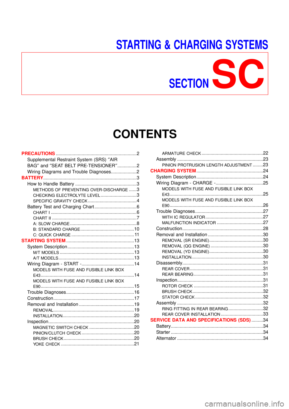
STARTING & CHARGING SYSTEMS
SECTION
SC
CONTENTS
PRECAUTIONS...............................................................2
Supplemental Restraint System (SRS)″AIR
BAG″and″SEAT BELT PRE-TENSIONER″...............2
Wiring Diagrams and Trouble Diagnoses....................2
BATTERY.........................................................................3
How to Handle Battery ................................................3
METHODS OF PREVENTING OVER-DISCHARGE......3
CHECKING ELECTROLYTE LEVEL............................3
SPECIFIC GRAVITY CHECK......................................4
Battery Test and Charging Chart .................................6
CHART I...................................................................6
CHART II..................................................................7
A: SLOW CHARGE....................................................8
B: STANDARD CHARGE..........................................10
C: QUICK CHARGE................................................. 11
STARTING SYSTEM.....................................................13
System Description ....................................................13
M/T MODELS..........................................................13
A/T MODELS...........................................................13
Wiring Diagram - START -.........................................14
MODELS WITH FUSE AND FUSIBLE LINK BOX
E43
.........................................................................14
MODELS WITH FUSE AND FUSIBLE LINK BOX
E90
.........................................................................15
Trouble Diagnoses.....................................................16
Construction ...............................................................17
Removal and Installation ...........................................19
REMOVAL...............................................................19
INSTALLATION........................................................20
Inspection...................................................................20
MAGNETIC SWITCH CHECK...................................20
PINION/CLUTCH CHECK.........................................20
BRUSH CHECK.......................................................20
YOKE CHECK.........................................................21
ARMATURE CHECK................................................22
Assembly ...................................................................23
PINION PROTRUSION LENGTH ADJUSTMENT........23
CHARGING SYSTEM....................................................24
System Description ....................................................24
Wiring Diagram - CHARGE -.....................................25
MODELS WITH FUSE AND FUSIBLE LINK BOX
E43
.........................................................................25
MODELS WITH FUSE AND FUSIBLE LINK BOX
E90
.........................................................................26
Trouble Diagnoses.....................................................27
WITH IC REGULATOR.............................................27
MALFUNCTION INDICATOR....................................27
Construction ...............................................................28
Removal and Installation ...........................................30
REMOVAL (SR ENGINE)..........................................30
REMOVAL (QG ENGINE).........................................30
REMOVAL (YD ENGINE)..........................................30
INSTALLATION........................................................30
Disassembly...............................................................31
REAR COVER.........................................................31
REAR BEARING......................................................31
Inspection...................................................................31
ROTOR CHECK......................................................31
BRUSH CHECK.......................................................32
STATOR CHECK.....................................................32
Assembly ...................................................................32
RING FITTING IN REAR BEARING...........................32
REAR COVER INSTALLATION.................................33
SERVICE DATA AND SPECIFICATIONS (SDS).........34
Battery........................................................................34
Starter ........................................................................34
Alternator ...................................................................34
Page 3029 of 3051

SMA525A
On-vehicle Service
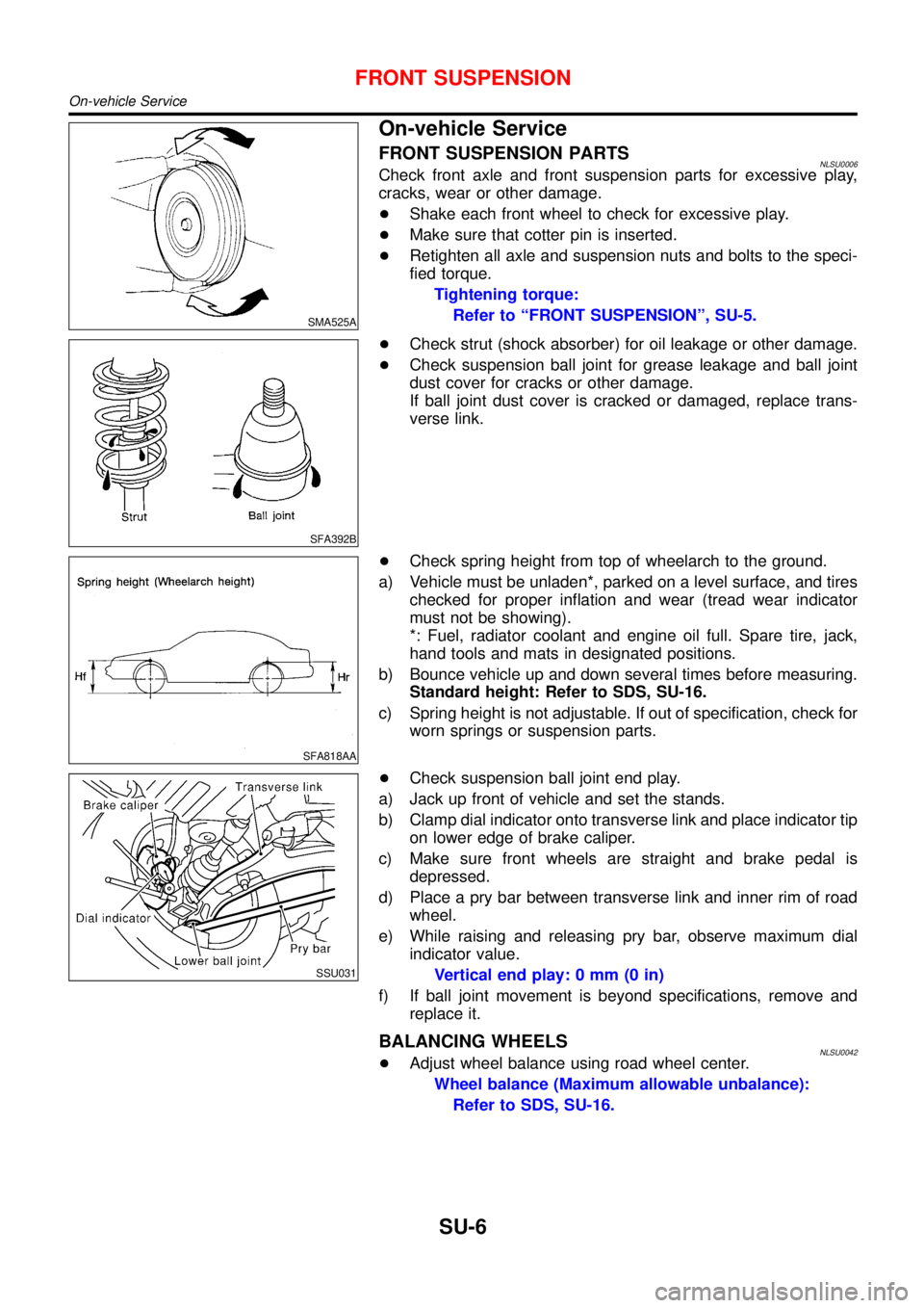
FRONT SUSPENSION PARTSNLSU0006Check front axle and front suspension parts for excessive play,
cracks, wear or other damage.
+Shake each front wheel to check for excessive play.
+Make sure that cotter pin is inserted.
+Retighten all axle and suspension nuts and bolts to the speci-
fied torque.
Tightening torque:
Refer to “FRONT SUSPENSION”, SU-5.
SFA392B
+Check strut (shock absorber) for oil leakage or other damage.
+Check suspension ball joint for grease leakage and ball joint
dust cover for cracks or other damage.
If ball joint dust cover is cracked or damaged, replace trans-
verse link.
SFA818AA
+Check spring height from top of wheelarch to the ground.
a) Vehicle must be unladen*, parked on a level surface, and tires
checked for proper inflation and wear (tread wear indicator
must not be showing).
*: Fuel, radiator coolant and engine oil full. Spare tire, jack,
hand tools and mats in designated positions.
b) Bounce vehicle up and down several times before measuring.
Standard height: Refer to SDS, SU-16.
c) Spring height is not adjustable. If out of specification, check for
worn springs or suspension parts.
SSU031
+Check suspension ball joint end play.
a) Jack up front of vehicle and set the stands.
b) Clamp dial indicator onto transverse link and place indicator tip
on lower edge of brake caliper.
c) Make sure front wheels are straight and brake pedal is
depressed.
d) Place a pry bar between transverse link and inner rim of road
wheel.
e) While raising and releasing pry bar, observe maximum dial
indicator value.
Vertical end play: 0 mm (0 in)
f) If ball joint movement is beyond specifications, remove and
replace it.
BALANCING WHEELSNLSU0042+Adjust wheel balance using road wheel center.
Wheel balance (Maximum allowable unbalance):
Refer to SDS, SU-16.
FRONT SUSPENSION
On-vehicle Service
SU-6
Page 3030 of 3051

SFA975B
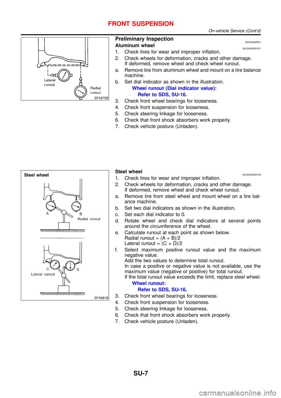
Preliminary InspectionNLSU0042S01Aluminum wheelNLSU0042S01011. Check tires for wear and improper inflation.
2. Check wheels for deformation, cracks and other damage.
If deformed, remove wheel and check wheel runout.
a. Remove tire from aluminum wheel and mount on a tire balance
machine.
b. Set dial indicator as shown in the illustration.
Wheel runout (Dial indicator value):
Refer to SDS, SU-16.
3. Check front wheel bearings for looseness.
4. Check front suspension for looseness.
5. Check steering linkage for looseness.
6. Check that front shock absorbers work properly.
7. Check vehicle posture (Unladen).
SFA981B
Steel wheelNLSU0042S01021. Check tires for wear and improper inflation.
2. Check wheels for deformation, cracks and other damage.
If deformed, remove wheel and check wheel runout.
a. Remove tire from steel wheel and mount wheel on a tire bal-
ance machine.
b. Set two dial indicators as shown in the illustration.
c. Set each dial indicator to 0.
d. Rotate wheel and check dial indicators at several points
around the circumference of the wheel.
e. Calculate runout at each point as shown below.
Radial runout = (A + B)/2
Lateral runout = (C + D)/2
f. Select maximum positive runout value and the maximum
negative value.
Add the two values to determine total runout.
In case a positive or negative value is not available, use the
maximum value (negative or positive) for total runout.
If the total runout value exceeds the limit, replace steel wheel.
Wheel runout:
Refer to SDS, SU-16.
3. Check front wheel bearings for looseness.
4. Check front suspension for looseness.
5. Check steering linkage for looseness.
6. Check that front shock absorbers work properly.
7. Check vehicle posture (Unladen).
FRONT SUSPENSION
On-vehicle Service (Cont’d)
SU-7