2001 NISSAN ALMERA TINO water pump
[x] Cancel search: water pumpPage 1493 of 3051
SAT652J
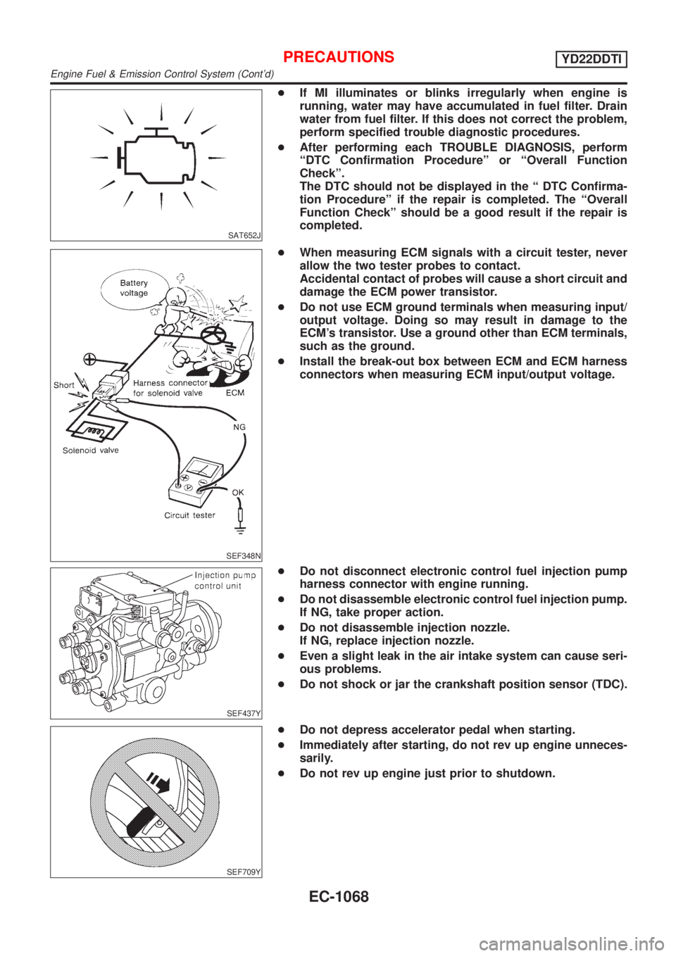
+If MI illuminates or blinks irregularly when engine is
running, water may have accumulated in fuel filter. Drain
water from fuel filter. If this does not correct the problem,
perform specified trouble diagnostic procedures.
+After performing each TROUBLE DIAGNOSIS, perform
ªDTC Confirmation Procedureº or ªOverall Function
Checkº.
The DTC should not be displayed in the ª DTC Confirma-
tion Procedureº if the repair is completed. The ªOverall
Function Checkº should be a good result if the repair is
completed.
SEF348N
+When measuring ECM signals with a circuit tester, never
allow the two tester probes to contact.
Accidental contact of probes will cause a short circuit and
damage the ECM power transistor.
+Do not use ECM ground terminals when measuring input/
output voltage. Doing so may result in damage to the
ECM's transistor. Use a ground other than ECM terminals,
such as the ground.
+Install the break-out box between ECM and ECM harness
connectors when measuring ECM input/output voltage.
SEF437Y
+Do not disconnect electronic control fuel injection pump
harness connector with engine running.
+Do not disassemble electronic control fuel injection pump.
If NG, take proper action.
+Do not disassemble injection nozzle.
If NG, replace injection nozzle.
+Even a slight leak in the air intake system can cause seri-
ous problems.
+Do not shock or jar the crankshaft position sensor (TDC).
SEF709Y
+Do not depress accelerator pedal when starting.
+Immediately after starting, do not rev up engine unneces-
sarily.
+Do not rev up engine just prior to shutdown.
PRECAUTIONSYD22DDTI
Engine Fuel & Emission Control System (Cont'd)
EC-1068
Page 1519 of 3051
Fuel Filter
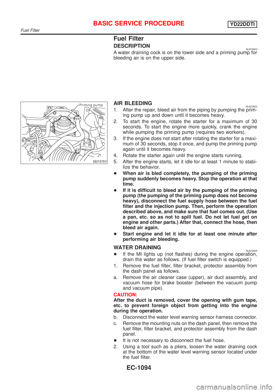
DESCRIPTIONNLEC0623A water draining cock is on the lower side and a priming pump for
bleeding air is on the upper side.
SEF375Y
AIR BLEEDINGNLEC06241. After the repair, bleed air from the piping by pumping the prim-
ing pump up and down until it becomes heavy.
2. To start the engine, rotate the starter for a maximum of 30
seconds. To start the engine more quickly, crank the engine
while pumping the priming pump (requires two workers).
3. If the engine does not start after rotating the starter for a maxi-
mum of 30 seconds, stop it once, and pump the priming pump
again until it becomes heavy.
4. Rotate the starter again until the engine starts running.
5. After the engine starts, let it idle for at least 1 minute to stabi-
lize the behavior.
+When air is bled completely, the pumping of the priming
pump suddenly becomes heavy. Stop the operation at that
time.
+If it is difficult to bleed air by the pumping of the priming
pump (the pumping of the priming pump does not become
heavy), disconnect the fuel supply hose between the fuel
filter and the injection pump. Then, perform the operation
described above, and make sure that fuel comes out. (Use
a pan, etc. so as not to spill fuel. Do not let fuel get on
engine and other parts.) After that, connect the hose, then
bleed air again.
+Start engine and let it idle for at least one minute after
performing air bleeding.
WATER DRAININGNLEC0625+If the MI lights up (not flashes) during the engine operation,
drain the water as follows. (If fuel filter switch is equipped.)
1. Remove the fuel filter, filter bracket, protector assembly from
the dash panel as follows.
a. Remove the air cleaner case (upper), air duct assembly, and
vacuum hose for brake booster (between the vacuum pump
and vacuum pipe).
CAUTION:
After the duct is removed, cover the opening with gum tape,
etc. to prevent foreign object from getting into the engine
during the operation.
b. Disconnect the water level warning sensor harness connector.
c. Remove the mounting nuts on the dash panel, then remove the
fuel filter, filter bracket, and protector assembly from the dash
panel.
+It is not necessary to disconnect the fuel hose.
2. Using a tool such as a pliers, loosen the water draining cock
at the bottom of the water level warning sensor located under
the fuel filter.
BASIC SERVICE PROCEDUREYD22DDTI
Fuel Filter
EC-1094
Page 1520 of 3051
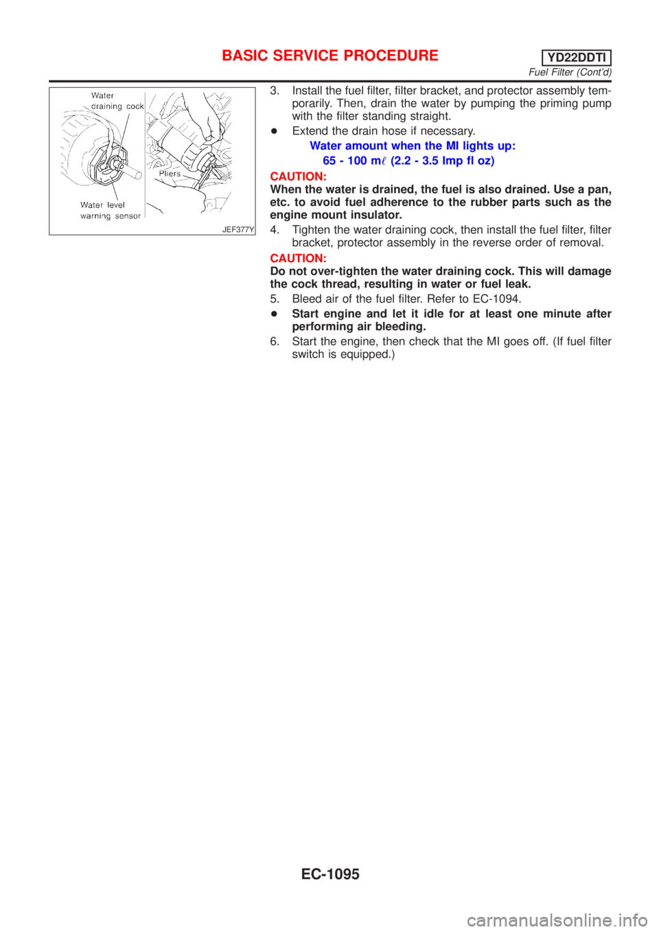
JEF377Y
3. Install the fuel filter, filter bracket, and protector assembly tem-
porarily. Then, drain the water by pumping the priming pump
with the filter standing straight.
+Extend the drain hose if necessary.
Water amount when the MI lights up:
65 - 100 m!(2.2 - 3.5 Imp fl oz)
CAUTION:
When the water is drained, the fuel is also drained. Use a pan,
etc. to avoid fuel adherence to the rubber parts such as the
engine mount insulator.
4. Tighten the water draining cock, then install the fuel filter, filter
bracket, protector assembly in the reverse order of removal.
CAUTION:
Do not over-tighten the water draining cock. This will damage
the cock thread, resulting in water or fuel leak.
5. Bleed air of the fuel filter. Refer to EC-1094.
+Start engine and let it idle for at least one minute after
performing air bleeding.
6. Start the engine, then check that the MI goes off. (If fuel filter
switch is equipped.)
BASIC SERVICE PROCEDUREYD22DDTI
Fuel Filter (Cont'd)
EC-1095
Page 1627 of 3051
![NISSAN ALMERA TINO 2001 Service Repair Manual TERMI-
NAL
NO.WIRE
COLORITEM CONDITION DATA(DC Voltage)
221 LG/B Cooling fan relay (High)[Engine is running]
+Cooling fans are not operating
+Cooling fans are operating at low speedBATTERY VOLTAGE
(11 NISSAN ALMERA TINO 2001 Service Repair Manual TERMI-
NAL
NO.WIRE
COLORITEM CONDITION DATA(DC Voltage)
221 LG/B Cooling fan relay (High)[Engine is running]
+Cooling fans are not operating
+Cooling fans are operating at low speedBATTERY VOLTAGE
(11](/manual-img/5/57352/w960_57352-1626.png)
TERMI-
NAL
NO.WIRE
COLORITEM CONDITION DATA(DC Voltage)
221 LG/B Cooling fan relay (High)[Engine is running]
+Cooling fans are not operating
+Cooling fans are operating at low speedBATTERY VOLTAGE
(11 - 14V)
[Engine is running]
+Cooling fans are operating at high speedApproximately 0.1V
On Board Diagnosis LogicNLEC0663This diagnosis continuously monitors the engine coolant temperature.
If the cooling fan or another component in the cooling system malfunctions, engine coolant temperature will
rise.
When the engine coolant temperature reaches an abnormally high temperature condition, a malfunction is
indicated.
DTC Malfunction is detected when ... Check Items (Possible Cause)
P1217
0208+Cooling fan does not operate properly (Overheat).
+Cooling fan system does not operate properly
(Overheat).
+Engine coolant was not added to the system using
the proper filling method.+Harness or connectors
(The cooling fan circuit is open or shorted.)
+Cooling fan
+Radiator hose
+Radiator
+Radiator cap
+Water pump
+Thermostat
+Engine coolant temperature sensor
For more information, refer to ªMAIN 12 CAUSES OF
OVERHEATINGº, EC-1217.
CAUTION:
When a malfunction is indicated, be sure to replace the coolant following the procedure in the LC-59,
ªChanging Engine Coolantº. Also, replace the engine oil.
1) Fill radiator with coolant up to specified level with a filling speed of 2 liters per minute. Be sure
to use coolant with the proper mixture ratio. Refer to MA-22, ªEngine Coolant Mixture Ratioº.
2) After refilling coolant, run engine to ensure that no water-flow noise is emitted.
DTC P1217 OVER HEATYD22DDTI
ECM Terminals and Reference Value (Cont'd)
EC-1202
Page 1634 of 3051
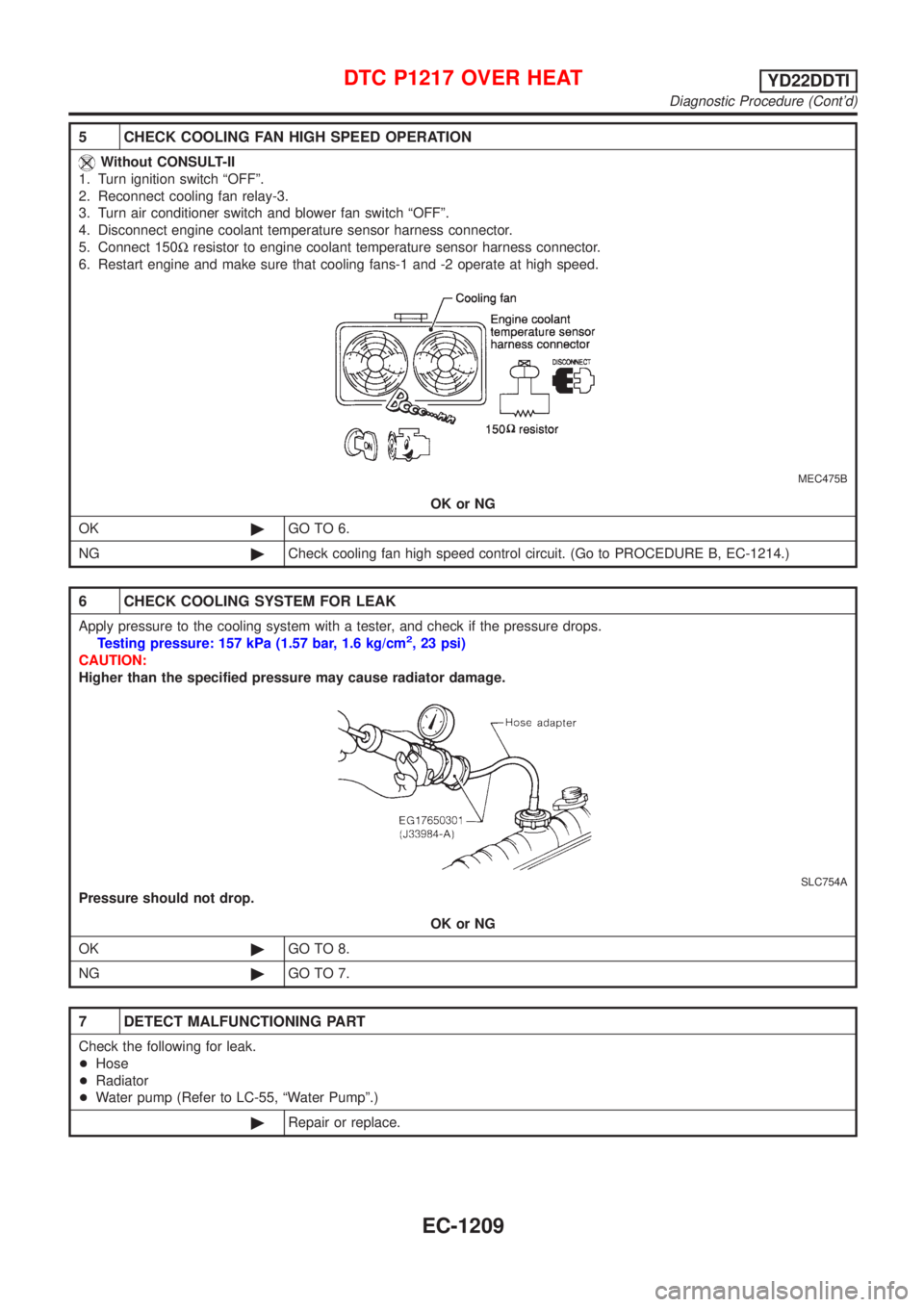
5 CHECK COOLING FAN HIGH SPEED OPERATION
Without CONSULT-II
1. Turn ignition switch ªOFFº.
2. Reconnect cooling fan relay-3.
3. Turn air conditioner switch and blower fan switch ªOFFº.
4. Disconnect engine coolant temperature sensor harness connector.
5. Connect 150Wresistor to engine coolant temperature sensor harness connector.
6. Restart engine and make sure that cooling fans-1 and -2 operate at high speed.
MEC475B
OK or NG
OK©GO TO 6.
NG©Check cooling fan high speed control circuit. (Go to PROCEDURE B, EC-1214.)
6 CHECK COOLING SYSTEM FOR LEAK
Apply pressure to the cooling system with a tester, and check if the pressure drops.
Testing pressure: 157 kPa (1.57 bar, 1.6 kg/cm2, 23 psi)
CAUTION:
Higher than the specified pressure may cause radiator damage.
SLC754A
Pressure should not drop.
OK or NG
OK©GO TO 8.
NG©GO TO 7.
7 DETECT MALFUNCTIONING PART
Check the following for leak.
+Hose
+Radiator
+Water pump (Refer to LC-55, ªWater Pumpº.)
©Repair or replace.
DTC P1217 OVER HEATYD22DDTI
Diagnostic Procedure (Cont'd)
EC-1209
Page 1648 of 3051
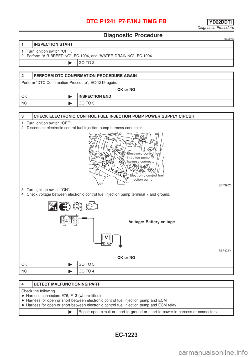
Diagnostic ProcedureNLEC0733
1 INSPECTION START
1. Turn ignition switch ªOFFº.
2. Perform ªAIR BREEDINGº, EC-1094, and ªWATER DRAININGº, EC-1094.
©GO TO 2.
2 PERFORM DTC CONFIRMATION PROCEDURE AGAIN
Perform ªDTC Confirmation Procedureº, EC-1219 again.
OK or NG
OK©INSPECTION END
NG©GO TO 3.
3 CHECK ELECTRONIC CONTROL FUEL INJECTION PUMP POWER SUPPLY CIRCUIT
1. Turn ignition switch ªOFFº.
2. Disconnect electronic control fuel injection pump harness connector.
SEF390Y
3. Turn ignition switch ªONº.
4. Check voltage between electronic control fuel injection pump terminal 7 and ground.
SEF438Y
OK or NG
OK©GO TO 5.
NG©GO TO 4.
4 DETECT MALFUNCTIONING PART
Check the following.
+Harness connectors E76, F13 (where fitted)
+Harness for open or short between electronic control fuel injection pump and ECM
+Harness for open or short between electronic control fuel injection pump and ECM relay
©Repair open circuit or short to ground or short to power in harness or connectors.
DTC P1241 P7´F/INJ TIMG FBYD22DDTI
Diagnostic Procedure
EC-1223
Page 2260 of 3051
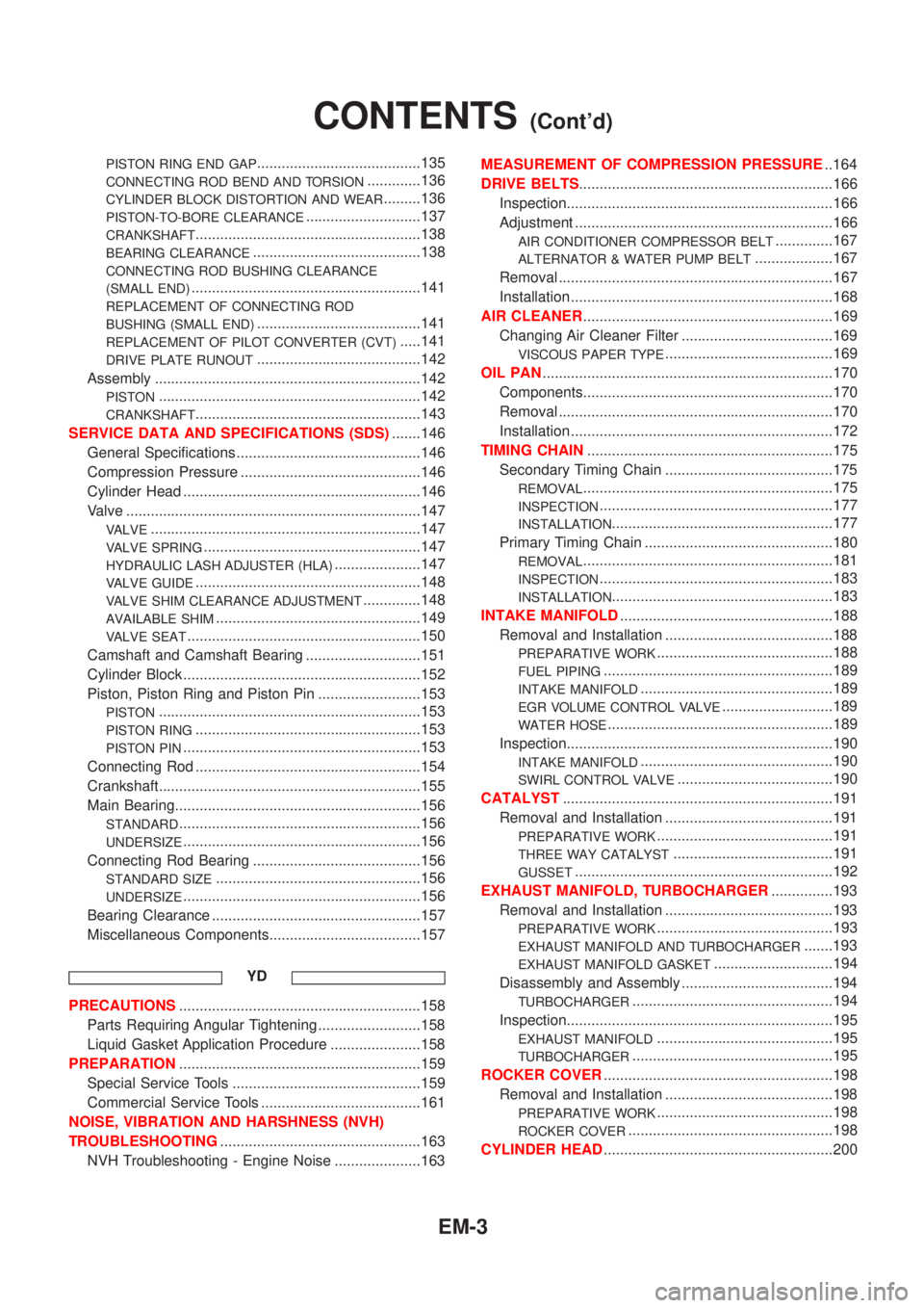
PISTON RING END GAP........................................135
CONNECTING ROD BEND AND TORSION.............136
CYLINDER BLOCK DISTORTION AND WEAR.........136
PISTON-TO-BORE CLEARANCE............................137
CRANKSHAFT.......................................................138
BEARING CLEARANCE.........................................138
CONNECTING ROD BUSHING CLEARANCE
(SMALL END)
........................................................141
REPLACEMENT OF CONNECTING ROD
BUSHING (SMALL END)
........................................141
REPLACEMENT OF PILOT CONVERTER (CVT).....141
DRIVE PLATE RUNOUT........................................142
Assembly .................................................................142
PISTON................................................................142
CRANKSHAFT.......................................................143
SERVICE DATA AND SPECIFICATIONS (SDS).......146
General Specifications .............................................146
Compression Pressure ............................................146
Cylinder Head ..........................................................146
Valve ........................................................................147
VALVE..................................................................147
VALVE SPRING.....................................................147
HYDRAULIC LASH ADJUSTER (HLA).....................147
VALVE GUIDE.......................................................148
VALVE SHIM CLEARANCE ADJUSTMENT..............148
AVAILABLE SHIM..................................................149
VALVE SEAT.........................................................150
Camshaft and Camshaft Bearing ............................151
Cylinder Block ..........................................................152
Piston, Piston Ring and Piston Pin .........................153
PISTON................................................................153
PISTON RING.......................................................153
PISTON PIN..........................................................153
Connecting Rod .......................................................154
Crankshaft................................................................155
Main Bearing............................................................156
STANDARD...........................................................156
UNDERSIZE..........................................................156
Connecting Rod Bearing .........................................156
STANDARD SIZE..................................................156
UNDERSIZE..........................................................156
Bearing Clearance ...................................................157
Miscellaneous Components.....................................157
YD
PRECAUTIONS...........................................................158
Parts Requiring Angular Tightening .........................158
Liquid Gasket Application Procedure ......................158
PREPARATION...........................................................159
Special Service Tools ..............................................159
Commercial Service Tools .......................................161
NOISE, VIBRATION AND HARSHNESS (NVH)
TROUBLESHOOTING.................................................163
NVH Troubleshooting - Engine Noise .....................163MEASUREMENT OF COMPRESSION PRESSURE..164
DRIVE BELTS..............................................................166
Inspection.................................................................166
Adjustment ...............................................................166
AIR CONDITIONER COMPRESSOR BELT..............167
ALTERNATOR & WATER PUMP BELT...................167
Removal ...................................................................167
Installation ................................................................168
AIR CLEANER.............................................................169
Changing Air Cleaner Filter .....................................169
VISCOUS PAPER TYPE.........................................169
OIL PAN.......................................................................170
Components.............................................................170
Removal ...................................................................170
Installation ................................................................172
TIMING CHAIN............................................................175
Secondary Timing Chain .........................................175
REMOVAL.............................................................175
INSPECTION.........................................................177
INSTALLATION......................................................177
Primary Timing Chain ..............................................180
REMOVAL.............................................................181
INSPECTION.........................................................183
INSTALLATION......................................................183
INTAKE MANIFOLD....................................................188
Removal and Installation .........................................188
PREPARATIVE WORK...........................................188
FUEL PIPING........................................................189
INTAKE MANIFOLD...............................................189
EGR VOLUME CONTROL VALVE...........................189
WATER HOSE.......................................................189
Inspection.................................................................190
INTAKE MANIFOLD...............................................190
SWIRL CONTROL VALVE......................................190
CATALYST..................................................................191
Removal and Installation .........................................191
PREPARATIVE WORK...........................................191
THREE WAY CATALYST.......................................191
GUSSET...............................................................192
EXHAUST MANIFOLD, TURBOCHARGER...............193
Removal and Installation .........................................193
PREPARATIVE WORK...........................................193
EXHAUST MANIFOLD AND TURBOCHARGER.......193
EXHAUST MANIFOLD GASKET.............................194
Disassembly and Assembly .....................................194
TURBOCHARGER.................................................194
Inspection.................................................................195
EXHAUST MANIFOLD...........................................195
TURBOCHARGER.................................................195
ROCKER COVER........................................................198
Removal and Installation .........................................198
PREPARATIVE WORK...........................................198
ROCKER COVER..................................................198
CYLINDER HEAD........................................................200
CONTENTS(Cont'd)
EM-3
Page 2267 of 3051
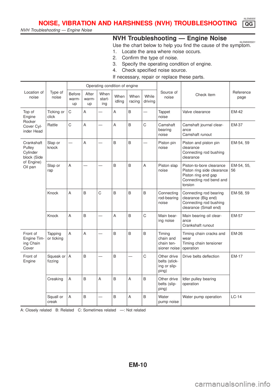
NLEM0005
NVH Troubleshooting Ð Engine NoiseNLEM0005S01Use the chart below to help you find the cause of the symptom.
1. Locate the area where noise occurs.
2. Confirm the type of noise.
3. Specify the operating condition of engine.
4. Check specified noise source.
If necessary, repair or replace these parts.
Location of
noiseType of
noiseOperating condition of engine
Source of
noiseCheck itemReference
page Before
warm-
upAfter
warm-
upWhen
start-
ingWhen
idlingWhen
racingWhile
driving
To p o f
Engine
Rocker
Cover Cyl-
inder HeadTicking or
clickC A Ð A B Ð Tappet
noiseValve clearance EM-42
Rattle C A Ð A B C Camshaft
bearing
noiseCamshaft journal clear-
ance
Camshaft runoutEM-37
Crankshaft
Pulley
Cylinder
block (Side
of Engine)
Oil panSlap or
knockÐ A Ð B B Ð Piston pin
noisePiston and piston pin
clearance
Connecting rod bushing
clearanceEM-54, 59
Slap or
rapA Ð Ð B B A Piston slap
noisePiston-to-bore clearance
Piston ring side clearance
Piston ring end gap
Connecting rod bend and
torsionEM-54, 55,
56
Knock A B CB B B Connecting
rod-bearing
noiseConnecting rod bearing
clearance (Big end)
Connecting rod bushing
clearance (Small end)EM-58, 59
Knock A B Ð A B C Main bear-
ing noiseMain bearing oil clear-
ance
Crankshaft runoutEM-57
Front of
Engine Tim-
ing Chain
CoverTapping
or tickingAAÐBBBTiming
chain and
chain ten-
sioner noiseTiming chain cracks and
wear
Timing chain tensioner
operationEM-26
Front of
EngineSqueak or
fizzingA B Ð B Ð C Other drive
belts (stick-
ing or slip-
ping)Drive belts deflection EM-17
CreakingABABABOther drive
belts (slip-
ping)Idler pulley bearing
operation
Squall or
creakABÐBABWater
pump noiseWater pump operation LC-14
A: Closely related B: Related C: Sometimes related Ð: Not related
NOISE, VIBRATION AND HARSHNESS (NVH) TROUBLESHOOTINGQG
NVH Troubleshooting Ð Engine Noise
EM-10