Page 2269 of 3051
Removal and InstallationNLEM0006
YEM002
1. Oil pressure switch
2. EGR valve
3. EGR tube
4. Air relief plug
5. Intake manifold6. Intake manifold upper support
7. Intake manifold lower supports
8. Oil filter
9. Thermostat
10. Water pump11. Water pump pulley
12. EGR solenoid valve
13. EGR guide tube
14. EGR gas temperature sensor
OUTER COMPONENT PARTSQG
Removal and Installation
EM-12
Page 2283 of 3051
SEM104G
27. Remove RH engine mounting bracket.
28. Remove idler pulley and bracket.
SEM883F
29. Remove water pump pulley and water pump.
30. Remove front cover bolts and front cover as shown.
H1: Located on water pump
H2: Located on power steering pump adjusting bar
+Inspect for oil leakage at front oil seal. Replace seal if oil leak
is present.
SEM884F
SEM897F
31. Remove timing chain.
32. Remove oil pump drive spacer.
33. Remove chain guides.
34. Remove crankshaft sprocket.
35. Remove O-rings from cylinder block and front cover.
SEM885F
InspectionNLEM0106Check for cracks and excessive wear at roller links. Replace
if necessary.
TIMING CHAINQG
Removal (Cont'd)
EM-26
Page 2285 of 3051
SEM519G
6. Install camshaft sprocket bolts and tighten them to correct
torque.
+Apply new engine oil to bolt threads and seat surface.
SEM520G
7. Install chain tensioner.
+Before installing chain tensioner, insert a suitable pin into
pin hole of chain tensioner.
+After installing chain tensioner, remove the pin.
8. Install timing chain guide.
SEM893F
9. Install O-rings to cylinder block.
SEM894F
10. Before installing front cover, remove all traces of liquid gasket
from mating surface using a scraper.
+Also remove traces of liquid gasket from mating surface of
cylinder block.
SEM895F
11. Apply a continuous bead of liquid gasket to mating surface of
front cover.
+Check alignment of mating marks on chain and crankshaft
sprocket.
+Align oil drive spacer with oil pump.
+Place timing chain to the side of chain guide. This pre-
vents the chain from making contact with water seal area
of front cover.
TIMING CHAINQG
Installation (Cont'd)
EM-28
Page 2286 of 3051

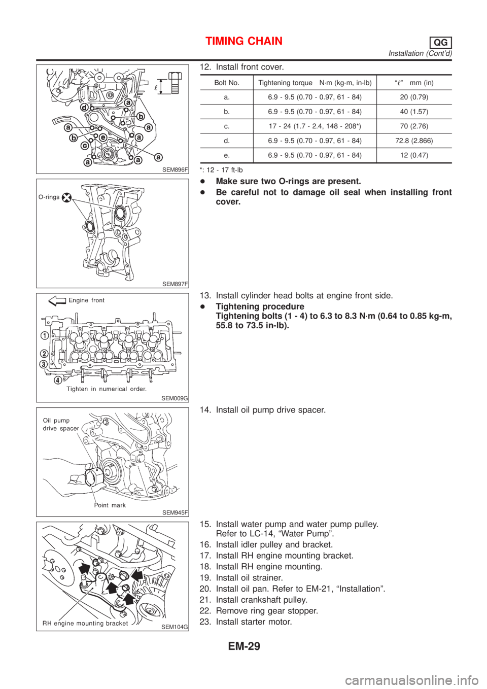
SEM896F
12. Install front cover.
Bolt No. Tightening torque N´m (kg-m, in-lb) ª!º mm (in)
a. 6.9 - 9.5 (0.70 - 0.97, 61 - 84) 20 (0.79)
b. 6.9 - 9.5 (0.70 - 0.97, 61 - 84) 40 (1.57)
c. 17 - 24 (1.7 - 2.4, 148 - 208*) 70 (2.76)
d. 6.9 - 9.5 (0.70 - 0.97, 61 - 84) 72.8 (2.866)
e. 6.9 - 9.5 (0.70 - 0.97, 61 - 84) 12 (0.47)
*: 12 - 17 ft-lb
SEM897F
+Make sure two O-rings are present.
+Be careful not to damage oil seal when installing front
cover.
SEM009G
13. Install cylinder head bolts at engine front side.
+Tightening procedure
Tightening bolts (1 - 4) to 6.3 to 8.3 N´m (0.64 to 0.85 kg-m,
55.8 to 73.5 in-lb).
SEM945F
14. Install oil pump drive spacer.
SEM104G
15. Install water pump and water pump pulley.
Refer to LC-14, ªWater Pumpº.
16. Install idler pulley and bracket.
17. Install RH engine mounting bracket.
18. Install RH engine mounting.
19. Install oil strainer.
20. Install oil pan. Refer to EM-21, ªInstallationº.
21. Install crankshaft pulley.
22. Remove ring gear stopper.
23. Install starter motor.
TIMING CHAINQG
Installation (Cont'd)
EM-29
Page 2338 of 3051

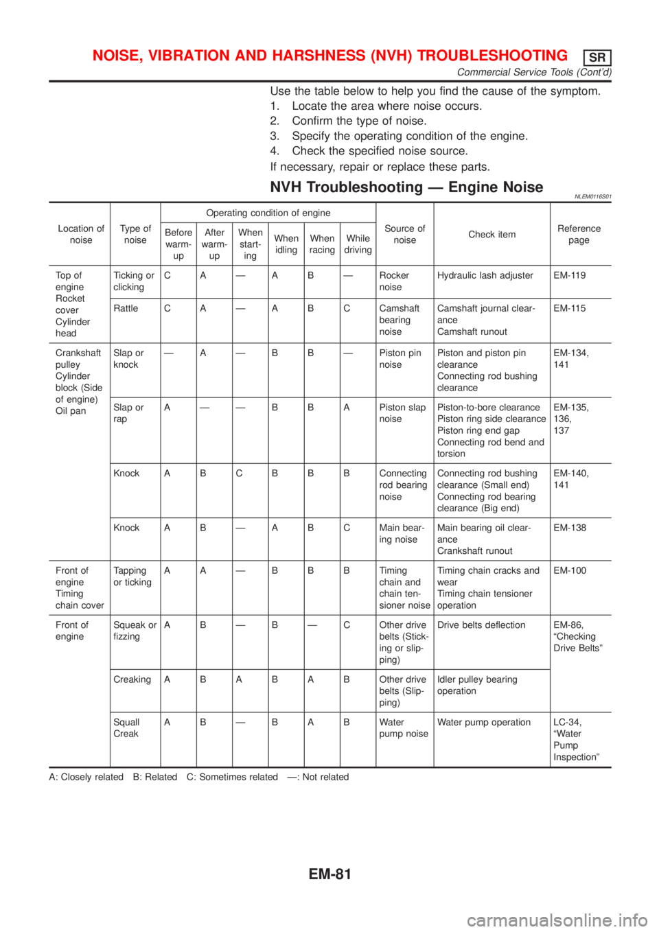
Use the table below to help you find the cause of the symptom.
1. Locate the area where noise occurs.
2. Confirm the type of noise.
3. Specify the operating condition of the engine.
4. Check the specified noise source.
If necessary, repair or replace these parts.
NVH Troubleshooting Ð Engine NoiseNLEM0116S01
Location of
noiseType of
noiseOperating condition of engine
Source of
noiseCheck itemReference
page Before
warm-
upAfter
warm-
upWhen
start-
ingWhen
idlingWhen
racingWhile
driving
To p o f
engine
Rocket
cover
Cylinder
headTicking or
clickingC A Ð A B Ð Rocker
noiseHydraulic lash adjuster EM-119
Rattle C A Ð A B C Camshaft
bearing
noiseCamshaft journal clear-
ance
Camshaft runoutEM-115
Crankshaft
pulley
Cylinder
block (Side
of engine)
Oil panSlap or
knockÐ A Ð B B Ð Piston pin
noisePiston and piston pin
clearance
Connecting rod bushing
clearanceEM-134,
141
Slap or
rapA Ð Ð B B A Piston slap
noisePiston-to-bore clearance
Piston ring side clearance
Piston ring end gap
Connecting rod bend and
torsionEM-135,
136,
137
Knock A B CB B B Connecting
rod bearing
noiseConnecting rod bushing
clearance (Small end)
Connecting rod bearing
clearance (Big end)EM-140,
141
Knock A B Ð A B C Main bear-
ing noiseMain bearing oil clear-
ance
Crankshaft runoutEM-138
Front of
engine
Timing
chain coverTapping
or tickingAAÐBBBTiming
chain and
chain ten-
sioner noiseTiming chain cracks and
wear
Timing chain tensioner
operationEM-100
Front of
engineSqueak or
fizzingA B Ð B Ð C Other drive
belts (Stick-
ing or slip-
ping)Drive belts deflection EM-86,
ªChecking
Drive Beltsº
CreakingABABABOther drive
belts (Slip-
ping)Idler pulley bearing
operation
Squall
CreakABÐBABWater
pump noiseWater pump operation LC-34,
ªWater
Pump
Inspectionº
A: Closely related B: Related C: Sometimes related Ð: Not related
NOISE, VIBRATION AND HARSHNESS (NVH) TROUBLESHOOTINGSR
Commercial Service Tools (Cont'd)
EM-81
Page 2339 of 3051
Removal and InstallationNLEM0117
NEM351
1. Oil filler cap
2. Rocker cover
3. PCV valve
4. Distributor
5. Intake manifold supports6. Knock sensor
7. Oil filter
8. Oil filter bracket
9. Water inlet
10. Thermostat housing11. Water pipe assembly
12. Thermostat
13. Starter motor
14. Power steering oil pump adjusting
bar
15. Power steering oil pump bracket
OUTER COMPONENT PARTSSR
Removal and Installation
EM-82
Page 2354 of 3051
CAUTION:
+After removing timing chain, do not turn crankshaft and
camshaft separately, or valves will strike piston heads.
+When installing chain tensioner, oil seals, or other sliding
parts, lubricate contacting surfaces with new engine oil.
+Apply new engine oil to bolt threads and seat surfaces
when installing camshaft sprocket and crankshaft pulley.
RemovalNLEM01261. Remove engine under cover.
2. Remove front RH wheel and engine side cover.
3. Drain coolant by removing cylinder block drain plug and lower
radiator hose. Refer to LC-38, ªChanging Engine Coolantº.
4. Remove drive belts and water pump pulley.
5. Disconnect the following parts:
+Vacuum hoses
+Wires
+Harness
+Connectors
SEM029G
6. Remove rocker cover bolts in numerical order.
7. Remove rocker cover.
SEM287G
8. Remove cylinder head outside bolts.
TIMING CHAINSR
Components (Cont'd)
EM-97
Page 2361 of 3051

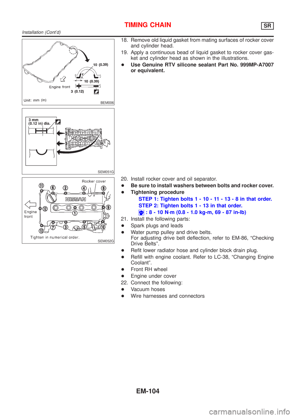
BEM006
SEM051G
18. Remove old liquid gasket from mating surfaces of rocker cover
and cylinder head.
19. Apply a continuous bead of liquid gasket to rocker cover gas-
ket and cylinder head as shown in the illustrations.
+Use Genuine RTV silicone sealant Part No. 999MP-A7007
or equivalent.
SEM052G
20. Install rocker cover and oil separator.
+Be sure to install washers between bolts and rocker cover.
+Tightening procedure
STEP 1: Tighten bolts1-10-11-13-8inthat order.
STEP 2: Tighten bolts1-13inthat order.
:8-10N´m(0.8 - 1.0 kg-m, 69 - 87 in-lb)
21. Install the following parts:
+Spark plugs and leads
+Water pump pulley and drive belts.
For adjusting drive belt deflection, refer to EM-86, ªChecking
Drive Beltsº.
+Refit lower radiator hose and cylinder block drain plug.
+Refill with engine coolant. Refer to LC-38, ªChanging Engine
Coolantº.
+Front RH wheel
+Engine under cover
22. Connect the following:
+Vacuum hoses
+Wire harnesses and connectors
TIMING CHAINSR
Installation (Cont'd)
EM-104