Page 1075 of 3051
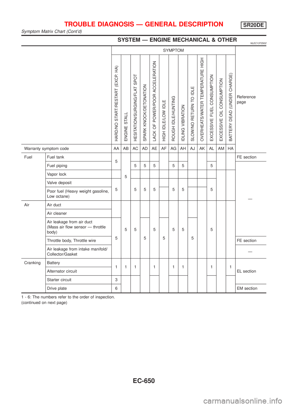
SYSTEM Ð ENGINE MECHANICAL & OTHERNLEC1372S02
SYMPTOM
Reference
page
HARD/NO START/RESTART (EXCP. HA)
ENGINE STALL
HESITATION/SURGING/FLAT SPOT
SPARK KNOCK/DETONATION
LACK OF POWER/POOR ACCELERATION
HIGH IDLE/LOW IDLE
ROUGH IDLE/HUNTING
IDLING VIBRATION
SLOW/NO RETURN TO IDLE
OVERHEATS/WATER TEMPERATURE HIGH
EXCESSIVE FUEL CONSUMPTION
EXCESSIVE OIL CONSUMPTION
BATTERY DEAD (UNDER CHARGE)
Warranty symptom code AA AB AC AD AE AF AG AH AJ AK AL AM HA
Fuel Fuel tank
5
5FE section
Fuel piping 5 5 5 5 5 5
Ð Vapor lock
Valve deposit
5 555 55 5
Poor fuel (Heavy weight gasoline,
Low octane)
Air Air duct
55555 5 Air cleaner
Air leakage from air duct
(Mass air flow sensor Ð throttle
body)
5555
Throttle body, Throttle wireFE section
Air leakage from intake manifold/
Collector/GasketÐ
Cranking Battery
111111 11
EL section Alternator circuit
Starter circuit 3
Drive plate 6 EM section
1 - 6: The numbers refer to the order of inspection.
(continued on next page)
TROUBLE DIAGNOSIS Ð GENERAL DESCRIPTIONSR20DE
Symptom Matrix Chart (Cont'd)
EC-650
Page 1076 of 3051
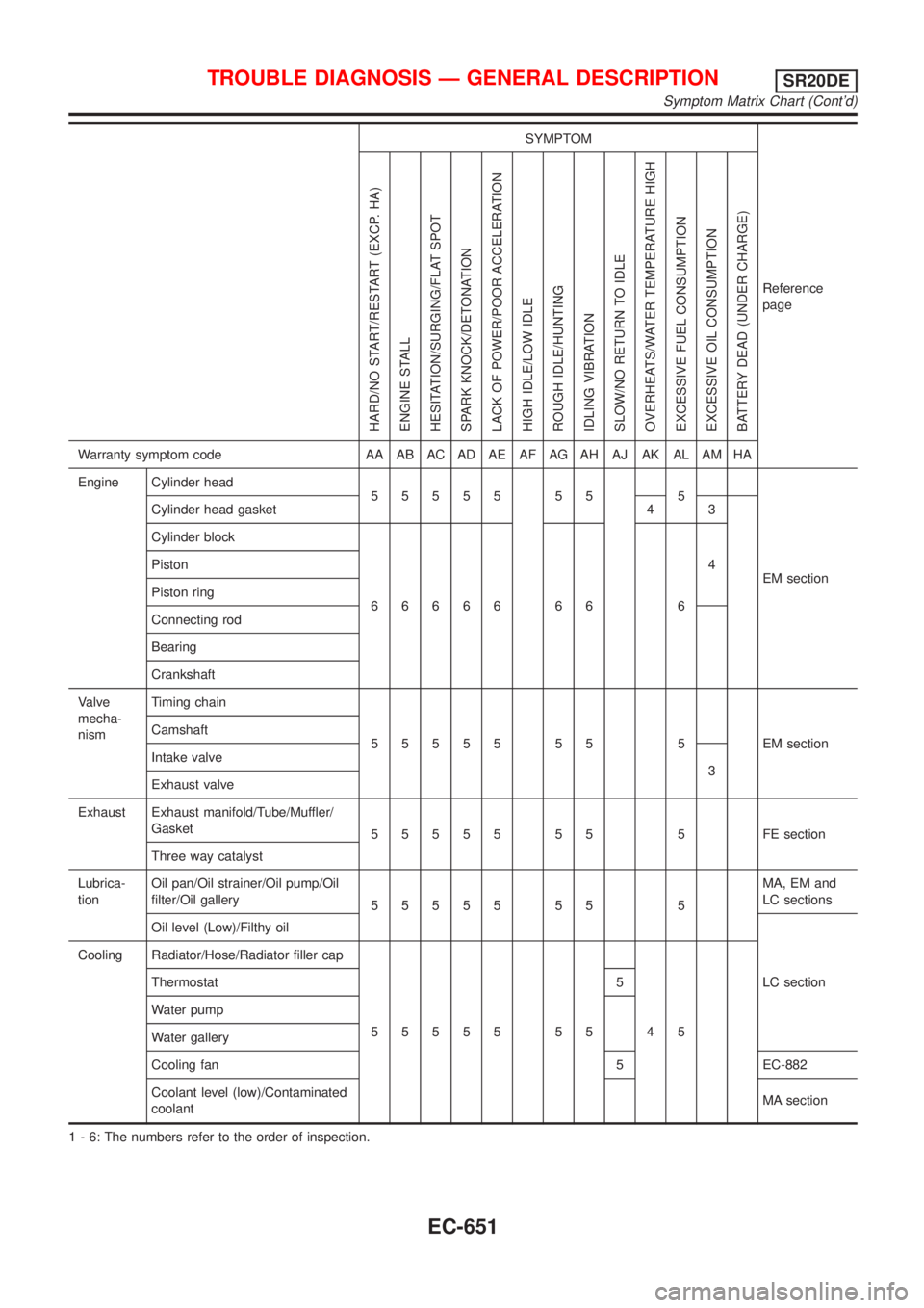
SYMPTOM
Reference
page
HARD/NO START/RESTART (EXCP. HA)
ENGINE STALL
HESITATION/SURGING/FLAT SPOT
SPARK KNOCK/DETONATION
LACK OF POWER/POOR ACCELERATION
HIGH IDLE/LOW IDLE
ROUGH IDLE/HUNTING
IDLING VIBRATION
SLOW/NO RETURN TO IDLE
OVERHEATS/WATER TEMPERATURE HIGH
EXCESSIVE FUEL CONSUMPTION
EXCESSIVE OIL CONSUMPTION
BATTERY DEAD (UNDER CHARGE)
Warranty symptom code AA AB AC AD AE AF AG AH AJ AK AL AM HA
Engine Cylinder head
55555 55 5
EM section Cylinder head gasket 4 3
Cylinder block
66666 66 64 Piston
Piston ring
Connecting rod
Bearing
Crankshaft
Valve
mecha-
nismTiming chain
55555 55 5 EMsection Camshaft
Intake valve
3
Exhaust valve
Exhaust Exhaust manifold/Tube/Muffler/
Gasket
55555 55 5 FEsection
Three way catalyst
Lubrica-
tionOil pan/Oil strainer/Oil pump/Oil
filter/Oil gallery
55555 55 5MA, EM and
LC sections
Oil level (Low)/Filthy oil
LC section Cooling Radiator/Hose/Radiator filler cap
55555 55 45 Thermostat 5
Water pump
Water gallery
Cooling fan 5 EC-882
Coolant level (low)/Contaminated
coolantMA section
1 - 6: The numbers refer to the order of inspection.
TROUBLE DIAGNOSIS Ð GENERAL DESCRIPTIONSR20DE
Symptom Matrix Chart (Cont'd)
EC-651
Page 1261 of 3051
DTC No. Malfunction is detected when ... Check Items (Possible Cause)
P0400+No EGR flow is detected under conditions that call for
EGR.+Harness or connectors
(EGR volume control valve circuit is open or
shorted.)
+EGR volume control valve stuck closed
+Dead (Weak) battery
+EGR passage clogged
+EGR temperature sensor and circuit
+Exhaust gas leaks
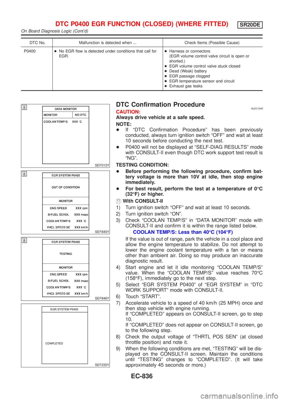
SEF013Y
SEF845Y
SEF846Y
SEF235Y
DTC Confirmation ProcedureNLEC1549CAUTION:
Always drive vehicle at a safe speed.
NOTE:
+If ªDTC Confirmation Procedureº has been previously
conducted, always turn ignition switch ªOFFº and wait at least
10 seconds before conducting the next test.
+P0400 will not be displayed at ªSELF-DIAG RESULTSº mode
with CONSULT-II even though DTC work support test result is
ªNGº.
TESTING CONDITION:
+Before performing the following procedure, confirm bat-
tery voltage is more than 10V at idle, then stop engine
immediately.
+For best result, perform the test at a temperature of 0ÉC
(32ÉF) or higher.
With CONSULT-II
1) Turn ignition switch ªOFFº and wait at least 10 seconds.
2) Turn ignition switch ªONº.
3) Check ªCOOLAN TEMP/Sº in ªDATA MONITORº mode with
CONSULT-II and confirm it is within the range listed below.
COOLAN TEMP/S: Less than 40ÉC (104ÉF)
If the value is out of range, park the vehicle in a cool place and
allow the engine temperature to stabilize. Do not attempt to
lower the engine coolant temperature with a fan or means
other than ambient air. Doing so may produce an inaccurate
diagnostic result.
4) Start engine and let it idle monitoring ªCOOLAN TEMP/Sº
value. When the ªCOOLAN TEMP/Sº value reaches 70ÉC
(158ÉF), immediately go to the next step.
5) Select ªEGR SYSTEM P0400º of ªEGR SYSTEMº in ªDTC
WORK SUPPORTº mode with CONSULT-II.
6) Touch ªSTARTº.
7) Accelerate vehicle to a speed of 40 km/h (25 MPH) once and
then stop vehicle with engine running.
If ªCOMPLETEDº appears on CONSULT-II screen, go to step
10.
If ªCOMPLETEDº does not appear on CONSULT-II screen, go
to the following step.
8) Check the output voltage of ªTHRTL POS SENº (at closed
throttle position) and note it.
9) When the following conditions are met, ªTESTINGº will be dis-
played on the CONSULT-II screen. Maintain the conditions
until ªTESTINGº changes to ªCOMPLETEDº. (It will take
approximately 45 seconds or more.)
DTC P0400 EGR FUNCTION (CLOSED) (WHERE FITTED)SR20DE
On Board Diagnosis Logic (Cont'd)
EC-836
Page 1353 of 3051
System DescriptionNLEC1641The malfunction information related to CVT is transferred through the line (circuit) from TCM (Transmission
Control Module) to ECM. Therefore, be sure to erase the malfunction information such as DTC not only in TCM
(Transmission Control Module) but also ECM after the CVT related repair.
ECM Terminals and Reference ValueNLEC1642Specification data are reference values and are measured between each terminal and ground.
CAUTION:
Do not use ECM ground terminals when measuring input/output voltage. Doing so may result in dam-
age to the ECM's transistor. Use a ground other than ECM terminals, such as the ground.
TERMI-
NAL
NO.WIRE
COLORITEM CONDITION DATA (DC Voltage)
91 PU CVT check signal[Ignition switch ªONº]0 - Approximately 5V
On Board Diagnosis LogicNLEC1643
DTC No. Malfunction is detected when ... Check Items (Possible Cause)
P1605+An incorrect signal from TCM (Transmission Control
Module) is sent to ECM.+Harness or connectors
[The communication line circuit between ECM
and TCM (Transmission Control Module) is open
or shorted.]
+Dead (Weak) battery
+TCM (Transmission Control Module)
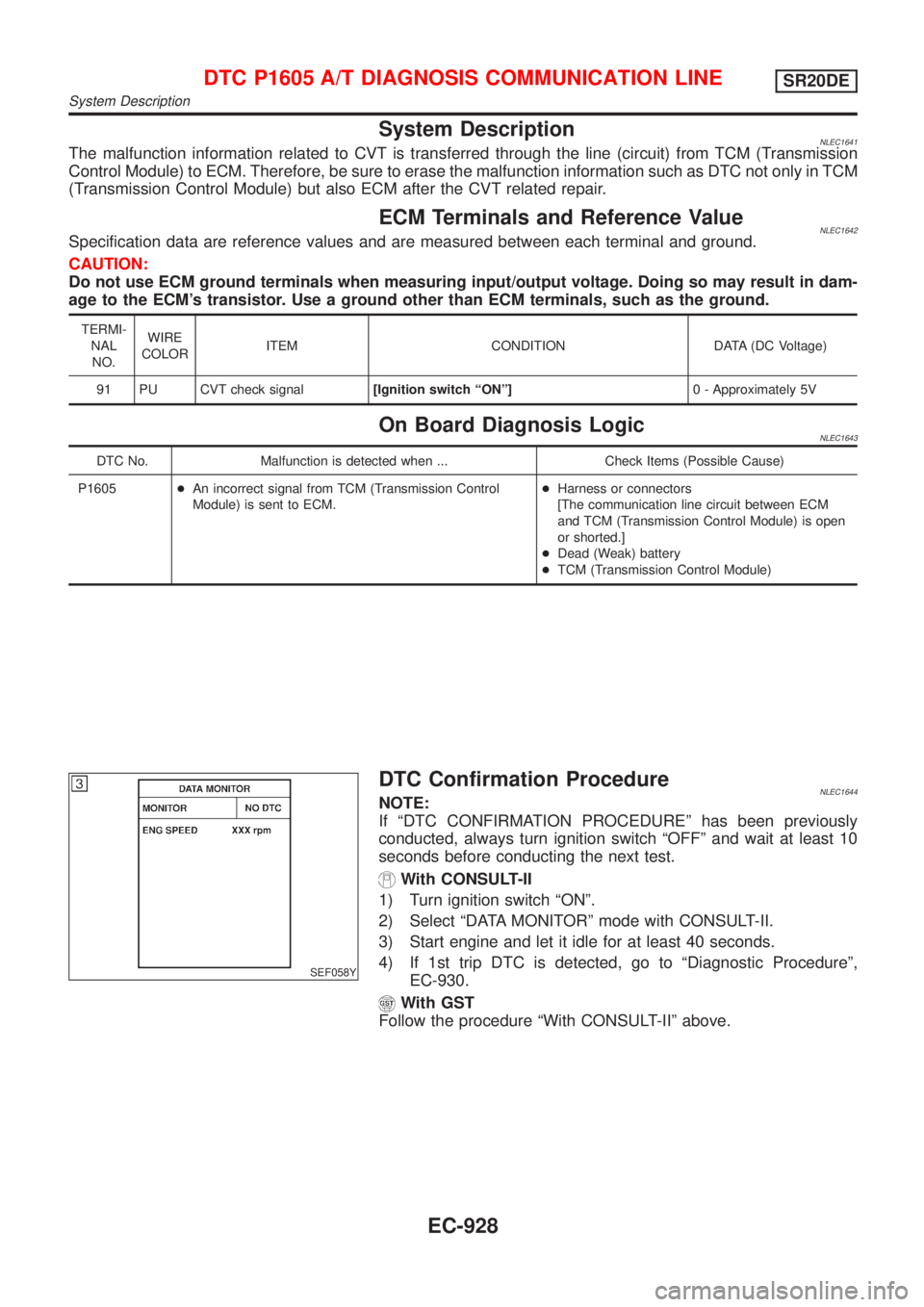
SEF058Y
DTC Confirmation ProcedureNLEC1644NOTE:
If ªDTC CONFIRMATION PROCEDUREº has been previously
conducted, always turn ignition switch ªOFFº and wait at least 10
seconds before conducting the next test.
With CONSULT-II
1) Turn ignition switch ªONº.
2) Select ªDATA MONITORº mode with CONSULT-II.
3) Start engine and let it idle for at least 40 seconds.
4) If 1st trip DTC is detected, go to ªDiagnostic Procedureº,
EC-930.
With GST
Follow the procedure ªWith CONSULT-IIº above.
DTC P1605 A/T DIAGNOSIS COMMUNICATION LINESR20DE
System Description
EC-928
Page 1542 of 3051
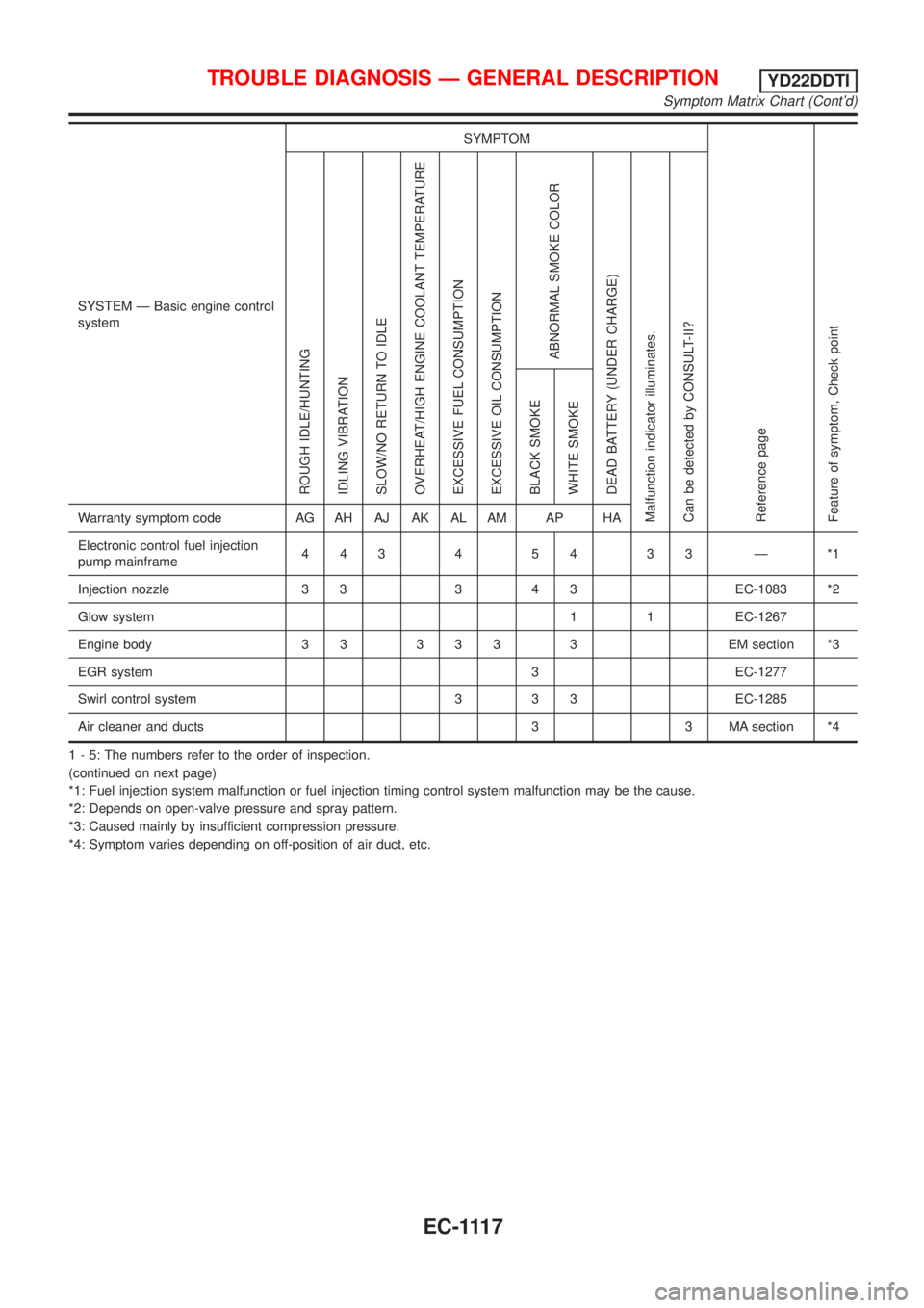
SYSTEM Ð Basic engine control
systemSYMPTOM
Reference page
Feature of symptom, Check pointROUGH IDLE/HUNTING
IDLING VIBRATION
SLOW/NO RETURN TO IDLE
OVERHEAT/HIGH ENGINE COOLANT TEMPERATURE
EXCESSIVE FUEL CONSUMPTION
EXCESSIVE OIL CONSUMPTION
ABNORMAL SMOKE COLOR
DEAD BATTERY (UNDER CHARGE)
Malfunction indicator illuminates.
Can be detected by CONSULT-II?BLACK SMOKE
WHITE SMOKEWarranty symptom code AG AH AJ AK AL AM AP HA
Electronic control fuel injection
pump mainframe44345433Ð*1
Injection nozzle 3 3 3 4 3 EC-1083 *2
Glow system 1 1 EC-1267
Engine body 3 3 3 3 3 3 EM section *3
EGR system 3 EC-1277
Swirl control system 3 3 3 EC-1285
Air cleaner and ducts 3 3 MA section *4
1 - 5: The numbers refer to the order of inspection.
(continued on next page)
*1: Fuel injection system malfunction or fuel injection timing control system malfunction may be the cause.
*2: Depends on open-valve pressure and spray pattern.
*3: Caused mainly by insufficient compression pressure.
*4: Symptom varies depending on off-position of air duct, etc.
TROUBLE DIAGNOSIS Ð GENERAL DESCRIPTIONYD22DDTI
Symptom Matrix Chart (Cont'd)
EC-1117
Page 1544 of 3051
SYSTEM Ð ENGINE CONTROL system
Malfunction
SYMPTOM
Reference page
Feature of symptom, Check pointROUGH IDLE/HUNTING
IDLING VIBRATION
SLOW/NO RETURN TO IDLE
OVERHEAT/HIGH ENGINE COOLANT TEMPERATURE
EXCESSIVE FUEL CONSUMPTION
EXCESSIVE OIL CONSUMPTION
ABNORMAL SMOKE COLOR
DEAD BATTERY (UNDER CHARGE)
Malfunction indicator illuminates.
Can be detected by CONSULT-II?BLACK SMOKE
WHITE SMOKEWarranty symptom code AG AH AJ AK AL AM AP HA
ENGINE CONTROL
Electronic control fuel injection pump
circuit*a, *b 1 1 1
11 Ð
*c, *d 1
Mass air flow sensor circuit*a, *c
1 EC-1143
*b 1
Engine coolant temperature sensor cir-
cuit*a, *b 1 1 1 1 1 EC-1150 *1
Vehicle speed sensor circuit *a, *b 1 EC-1172
1 - 5: The numbers refer to the order of inspection.
(continued on next page)
*a: Open
*b: Short
*c: Ground short
*d: Noise
*1: Compensation according to engine coolant temperature does not function.
TROUBLE DIAGNOSIS Ð GENERAL DESCRIPTIONYD22DDTI
Symptom Matrix Chart (Cont'd)
EC-1119
Page 1546 of 3051
SYSTEM Ð ENGINE CONTROL system
Malfunction
SYMPTOM
Reference page
Feature of symptom, Check pointROUGH IDLE/HUNTING
IDLING VIBRATION
SLOW/NO RETURN TO IDLE
OVERHEAT/HIGH ENGINE COOLANT TEMPERATURE
EXCESSIVE FUEL CONSUMPTION
EXCESSIVE OIL CONSUMPTION
ABNORMAL SMOKE COLOR
DEAD BATTERY (UNDER CHARGE)
Malfunction indicator illuminates.
Can be detected by CONSULT-II?BLACK SMOKE
WHITE SMOKEWarranty symptom code AG AH AJ AK AL AM AP HA
ENGINE CONTROL
Fuel cut system line*a, *c 1 1
EC-1194
*b*2
Accelerator position sensor circuit *a, *b 1 1 EC-1155
Crankshaft position sensor (TDC) circuit*a, *b
1 1 1 1 EC-1166
*d
1 - 5: The numbers refer to the order of inspection.
(continued on next page)
*a: Open
*b: Short
*c: Ground short
*d: Noise
*2: Engine runs on after turning ignition switch OFF.
TROUBLE DIAGNOSIS Ð GENERAL DESCRIPTIONYD22DDTI
Symptom Matrix Chart (Cont'd)
EC-1121
Page 1548 of 3051
SYSTEM Ð ENGINE CONTROL system
Malfunction
SYMPTOM
Reference page
Feature of symptom, Check pointROUGH IDLE/HUNTING
IDLING VIBRATION
SLOW/NO RETURN TO IDLE
OVERHEAT/HIGH ENGINE COOLANT TEMPERATURE
EXCESSIVE FUEL CONSUMPTION
EXCESSIVE OIL CONSUMPTION
ABNORMAL SMOKE COLOR
DEAD BATTERY (UNDER CHARGE)
Malfunction indicator illuminates.
Can be detected by CONSULT-II?BLACK SMOKE
WHITE SMOKEWarranty symptom code AG AH AJ AK AL AM AP HA
ENGINE CONTROL
Start signal circuit *a, *b EC-1293 *3
Accelerator position switch (Idle) circuit*a, *c
EC-1155
*b 1 1 *4
Ignition switch circuit*a
EC-1136
*b*5
Power supply for ECM circuit*a
1 1 EC-1136
*b
1 - 5: The numbers refer to the order of inspection.
(continued on next page)
*a: Open
*b: Short
*c: Ground short
*d: Noise
*3: Start control does not function.
*4: Accelerator position sensor NG signal is output.
*5: Engine does not stop.
TROUBLE DIAGNOSIS Ð GENERAL DESCRIPTIONYD22DDTI
Symptom Matrix Chart (Cont'd)
EC-1123