2001 NISSAN ALMERA TINO change time
[x] Cancel search: change timePage 496 of 3051
Procedures for clearing the DTC and the 1st trip DTC from the ECM memory are described in ªHow to Erase
Emission-related Diagnostic Informationº, EC-71.
When a (1st trip) DTC is detected, check, print out or write down and erase (1st trip) DTC and Freeze Frame
data as specified in ªWork Flowº procedure Step II, refer to EC-97. Then perform ªDTC Confirmation Proce-
dureº or ªOverall Function Checkº to try to duplicate the problem. If the malfunction is duplicated, the item
requires repair.
How to Read DTC and 1st Trip DTC
DTC and 1st trip DTC can be read by the following methods.
Without CONSULT-II
ECM displays the DTC by a set of four digit numbers with MI illumination in the diagnostic test mode II (Self-
diagnostic results). Example: 0100, 0115, 0340, 1335, etc.
With CONSULT-II
CONSULT-II displays the DTC in ªSELF-DIAG RESULTSº mode. Examples: P0100, P0115, P0340, P1335,
etc.
(CONSULT-II also displays the malfunctioning component or system.)
+1st trip DTC No. is the same as DTC No.
+Output of a DTC indicates a malfunction. However, ECM in the diagnostic test mode II (Self-diag-
nostic results) does not indicate whether the malfunction is still occurring or has occurred in the
past and has returned to normal. CONSULT-II can identify malfunction status as shown below.
Therefore, the use of CONSULT-II (if available) is recommended.
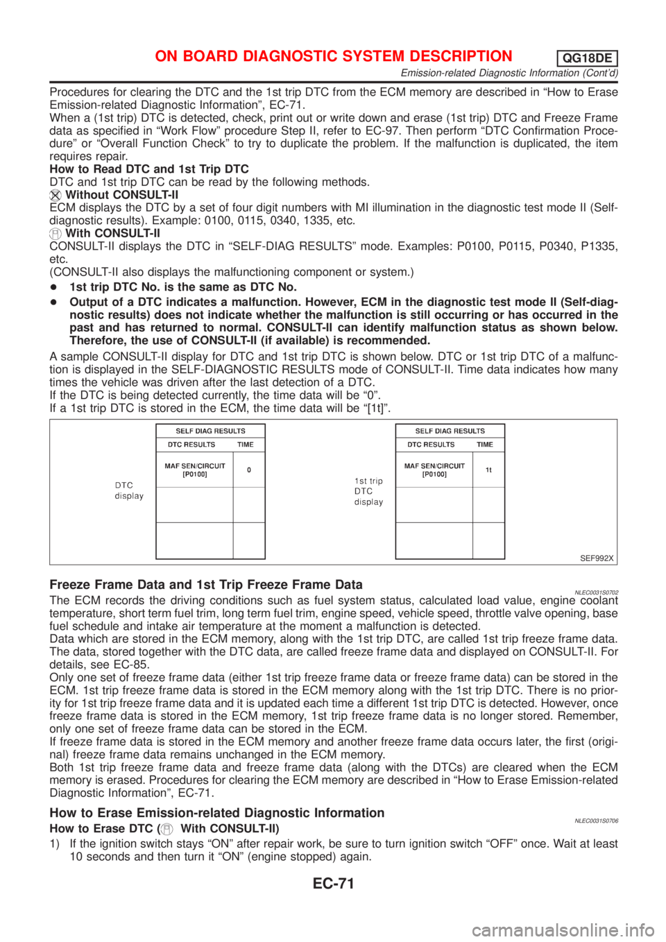
A sample CONSULT-II display for DTC and 1st trip DTC is shown below. DTC or 1st trip DTC of a malfunc-
tion is displayed in the SELF-DIAGNOSTIC RESULTS mode of CONSULT-II. Time data indicates how many
times the vehicle was driven after the last detection of a DTC.
If the DTC is being detected currently, the time data will be ª0º.
If a 1st trip DTC is stored in the ECM, the time data will be ª[1t]º.
SEF992X
Freeze Frame Data and 1st Trip Freeze Frame DataNLEC0031S0702The ECM records the driving conditions such as fuel system status, calculated load value, engine coolant
temperature, short term fuel trim, long term fuel trim, engine speed, vehicle speed, throttle valve opening, base
fuel schedule and intake air temperature at the moment a malfunction is detected.
Data which are stored in the ECM memory, along with the 1st trip DTC, are called 1st trip freeze frame data.
The data, stored together with the DTC data, are called freeze frame data and displayed on CONSULT-II. For
details, see EC-85.
Only one set of freeze frame data (either 1st trip freeze frame data or freeze frame data) can be stored in the
ECM. 1st trip freeze frame data is stored in the ECM memory along with the 1st trip DTC. There is no prior-
ity for 1st trip freeze frame data and it is updated each time a different 1st trip DTC is detected. However, once
freeze frame data is stored in the ECM memory, 1st trip freeze frame data is no longer stored. Remember,
only one set of freeze frame data can be stored in the ECM.
If freeze frame data is stored in the ECM memory and another freeze frame data occurs later, the first (origi-
nal) freeze frame data remains unchanged in the ECM memory.
Both 1st trip freeze frame data and freeze frame data (along with the DTCs) are cleared when the ECM
memory is erased. Procedures for clearing the ECM memory are described in ªHow to Erase Emission-related
Diagnostic Informationº, EC-71.
How to Erase Emission-related Diagnostic InformationNLEC0031S0706How to Erase DTC (With CONSULT-II)
1) If the ignition switch stays ªONº after repair work, be sure to turn ignition switch ªOFFº once. Wait at least
10 seconds and then turn it ªONº (engine stopped) again.
ON BOARD DIAGNOSTIC SYSTEM DESCRIPTIONQG18DE
Emission-related Diagnostic Information (Cont'd)
EC-71
Page 515 of 3051
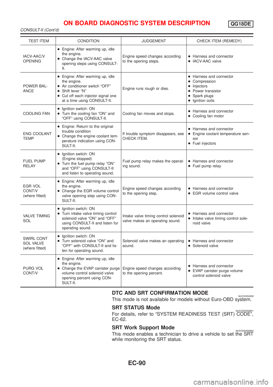
TEST ITEM CONDITION JUDGEMENT CHECK ITEM (REMEDY)
IACV-AAC/V
OPENING+Engine: After warming up, idle
the engine.
+Change the IACV-AAC valve
opening steps using CONSULT-
II.Engine speed changes according
to the opening steps.+Harness and connector
+IACV-AAC valve
POWER BAL-
ANCE+Engine: After warming up, idle
the engine.
+Air conditioner switch ªOFFº
+Shift lever ªNº
+Cut off each injector signal one
at a time using CONSULT-II.Engine runs rough or dies.+Harness and connector
+Compression
+Injectors
+Power transistor
+Spark plugs
+Ignition coils
COOLING FAN+Ignition switch: ON
+Turn the cooling fan ªONº and
ªOFFº using CONSULT-II.Cooling fan moves and stops.+Harness and connector
+Cooling fan motor
ENG COOLANT
TEMP+Engine: Return to the original
trouble condition
+Change the engine coolant tem-
perature indication using CON-
SULT-II.If trouble symptom disappears, see
CHECK ITEM.+Harness and connector
+Engine coolant temperature sen-
sor
+Fuel injectors
FUEL PUMP
RELAY+Ignition switch: ON
(Engine stopped)
+Turn the fuel pump relay ªONº
and ªOFFº using CONSULT-II
and listen to operating sound.Fuel pump relay makes the operat-
ing sound.+Harness and connector
+Fuel pump relay
EGR VOL
CONT/V
(where fitted)+Engine: After warming up, idle
the engine.
+Change the EGR volume control
valve opening step using CON-
SULT-II.Engine speed changes according
to the opening step.+Harness and connector
+EGR volume control valve
VALVE TIMING
SOL+Ignition switch: ON
+Turn intake valve timing control
solenoid valve ªONº and ªOFFº
using CONSULT-II and listen for
operating sound.Intake valve timing control solenoid
valve makes an operating sound.+Harness and connector
+Intake valve timing control sole-
noid valve
SWIRL CONT
S O L VA LV E
(where fitted)+Ignition switch: ON
+Turn solenoid valve ªONº and
ªOFFº with CONSULT-II and lis-
ten for operating sound.Solenoid valve makes an operating
sound.+Harness and connector
+Solenoid valve
PURG VOL
CONT/V+Engine: After warming up, idle
the engine.
+Change the EVAP canister purge
volume control solenoid valve
opening percent using CON-
SULT-II.Engine speed changes according
to the opening percent.+Harness and connector
+EVAP canister purge volume
control solenoid valve
DTC AND SRT CONFIRMATION MODENLEC0034S08This mode is not available for models without Euro-OBD system.
SRT STATUS ModeNLEC0034S0801For details, refer to ªSYSTEM READINESS TEST (SRT) CODEº,
EC-62.
SRT Work Support ModeNLEC0034S0803This mode enables a technician to drive a vehicle to set the SRT
while monitoring the SRT status.
ON BOARD DIAGNOSTIC SYSTEM DESCRIPTIONQG18DE
CONSULT-II (Cont'd)
EC-90
Page 516 of 3051
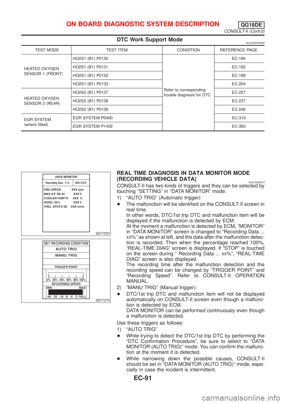
DTC Work Support ModeNLEC0034S0802
TEST MODE TEST ITEM CONDITION REFERENCE PAGE
HEATED OXYGEN
SENSOR 1 (FRONT)HO2S1 (B1) P0130
Refer to corresponding
trouble diagnosis for DTC.EC-184
HO2S1 (B1) P0131 EC-192
HO2S1 (B1) P0132 EC-198
HO2S1 (B1) P0133 EC-204
HEATED OXYGEN
SENSOR 2 (REAR)HO2S2 (B1) P0137 EC-227
HO2S2 (B1) P0138 EC-237
HO2S2 (B1) P0139 EC-246
EGR SYSTEM
(where fitted)EGR SYSTEM P0400 EC-310
EGR SYSTEM P1402 EC-393
SEF705Y
SEF707X
REAL TIME DIAGNOSIS IN DATA MONITOR MODE
(RECORDING VEHICLE DATA)
NLEC0034S10CONSULT-II has two kinds of triggers and they can be selected by
touching ªSETTINGº in ªDATA MONITORº mode.
1) ªAUTO TRIGº (Automatic trigger):
+The malfunction will be identified on the CONSULT-II screen in
real time.
In other words, DTC/1st trip DTC and malfunction item will be
displayed if the malfunction is detected by ECM.
At the moment a malfunction is detected by ECM, ªMONITORº
in ªDATA MONITORº screen is changed to ªRecording Data ...
xx%º as shown at left, and the data after the malfunction detec-
tion is recorded. Then when the percentage reached 100%,
ªREAL-TIME DIAGº screen is displayed. If ªSTOPº is touched
on the screen during ª Recording Data ... xx%º, ªREAL-TIME
DIAGº screen is also displayed.
The recording time after the malfunction detection and the
recording speed can be changed by ªTRIGGER POINTº and
ªRecording Speedº. Refer to CONSULT-II OPERATION
MANUAL.
2) ªMANU TRIGº (Manual trigger):
+DTC/1st trip DTC and malfunction item will not be displayed
automatically on CONSULT-II screen even though a malfunc-
tion is detected by ECM.
DATA MONITOR can be performed continuously even though
a malfunction is detected.
Use these triggers as follows:
1) ªAUTO TRIGº
+While trying to detect the DTC/1st trip DTC by performing the
ªDTC Confirmation Procedureº, be sure to select to ªDATA
MONITOR (AUTO TRIG)º mode. You can confirm the malfunc-
tion at the moment it is detected.
+While narrowing down the possible causes, CONSULT-II
should be set in ªDATA MONITOR (AUTO TRIG)º mode, espe-
cially in case the incident is intermittent.
ON BOARD DIAGNOSTIC SYSTEM DESCRIPTIONQG18DE
CONSULT-II (Cont'd)
EC-91
Page 553 of 3051

CONSULT-II Reference Value in Data Monitor
Mode
NLEC0042Remarks:
+Specification data are reference values.
+Specification data are output/input values which are detected or supplied by the ECM at the connector.
* Specification data may not be directly related to their components signals/values/operations.
(i.e., Adjust ignition timing with a timing light before monitoring IGN TIMING. Specification data might be displayed even when igni-
tion timing is not adjusted to specification. This IGN TIMING monitors the data calculated by the ECM according to the input signals
from the crankshaft position sensor and other ignition timing related sensors.)
+If the real-time diagnosis results are NG, and the on board diagnostic system results are OK, when diagnosing the mass air flow sensor,
first check to see if the fuel pump control circuit is normal.
MONITOR ITEM CONDITION SPECIFICATION
ENG SPEED+Tachometer: Connect
+Run engine and compare tachometer indication with the CONSULT-II
value.Almost the same speed as the
CONSULT-II value.
MAS A/F SE-B1+Engine: After warming up
+Air conditioner switch: OFF
+Shift lever: ªNº
+No-loadIdle 1.0 - 1.7V
2,500 rpm 1.5 - 2.1V
B/FUEL SCHDL+Engine: After warming up
+Air conditioner switch: OFF
+Shift lever: ªNº
+No-loadIdle 1.5 - 3.0 msec
2,000 rpm 1.2 - 3.0 msec
A/F ALPHA-B1+Engine: After warming upMaintaining engine speed at 2,000
rpm75 - 125%
COOLAN TEMP/S+Engine: After warming up More than 70ÉC (158ÉF)
HO2S1 (B1)
+Engine: After warming upMaintaining engine speed at 2,000
rpm0 - 0.3V¨0.6 - 1.0V
HO2S1 MNTR (B1)LEAN¨RICH
Changes more than 5 times
during 10 seconds.
HO2S2 (B1)
+Engine: After warming upRevving engine from idle to 3,000
rpm quickly0 - 0.3V¨0.6 - 1.0V
HO2S2 MNTR (B1)LEAN¨RICH
VHCL SPEED SE+Turn drive wheels and compare speedometer indication with the CON-
SULT-II valueAlmost the same speed as the
CONSULT-II value
BATTERY VOLT+Ignition switch: ON (Engine stopped) 11 - 14V
THRTL POS SEN+Engine: Idle Throttle valve fully closed 0.15 - 0.85V
+Ignition switch: ON
(Engine stopped)Throttle valve fully opened 3.5 - 4.7V
EGR TEMP SEN
(where fitted)+Engine: After warming up Less than 4.5V
START SIGNAL+Ignition switch: ON®START®ON OFF®ON®OFF
CLSD THL POS
CLSD THL/P SW
(where fitted)+Engine: Idle
Throttle valve: Idle position ON
+Ignition switch: ON
(Engine stopped)Throttle valve: Slightly open OFF
AIR COND SIG+Engine: After warming up, idle
the engineA/C switch ªOFFº OFF
A/C switch ªONº
(Compressor operates)ON
P/N POSI SW+Ignition switch: ONShift lever ªPº or ªNº ON
Except above OFF
TROUBLE DIAGNOSIS Ð GENERAL DESCRIPTIONQG18DE
CONSULT-II Reference Value in Data Monitor Mode
EC-128
Page 609 of 3051
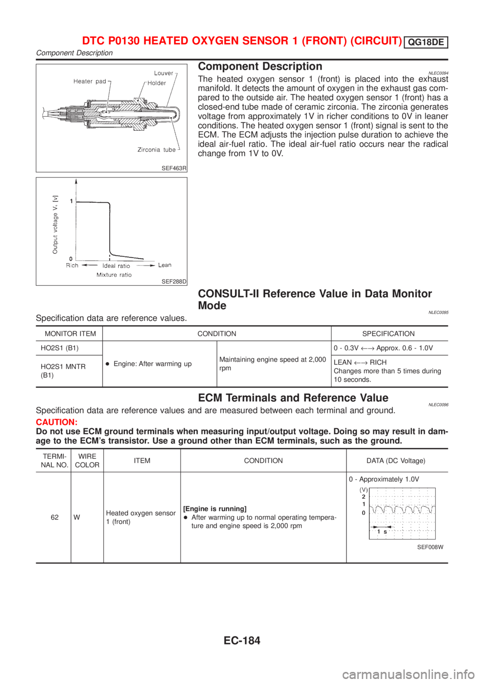
SEF463R
SEF288D
Component DescriptionNLEC0094The heated oxygen sensor 1 (front) is placed into the exhaust
manifold. It detects the amount of oxygen in the exhaust gas com-
pared to the outside air. The heated oxygen sensor 1 (front) has a
closed-end tube made of ceramic zirconia. The zirconia generates
voltage from approximately 1V in richer conditions to 0V in leaner
conditions. The heated oxygen sensor 1 (front) signal is sent to the
ECM. The ECM adjusts the injection pulse duration to achieve the
ideal air-fuel ratio. The ideal air-fuel ratio occurs near the radical
change from 1V to 0V.
CONSULT-II Reference Value in Data Monitor
Mode
NLEC0095Specification data are reference values.
MONITOR ITEM CONDITION SPECIFICATION
HO2S1 (B1)
+Engine: After warming upMaintaining engine speed at 2,000
rpm0 - 0.3V¨Approx. 0.6 - 1.0V
HO2S1 MNTR
(B1)LEAN¨RICH
Changes more than 5 times during
10 seconds.
ECM Terminals and Reference ValueNLEC0096Specification data are reference values and are measured between each terminal and ground.
CAUTION:
Do not use ECM ground terminals when measuring input/output voltage. Doing so may result in dam-
age to the ECM's transistor. Use a ground other than ECM terminals, such as the ground.
TERMI-
NAL NO.WIRE
COLORITEM CONDITION DATA (DC Voltage)
62 WHeated oxygen sensor
1 (front)[Engine is running]
+After warming up to normal operating tempera-
ture and engine speed is 2,000 rpm0 - Approximately 1.0V
SEF008W
DTC P0130 HEATED OXYGEN SENSOR 1 (FRONT) (CIRCUIT)QG18DE
Component Description
EC-184
Page 610 of 3051
SEF237U
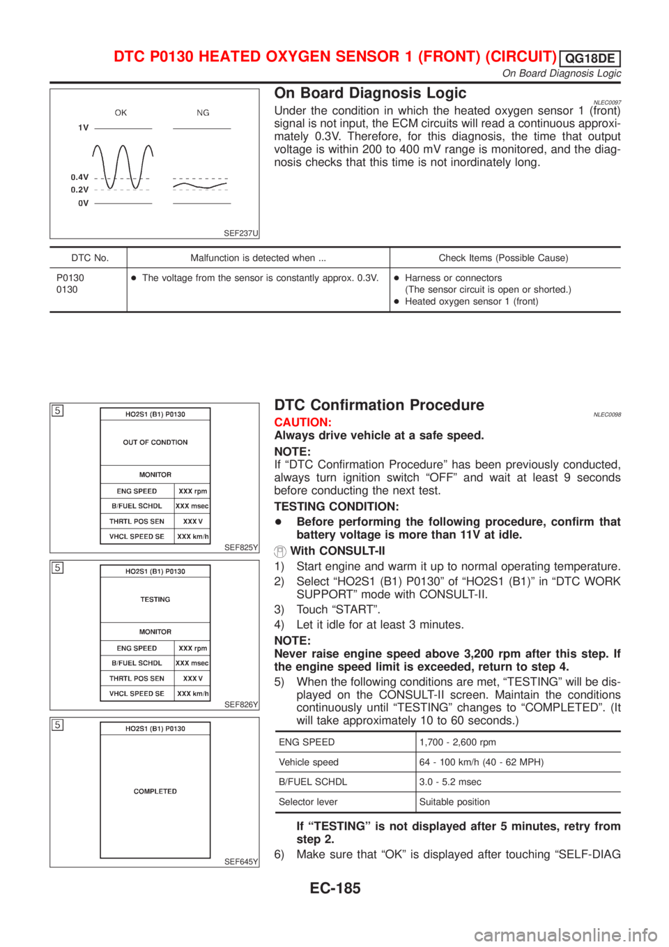
On Board Diagnosis LogicNLEC0097Under the condition in which the heated oxygen sensor 1 (front)
signal is not input, the ECM circuits will read a continuous approxi-
mately 0.3V. Therefore, for this diagnosis, the time that output
voltage is within 200 to 400 mV range is monitored, and the diag-
nosis checks that this time is not inordinately long.
DTC No. Malfunction is detected when ... Check Items (Possible Cause)
P0130
0130+The voltage from the sensor is constantly approx. 0.3V.+Harness or connectors
(The sensor circuit is open or shorted.)
+Heated oxygen sensor 1 (front)
SEF825Y
SEF826Y
SEF645Y
DTC Confirmation ProcedureNLEC0098CAUTION:
Always drive vehicle at a safe speed.
NOTE:
If ªDTC Confirmation Procedureº has been previously conducted,
always turn ignition switch ªOFFº and wait at least 9 seconds
before conducting the next test.
TESTING CONDITION:
+Before performing the following procedure, confirm that
battery voltage is more than 11V at idle.
With CONSULT-II
1) Start engine and warm it up to normal operating temperature.
2) Select ªHO2S1 (B1) P0130º of ªHO2S1 (B1)º in ªDTC WORK
SUPPORTº mode with CONSULT-II.
3) Touch ªSTARTº.
4) Let it idle for at least 3 minutes.
NOTE:
Never raise engine speed above 3,200 rpm after this step. If
the engine speed limit is exceeded, return to step 4.
5) When the following conditions are met, ªTESTINGº will be dis-
played on the CONSULT-II screen. Maintain the conditions
continuously until ªTESTINGº changes to ªCOMPLETEDº. (It
will take approximately 10 to 60 seconds.)
ENG SPEED 1,700 - 2,600 rpm
Vehicle speed 64 - 100 km/h (40 - 62 MPH)
B/FUEL SCHDL 3.0 - 5.2 msec
Selector lever Suitable position
If ªTESTINGº is not displayed after 5 minutes, retry from
step 2.
6) Make sure that ªOKº is displayed after touching ªSELF-DIAG
DTC P0130 HEATED OXYGEN SENSOR 1 (FRONT) (CIRCUIT)QG18DE
On Board Diagnosis Logic
EC-185
Page 615 of 3051
SEF646Y
SEF647Y
Component InspectionNLEC0102HEATED OXYGEN SENSOR 1 (FRONT)NLEC0102S01With CONSULT-II
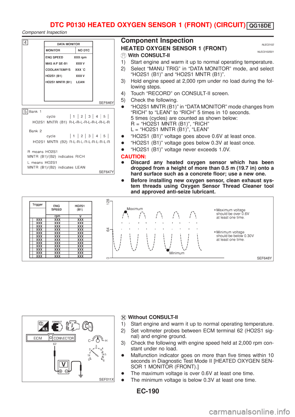
1) Start engine and warm it up to normal operating temperature.
2) Select ªMANU TRIGº in ªDATA MONITORº mode, and select
ªHO2S1 (B1)º and ªHO2S1 MNTR (B1)º.
3) Hold engine speed at 2,000 rpm under no load during the fol-
lowing steps.
4) Touch ªRECORDº on CONSULT-II screen.
5) Check the following.
+ªHO2S1 MNTR (B1)º in ªDATA MONITORº mode changes from
ªRICHº to ªLEANº to ªRICHº 5 times in 10 seconds.
5 times (cycles) are counted as shown below:
R = ªHO2S1 MNTR (B1)º, ªRICHº
L = ªHO2S1 MNTR (B1)º, ªLEANº
+ªHO2S1 (B1)º voltage goes above 0.6V at least once.
+ªHO2S1 (B1)º voltage goes below 0.3V at least once.
+ªHO2S1 (B1)º voltage never exceeds 1.0V.
CAUTION:
+Discard any heated oxygen sensor which has been
dropped from a height of more than 0.5 m (19.7 in) onto a
hard surface such as a concrete floor; use a new one.
+Before installing new oxygen sensor, clean exhaust sys-
tem threads using Oxygen Sensor Thread Cleaner tool
and approved anti-seize lubricant.
SEF648Y
SEF011X
Without CONSULT-II
1) Start engine and warm it up to normal operating temperature.
2) Set voltmeter probes between ECM terminal 62 (HO2S1 sig-
nal) and engine ground.
3) Check the following with engine speed held at 2,000 rpm con-
stant under no load.
+Malfunction indicator goes on more than five times within 10
seconds in Diagnostic Test Mode II [HEATED OXYGEN SEN-
SOR 1 MONITOR (FRONT).]
+The maximum voltage is over 0.6V at least one time.
+The minimum voltage is below 0.3V at least one time.
DTC P0130 HEATED OXYGEN SENSOR 1 (FRONT) (CIRCUIT)QG18DE
Component Inspection
EC-190
Page 617 of 3051
SEF463R
SEF288D
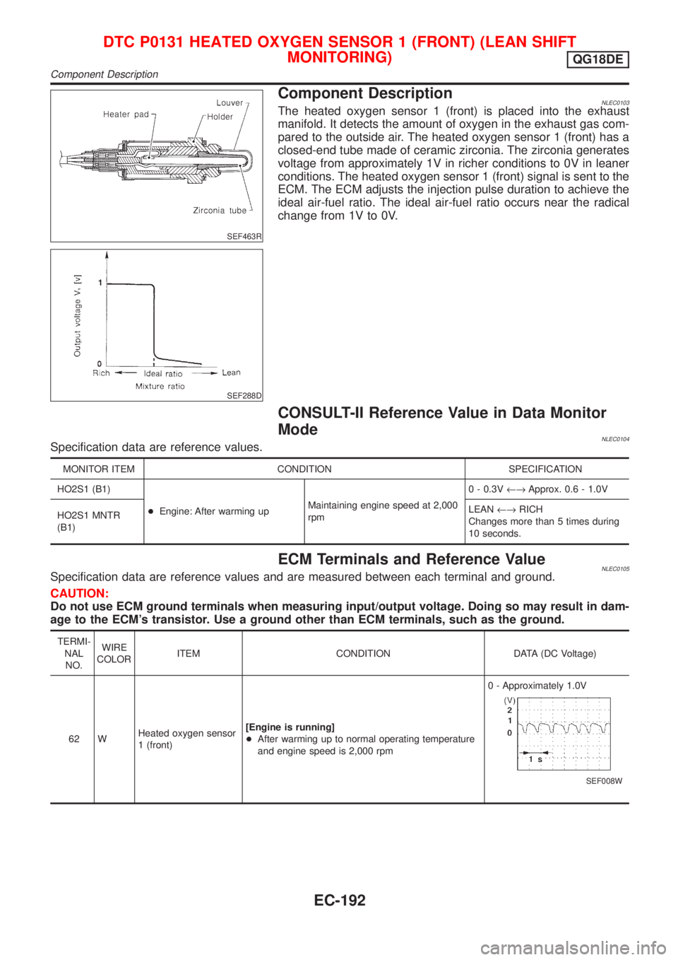
Component DescriptionNLEC0103The heated oxygen sensor 1 (front) is placed into the exhaust
manifold. It detects the amount of oxygen in the exhaust gas com-
pared to the outside air. The heated oxygen sensor 1 (front) has a
closed-end tube made of ceramic zirconia. The zirconia generates
voltage from approximately 1V in richer conditions to 0V in leaner
conditions. The heated oxygen sensor 1 (front) signal is sent to the
ECM. The ECM adjusts the injection pulse duration to achieve the
ideal air-fuel ratio. The ideal air-fuel ratio occurs near the radical
change from 1V to 0V.
CONSULT-II Reference Value in Data Monitor
Mode
NLEC0104Specification data are reference values.
MONITOR ITEM CONDITION SPECIFICATION
HO2S1 (B1)
+Engine: After warming upMaintaining engine speed at 2,000
rpm0 - 0.3V¨Approx. 0.6 - 1.0V
HO2S1 MNTR
(B1)LEAN¨RICH
Changes more than 5 times during
10 seconds.
ECM Terminals and Reference ValueNLEC0105Specification data are reference values and are measured between each terminal and ground.
CAUTION:
Do not use ECM ground terminals when measuring input/output voltage. Doing so may result in dam-
age to the ECM's transistor. Use a ground other than ECM terminals, such as the ground.
TERMI-
NAL
NO.WIRE
COLORITEM CONDITION DATA (DC Voltage)
62 WHeated oxygen sensor
1 (front)[Engine is running]
+After warming up to normal operating temperature
and engine speed is 2,000 rpm0 - Approximately 1.0V
SEF008W
DTC P0131 HEATED OXYGEN SENSOR 1 (FRONT) (LEAN SHIFT
MONITORING)
QG18DE
Component Description
EC-192