Page 1623 of 2898
Aiming AdjustmentNJEL0016For details, refer to the regulations in your own country.
Before performing aiming adjustment, check the following.
1) Keep all tires inflated to correct pressures.
2) Place vehicle on flat surface.
3) See that there is no-load in vehicle (coolant, engine oil filled up
to correct level and full fuel tank) other than the driver (or
equivalent weight placed in driver's position).
SEL984W
CAUTION:
Be sure aiming switch is set to ª0º when performing aiming
adjustment on vehicles equipped with headlamp aiming con-
trol.
HEADLAMP
Aiming Adjustment
EL-65
Page 1625 of 2898

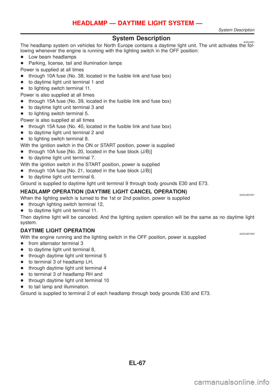
System DescriptionNJEL0351The headlamp system on vehicles for North Europe contains a daytime light unit. The unit activates the fol-
lowing whenever the engine is running with the lighting switch in the OFF position:
+Low beam headlamps
+Parking, license, tail and illumination lamps
Power is supplied at all times
+through 10A fuse (No. 38, located in the fusible link and fuse box)
+to daytime light unit terminal 1 and
+to lighting switch terminal 11.
Power is also supplied at all times
+through 15A fuse (No. 39, located in the fusible link and fuse box)
+to daytime light unit terminal 3 and
+to lighting switch terminal 5.
Power is also supplied at all times
+through 15A fuse (No. 40, located in the fusible link and fuse box)
+to daytime light unit terminal 2 and
+to lighting switch terminal 8.
With the ignition switch in the ON or START position, power is supplied
+through 10A fuse [No. 20, located in the fuse block (J/B)]
+to daytime light unit terminal 7.
With the ignition switch in the START position, power is supplied
+through 10A fuse [No. 21, located in the fuse block (J/B)]
+to daytime light unit terminal 6.
Ground is supplied to daytime light unit terminal 9 through body grounds E30 and E73.
HEADLAMP OPERATION (DAYTIME LIGHT CANCEL OPERATION)NJEL0351S01When the lighting switch is turned to the 1st or 2nd position, power is supplied
+through lighting switch terminal 12,
+to daytime light unit terminal 11.
Then daytime light will be canceled. And the lighting system operation will be the same as no daytime light
system.
DAYTIME LIGHT OPERATIONNJEL0351S02With the engine running and the lighting switch in the OFF position, power is supplied
+from alternator terminal 3
+to daytime light unit terminal 8,
+through daytime light unit terminal 5
+to terminal 3 of headlamp LH,
+through daytime light unit terminal 4
+to terminal 3 of headlamp RH and
+through daytime light unit terminal 10
+to tail lamp and illumination.
Ground is supplied to terminal 2 of each headlamp through body grounds E30 and E73.
HEADLAMP Ð DAYTIME LIGHT SYSTEM Ð
System Description
EL-67
Page 1634 of 2898
Trouble DiagnosesNJEL0354DAYTIME LIGHT UNIT INSPECTION TABLENJEL0354S01
Terminal No. ConnectionsINPUT (I)/ OUT-
PUT (O)Operated conditionVoltage (V)
(Approximate val-
ues)
1Power source for illumina-
tion & tail lampÐÐ12
2Power source for headlamp
LHÐÐ12
3Power source for headlamp
RHÐÐ12
4 Headlamp RH OON (daytime light operating*) 12
OFF 0
5 Headlamp LH OON (daytime light operating*) 12
OFF 0
6 Start signal I Ignition switchSTART 12
ON, ACC or OFF 0
7 Power source Ð Ignition switchON or START 12
ACC or OFF 0
8 Alternator ªLº terminal I EngineRunning 12
Stopped 0
9 Ground Ð Ð Ð
10 Illumination & tail lamp OON (daytime light operating*) 12
OFF 0
11 Lighting switch I1ST´2ND position 12
OFF 0
*: Daytime light operating: Lighting switch in ªOFFº position with engine running.
Bulb ReplacementNJEL0355Refer to ªHEADLAMPº (EL-64).
HEADLAMP Ð DAYTIME LIGHT SYSTEM Ð
Trouble Diagnoses
EL-76
Page 1650 of 2898

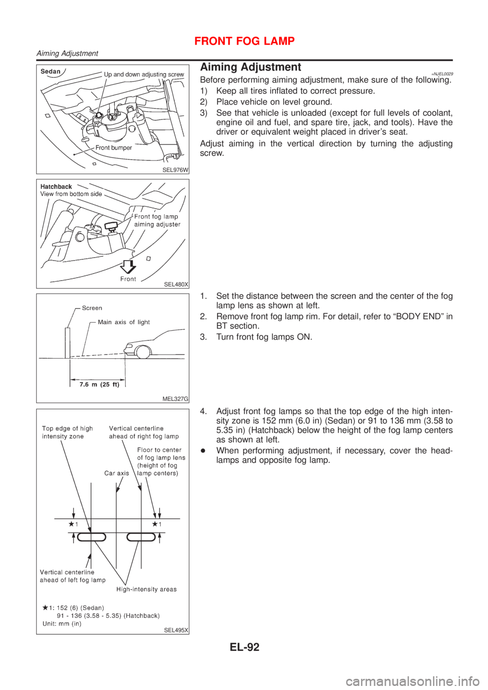
SEL976W
SEL480X
Aiming Adjustment=NJEL0029Before performing aiming adjustment, make sure of the following.
1) Keep all tires inflated to correct pressure.
2) Place vehicle on level ground.
3) See that vehicle is unloaded (except for full levels of coolant,
engine oil and fuel, and spare tire, jack, and tools). Have the
driver or equivalent weight placed in driver's seat.
Adjust aiming in the vertical direction by turning the adjusting
screw.
MEL327G
1. Set the distance between the screen and the center of the fog
lamp lens as shown at left.
2. Remove front fog lamp rim. For detail, refer to ªBODY ENDº in
BT section.
3. Turn front fog lamps ON.
SEL495X
4. Adjust front fog lamps so that the top edge of the high inten-
sity zone is 152 mm (6.0 in) (Sedan) or 91 to 136 mm (3.58 to
5.35 in) (Hatchback) below the height of the fog lamp centers
as shown at left.
+When performing adjustment, if necessary, cover the head-
lamps and opposite fog lamp.
FRONT FOG LAMP
Aiming Adjustment
EL-92
Page 1703 of 2898
![NISSAN ALMERA 2001 Service Manual POWER SUPPLY AND GROUND CIRCUITNJEL0042S08Power is supplied at all times
+through 10A fuse [No. 12, located in the fuse block (J/B)]
+to combination meter terminal 18 (with tachometer) or 21 (without NISSAN ALMERA 2001 Service Manual POWER SUPPLY AND GROUND CIRCUITNJEL0042S08Power is supplied at all times
+through 10A fuse [No. 12, located in the fuse block (J/B)]
+to combination meter terminal 18 (with tachometer) or 21 (without](/manual-img/5/57348/w960_57348-1702.png)
POWER SUPPLY AND GROUND CIRCUITNJEL0042S08Power is supplied at all times
+through 10A fuse [No. 12, located in the fuse block (J/B)]
+to combination meter terminal 18 (with tachometer) or 21 (without tachometer).
With the ignition switch in the ON or START position, power is supplied
+through 10A fuse [No. 30, located in the fuse block (J/B)]
+to combination meter terminal 17 (with tachometer) or 22 (without tachometer).
Ground is supplied
+through body grounds M28 and M67
+to combination meter terminal 24 (with tachometer) or 23 (without tachometer).
WATER TEMPERATURE GAUGENJEL0042S01The water temperature gauge indicates the engine coolant temperature. The reading on the gauge is based
on the resistance of the thermal transmitter.
As the temperature of the coolant increases, the resistance of the thermal transmitter decreases. A variable
ground is supplied to terminal 19 (with tachometer) or 34 (without tachometer) of the combination meter for
the water temperature gauge. The needle on the gauge moves from ªCº to ªHº.
TACHOMETERNJEL0042S02The tachometer indicates engine speed in revolutions per minute (rpm).
The tachometer is regulated by a signal
+from terminal 32 (Gasoline engine models) or 439 (Diesel engine models) of the ECM
+to combination meter terminal 21 for the tachometer.
FUEL GAUGENJEL0042S03The fuel gauge indicates the approximate fuel level in the fuel tank.
The fuel gauge is regulated by a variable ground signal supplied
+from body grounds B9, B21 and B308
+through terminal 1 (Gasoline engine models) or 3 (Diesel engine models) of the fuel level sensor unit and
+through terminal 4 (Gasoline engine models) or 1 (Diesel engine models) of the fuel level sensor unit
+to combination meter terminal 20 (with tachometer) or 35 (without tachometer) for the fuel gauge.
SPEEDOMETERNJEL0042S04The combination meter provides a voltage signal to the vehicle speed sensor for the speedometer.
The voltage is supplied
+from combination meter terminal 23 (with tachometer) or 37 (without tachometer) for the speedometer
+to terminal 1 of the vehicle speed sensor.
The speedometer converts the voltage into the vehicle speed displayed.
METERS AND GAUGES
System Description/Sedan (Cont'd)
EL-145
Page 1713 of 2898

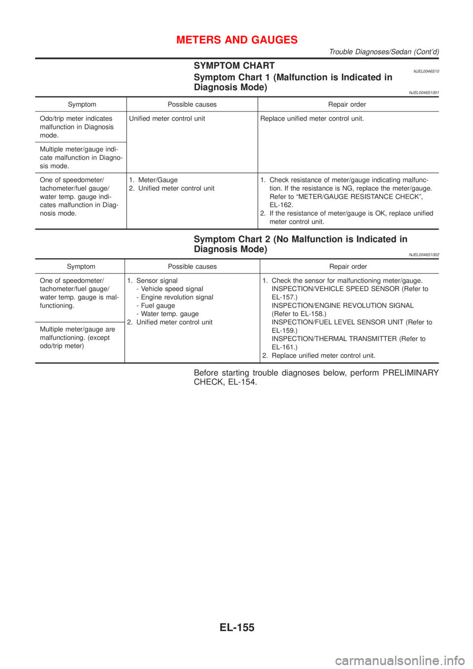
SYMPTOM CHARTNJEL0046S10Symptom Chart 1 (Malfunction is Indicated in
Diagnosis Mode)
NJEL0046S1001
Symptom Possible causes Repair order
Odo/trip meter indicates
malfunction in Diagnosis
mode.Unified meter control unit Replace unified meter control unit.
Multiple meter/gauge indi-
cate malfunction in Diagno-
sis mode.
One of speedometer/
tachometer/fuel gauge/
water temp. gauge indi-
cates malfunction in Diag-
nosis mode.1. Meter/Gauge
2. Unified meter control unit1. Check resistance of meter/gauge indicating malfunc-
tion. If the resistance is NG, replace the meter/gauge.
Refer to ªMETER/GAUGE RESISTANCE CHECKº,
EL-162.
2. If the resistance of meter/gauge is OK, replace unified
meter control unit.
Symptom Chart 2 (No Malfunction is Indicated in
Diagnosis Mode)
NJEL0046S1002
Symptom Possible causes Repair order
One of speedometer/
tachometer/fuel gauge/
water temp. gauge is mal-
functioning.1. Sensor signal
- Vehicle speed signal
- Engine revolution signal
- Fuel gauge
- Water temp. gauge
2. Unified meter control unit1. Check the sensor for malfunctioning meter/gauge.
INSPECTION/VEHICLE SPEED SENSOR (Refer to
EL-157.)
INSPECTION/ENGINE REVOLUTION SIGNAL
(Refer to EL-158.)
INSPECTION/FUEL LEVEL SENSOR UNIT (Refer to
EL-159.)
INSPECTION/THERMAL TRANSMITTER (Refer to
EL-161.)
2. Replace unified meter control unit. Multiple meter/gauge are
malfunctioning. (except
odo/trip meter)
Before starting trouble diagnoses below, perform PRELIMINARY
CHECK, EL-154.
METERS AND GAUGES
Trouble Diagnoses/Sedan (Cont'd)
EL-155
Page 1716 of 2898
INSPECTION/ENGINE REVOLUTION SIGNAL=NJEL0046S02
1 CHECK ECM OUTPUT
1. Start engine.
2. Check voltage between combination meter terminals 21 and ground at idle and 2,000 rpm.
SEL658X
OK or NG
OK©Engine revolution signal is OK.
NG©Harness for open or short between ECM and combination meter
METERS AND GAUGES
Trouble Diagnoses/Sedan (Cont'd)
EL-158
Page 1717 of 2898
INSPECTION/FUEL LEVEL SENSOR UNIT=NJEL0046S08
1 CHECK GROUND CIRCUIT FOR FUEL LEVEL SENSOR UNIT
Check harness continuity between fuel level sensor unit connector terminal 1 (Gasoline engine models) or 3 (Diesel
engine models) and ground.
SEL963W
OK or NG
OK©GO TO 2.
NG©Repair harness or connector.
2 CHECK FUEL LEVEL SENSOR UNIT
Refer to ªFUEL LEVEL SENSOR UNIT CHECKº (EL-162).
OK or NG
OK©GO TO 3.
NG©Replace fuel level sensor unit.
METERS AND GAUGES
Trouble Diagnoses/Sedan (Cont'd)
EL-159