Page 119 of 2898
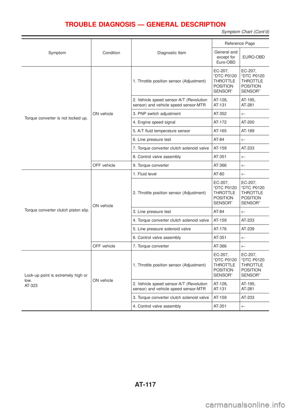
Symptom Condition Diagnostic ItemReference Page
General and
except for
Euro-OBDEURO-OBD
Torque converter is not locked up.ON vehicle1. Throttle position sensor (Adjustment)EC-207,
ªDTC P0120
THROTTLE
POSITION
SENSORºEC-207,
ªDTC P0120
THROTTLE
POSITION
SENSORº
2. Vehicle speed sensor´A/T (Revolution
sensor) and vehicle speed sensor´MTRAT-126,
AT-131AT-195,
AT-281
3. PNP switch adjustment AT-352¬
4. Engine speed signal AT-172 AT-200
5. A/T fluid temperature sensor AT-165 AT-189
6. Line pressure test AT-84¬
7. Torque converter clutch solenoid valve AT-159 AT-233
8. Control valve assembly AT-351¬
OFF vehicle 9. Torque converter AT-366¬
Torque converter clutch piston slip.ON vehicle1. Fluid level AT-80¬
2. Throttle position sensor (Adjustment)EC-207,
ªDTC P0120
THROTTLE
POSITION
SENSORºEC-207,
ªDTC P0120
THROTTLE
POSITION
SENSORº
3. Line pressure test AT-84¬
4. Torque converter clutch solenoid valve AT-159 AT-233
5. Line pressure solenoid valve AT-176 AT-239
6. Control valve assembly AT-351¬
OFF vehicle 7. Torque converter AT-366¬
Lock-up point is extremely high or
low.
AT-323ON vehicle1. Throttle position sensor (Adjustment)EC-207,
ªDTC P0120
THROTTLE
POSITION
SENSORºEC-207,
ªDTC P0120
THROTTLE
POSITION
SENSORº
2. Vehicle speed sensor´A/T (Revolution
sensor) and vehicle speed sensor´MTRAT-126,
AT-131AT-195,
AT-281
3. Torque converter clutch solenoid valve AT-159 AT-233
4. Control valve assembly AT-351¬
TROUBLE DIAGNOSIS Ð GENERAL DESCRIPTION
Symptom Chart (Cont'd)
AT-117
Page 120 of 2898
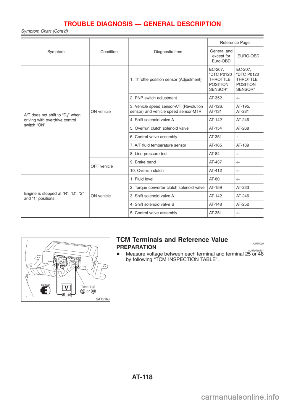
Symptom Condition Diagnostic ItemReference Page
General and
except for
Euro-OBDEURO-OBD
A/T does not shift to ªD
4º when
driving with overdrive control
switch ªONº.ON vehicle1. Throttle position sensor (Adjustment)EC-207,
ªDTC P0120
THROTTLE
POSITION
SENSORºEC-207,
ªDTC P0120
THROTTLE
POSITION
SENSORº
2. PNP switch adjustment AT-352¬
3. Vehicle speed sensor´A/T (Revolution
sensor) and vehicle speed sensor´MTRAT-126,
AT-131AT-195,
AT-281
4. Shift solenoid valve A AT-142 AT-246
5. Overrun clutch solenoid valve AT-154 AT-268
6. Control valve assembly AT-351¬
7. A/T fluid temperature sensor AT-165 AT-189
8. Line pressure test AT-84¬
OFF vehicle9. Brake band AT-437¬
10. Overrun clutch AT-412¬
Engine is stopped at ªRº, ªDº, ª2º
and ª1º positions.ON vehicle1. Fluid level AT-80¬
2. Torque converter clutch solenoid valve AT-159 AT-233
3. Shift solenoid valve A AT-142 AT-246
4. Shift solenoid valve B AT-148 AT-252
5. Control valve assembly AT-351¬
SAT216J
TCM Terminals and Reference ValueNJAT0030PREPARATIONNJAT0030S01+Measure voltage between each terminal and terminal 25 or 48
by following ªTCM INSPECTION TABLEº.
TROUBLE DIAGNOSIS Ð GENERAL DESCRIPTION
Symptom Chart (Cont'd)
AT-118
Page 121 of 2898
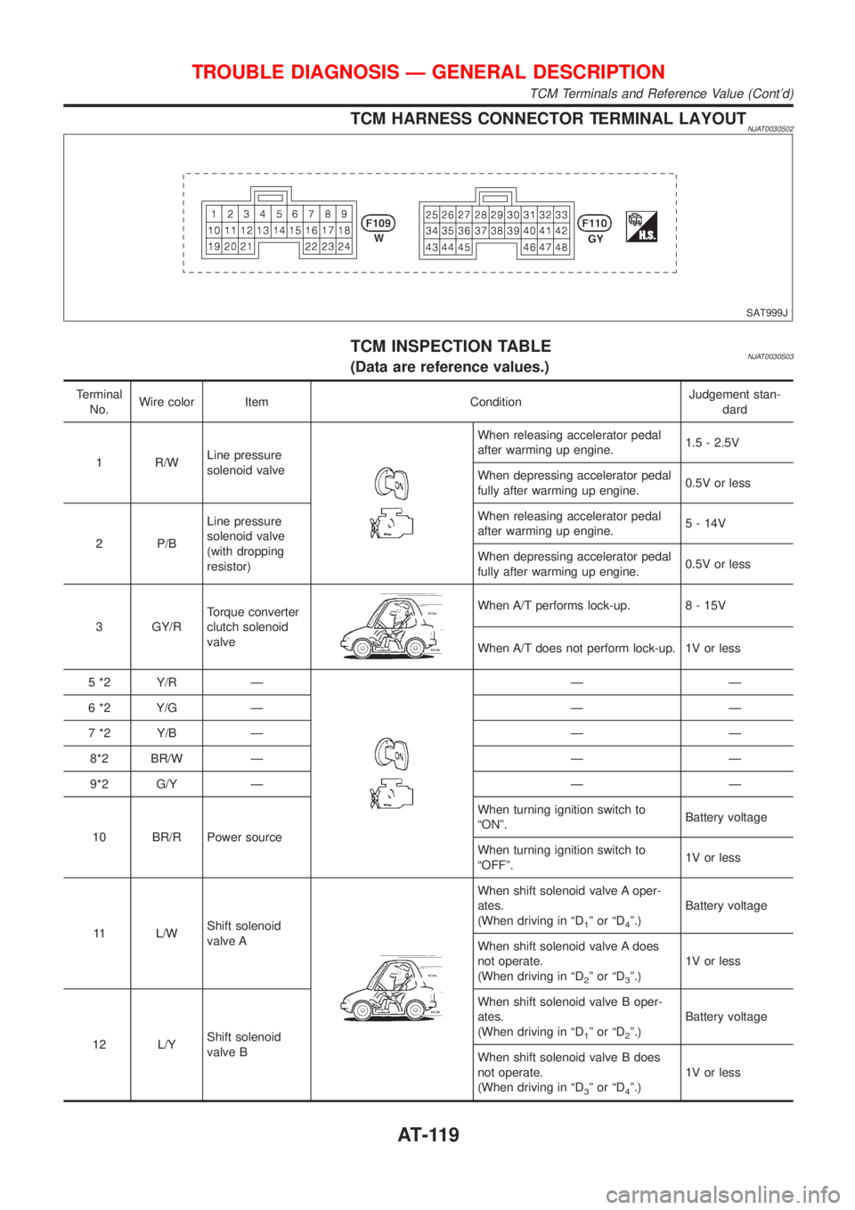
TCM HARNESS CONNECTOR TERMINAL LAYOUTNJAT0030S02
SAT999J
TCM INSPECTION TABLENJAT0030S03(Data are reference values.)
Terminal
No.Wire color Item ConditionJudgement stan-
dard
1 R/WLine pressure
solenoid valve
When releasing accelerator pedal
after warming up engine.1.5 - 2.5V
When depressing accelerator pedal
fully after warming up engine.0.5V or less
2 P/BLine pressure
solenoid valve
(with dropping
resistor)When releasing accelerator pedal
after warming up engine.5 - 14V
When depressing accelerator pedal
fully after warming up engine.0.5V or less
3 GY/RTorque converter
clutch solenoid
valve
When A/T performs lock-up. 8 - 15V
When A/T does not perform lock-up. 1V or less
5 *2 Y/R Ð
ÐÐ
6 *2 Y/G Ð Ð Ð
7 *2 Y/B Ð Ð Ð
8*2 BR/W Ð Ð Ð
9*2 G/Y Ð Ð Ð
10 BR/R Power sourceWhen turning ignition switch to
ªONº.Battery voltage
When turning ignition switch to
ªOFFº.1V or less
11 L/WShift solenoid
valve A
When shift solenoid valve A oper-
ates.
(When driving in ªD
1ºorªD4º.)Battery voltage
When shift solenoid valve A does
not operate.
(When driving in ªD
2ºorªD3º.)1V or less
12 L/YShift solenoid
valve BWhen shift solenoid valve B oper-
ates.
(When driving in ªD
1ºorªD2º.)Battery voltage
When shift solenoid valve B does
not operate.
(When driving in ªD
3ºorªD4º.)1V or less
TROUBLE DIAGNOSIS Ð GENERAL DESCRIPTION
TCM Terminals and Reference Value (Cont'd)
AT-119
Page 122 of 2898
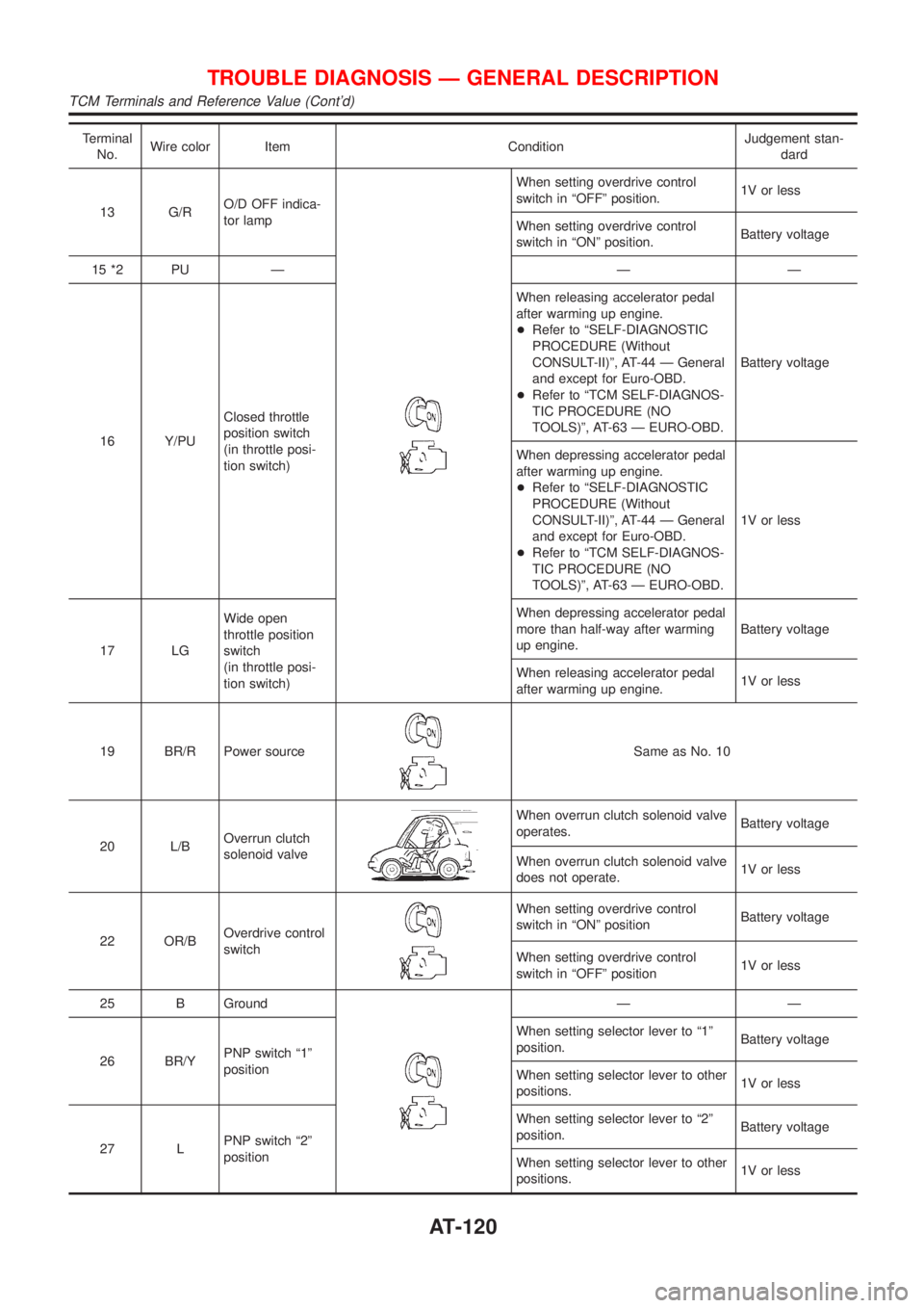
Terminal
No.Wire color Item ConditionJudgement stan-
dard
13 G/RO/D OFF indica-
tor lamp
When setting overdrive control
switch in ªOFFº position.1V or less
When setting overdrive control
switch in ªONº position.Battery voltage
15 *2 PU Ð Ð Ð
16 Y/PUClosed throttle
position switch
(in throttle posi-
tion switch)When releasing accelerator pedal
after warming up engine.
+Refer to ªSELF-DIAGNOSTIC
PROCEDURE (Without
CONSULT-II)º, AT-44 Ð General
and except for Euro-OBD.
+Refer to ªTCM SELF-DIAGNOS-
TIC PROCEDURE (NO
TOOLS)º, AT-63 Ð EURO-OBD.Battery voltage
When depressing accelerator pedal
after warming up engine.
+Refer to ªSELF-DIAGNOSTIC
PROCEDURE (Without
CONSULT-II)º, AT-44 Ð General
and except for Euro-OBD.
+Refer to ªTCM SELF-DIAGNOS-
TIC PROCEDURE (NO
TOOLS)º, AT-63 Ð EURO-OBD.1V or less
17 LGWide open
throttle position
switch
(in throttle posi-
tion switch)When depressing accelerator pedal
more than half-way after warming
up engine.Battery voltage
When releasing accelerator pedal
after warming up engine.1V or less
19 BR/R Power source
Same as No. 10
20 L/BOverrun clutch
solenoid valve
When overrun clutch solenoid valve
operates.Battery voltage
When overrun clutch solenoid valve
does not operate.1V or less
22 OR/BOverdrive control
switch
When setting overdrive control
switch in ªONº positionBattery voltage
When setting overdrive control
switch in ªOFFº position1V or less
25 B Ground
ÐÐ
26 BR/YPNP switch ª1º
positionWhen setting selector lever to ª1º
position.Battery voltage
When setting selector lever to other
positions.1V or less
27 LPNP switch ª2º
positionWhen setting selector lever to ª2º
position.Battery voltage
When setting selector lever to other
positions.1V or less
TROUBLE DIAGNOSIS Ð GENERAL DESCRIPTION
TCM Terminals and Reference Value (Cont'd)
AT-120
Page 123 of 2898
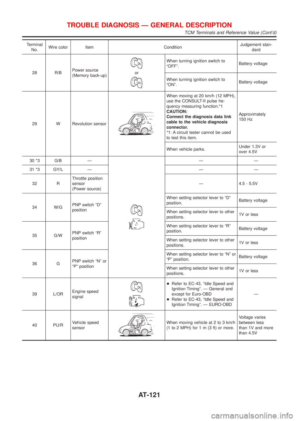
Terminal
No.Wire color Item ConditionJudgement stan-
dard
28 R/BPower source
(Memory back-up)
or
When turning ignition switch to
ªOFFº.Battery voltage
When turning ignition switch to
ªONº.Battery voltage
29 W Revolution sensor
When moving at 20 km/h (12 MPH),
use the CONSULT-II pulse fre-
quency measuring function.*1
CAUTION:
Connect the diagnosis data link
cable to the vehicle diagnosis
connector.
*1: A circuit tester cannot be used
to test this item.Approximately
150 Hz
When vehicle parks.Under 1.3V or
over 4.5V
30 *3 G/B Ð
ÐÐ
31 *3 GY/L Ð Ð Ð
32 RThrottle position
sensor
(Power source)Ð 4.5 - 5.5V
34 W/GPNP switch ªDº
positionWhen setting selector lever to ªDº
position.Battery voltage
When setting selector lever to other
positions.1V or less
35 G/WPNP switch ªRº
positionWhen setting selector lever to ªRº
position.Battery voltage
When setting selector lever to other
positions.1V or less
36 GPNP switch ªNº or
ªPº positionWhen setting selector lever to ªNº or
ªPº position.Battery voltage
When setting selector lever to other
positions.1V or less
39 L/OREngine speed
signal
+Refer to EC-43, ªIdle Speed and
Ignition Timingº. Ð General and
except for Euro-OBD
+Refer to EC-43, ªIdle Speed and
Ignition Timingº. Ð EURO-OBDÐ
40 PU/RVehicle speed
sensor
When moving vehicle at 2 to 3 km/h
(1 to 2 MPH) for1m(3ft)ormore.Voltage varies
between less
than 1V and more
than 4.5V
TROUBLE DIAGNOSIS Ð GENERAL DESCRIPTION
TCM Terminals and Reference Value (Cont'd)
AT-121
Page 124 of 2898
Terminal
No.Wire color Item ConditionJudgement stan-
dard
41 GYThrottle position
sensor
When depressing accelerator pedal
slowly after warming up engine.
(Voltage rises gradually in response
to throttle position.)Fully-closed
throttle:
Approximately
0.5V
Fully-open
throttle:
Approximately 4V
42 BThrottle position
sensor
(Ground)ÐÐ
45 R/Y Stop lamp switchWhen depressing brake pedal. Battery voltage
When releasing brake pedal. 1V or less
47 BRA/T fluid tempera-
ture sensorWhen ATF temperature is 20ÉC
(68ÉF).Approximately
1.5V
When ATF temperature is 80ÉC
(176ÉF).Approximately
0.5V
48 B Ground Ð Ð
*2: This terminal is connected to the ECM. (Terminal No. 15 is for EURO-OBD only.)
*3: These terminals are connected to the data link connector.
TROUBLE DIAGNOSIS Ð GENERAL DESCRIPTION
TCM Terminals and Reference Value (Cont'd)
AT-122
Page 126 of 2898
TCM TERMINALS AND REFERENCE VALUENJAT0031S01Remarks: Specification data are reference values.
Terminal
No.Wire color Item ConditionJudgement stan-
dard
10 BR/R Power source
When turning ignition switch to
ªONº.Battery voltage
When turning ignition switch to
ªOFFº.1V or less
19 BR/R Power source Same as No. 10
25 B Ground Ð Ð
28 R/BPower source
(Memory back-up)
or
When turning ignition switch to
ªOFFº.Battery voltage
When turning ignition switch to
ªONº.Battery voltage
48 B Ground
ÐÐ
Diagnostic ProcedureNJAT0231
1 CHECK TCM POWER SOURCE STEP 1
1. Turn ignition switch to ON position.
(Do not start engine.)
2. Check voltage between TCM terminals 10, 19, 28 and ground.
SAT611J
OK or NG
OK©GO TO 2.
NG©GO TO 3.
TROUBLE DIAGNOSIS FOR POWER SUPPLY
Wiring Diagram Ð AT Ð MAIN (Cont'd)
AT-124
Page 129 of 2898
SAT580J
SAT806H
SELF-DIAGNOSIS CODE CONFIRMATION PROCEDURENJAT0038S04After the repair, perform the following procedure to confirm the
malfunction is eliminated.
With CONSULT-IINJAT0038S04011) Start engine.
2) Select ªSELF-DIAG RESULTSº mode for A/T with CONSULT-
II.
3) Drive vehicle under the following conditions:
Selector lever in ªDº position, vehicle speed higher than 30
km/h (19 MPH), throttle opening greater than 1/8 of the full
throttle position and driving for more than 5 seconds.
Without CONSULT-IINJAT0038S04021) Start engine.
2) Drive vehicle under the following conditions:
Selector lever in ªDº position, vehicle speed higher than 30
km/h (19 MPH), throttle opening greater than 1/8 of the full
throttle position and driving for more than 5 seconds.
3) Perform self-diagnosis.
Refer to ªSELF-DIAGNOSTIC PROCEDURE (Without
CONSULT-II)º, AT-44.
VEHICLE SPEED SENSOR´A/T
(REVOLUTION SENSOR)
EXCEPT FOR EURO-OBD
Description (Cont'd)
AT-127