Page 1944 of 2898
SUPER LOCK ACTUATOR CHECK=NJEL0477S07
1 CHECK OUTPUT SIGNAL FOR SUPER LOCK ACTUATOR
Check voltage for super lock actuator.
SEL474X
Refer to wiring diagram in EL-376.
OK or NG
OK©GO TO 2.
NG©Replace time control unit. (Before replacing the unit, perform ªDOOR KEY CYLINDER
SWITCH CHECKº.)
2 CHECK SUPER LOCK ACTUATOR
1. Disconnect door lock actuator assembly connector.
2. Set lever A in lock position.
3. Apply 12V direct current to door lock actuator assembly and check operation.
SEL014X
OK or NG
OK©Check harness for open or short between time control unit and super lock actuator.
NG©Replace super lock actuator.
POWER DOOR LOCK Ð SUPER LOCK Ð
Trouble Diagnoses/Hatchback (Cont'd)
EL-386
Page 1945 of 2898
DOOR SWITCH CHECK=NJEL0477S08
1 CHECK DOOR SWITCH INPUT SIGNAL
Check voltage between time control unit harness connector terminals 6 or 7 and ground.
SEL475X
Refer to wiring diagram in EL-375.
OK or NG
OK©Door switch is OK.
NG©GO TO 2.
2 CHECK DOOR SWITCH
1. Disconnect door switch harness connector.
2. Check continuity between door switch terminals.
SEL325WA
OK or NG
OK©Check the following.
+Door switch ground circuit or door switch ground condition
+Harness for open or short between smart entrance control unit and door switch
NG©Replace door switch.
POWER DOOR LOCK Ð SUPER LOCK Ð
Trouble Diagnoses/Hatchback (Cont'd)
EL-387
Page 1946 of 2898
DOOR UNLOCK SENSOR CHECK=NJEL0477S13
1 CHECK DOOR UNLOCK SENSOR INPUT SIGNAL
Check voltage between time control unit terminal 35 or 36 and ground.
SEL476X
Refer to wiring diagram in EL-375.
OK or NG
OK©Door unlock sensor is OK.
NG©GO TO 2.
2 CHECK DOOR UNLOCK SENSOR
1. Disconnect door unlock sensor connector.
2. Check continuity between door unlock sensor terminals 2 and 5.
SEL477X
OK or NG
OK©Check the following.
+Door unlock sensor ground circuit
+Harness for open or short between time control unit and door unlock sensor
NG©Replace door unlock sensor.
POWER DOOR LOCK Ð SUPER LOCK Ð
Trouble Diagnoses/Hatchback (Cont'd)
EL-388
Page 1948 of 2898
KEY SWITCH (INSERT) CHECK=NJEL0477S10
1 CHECK KEY SWITCH INPUT SIGNAL
Check voltage between time control unit terminal 22 and ground.
SEL433X
Refer to wiring diagram in EL-372.
OK or NG
OK©Key switch is OK.
NG©GO TO 2.
2 CHECK KEY SWITCH (INSERT)
Check continuity between key switch terminals 1 and 2.
YEL786C
OK or NG
OK©Check the following.
+10A fuse [No. 12, located in fuse block (J/B)]
+Harness for open or short between key switch and fuse
+Harness for open or short between time control unit and key switch
NG©Replace key switch.
POWER DOOR LOCK Ð SUPER LOCK Ð
Trouble Diagnoses/Hatchback (Cont'd)
EL-390
Page 1951 of 2898
Wiring Diagram Ð MULTI Ð/SedanNJEL0400FIG. 1NJEL0400S01
HEL419B
MULTI-REMOTE CONTROL SYSTEM
Wiring Diagram Ð MULTI Ð/Sedan
EL-393
Page 1952 of 2898
FIG. 2NJEL0400S02
HEL420B
MULTI-REMOTE CONTROL SYSTEM
Wiring Diagram Ð MULTI Ð/Sedan (Cont'd)
EL-394
Page 1955 of 2898

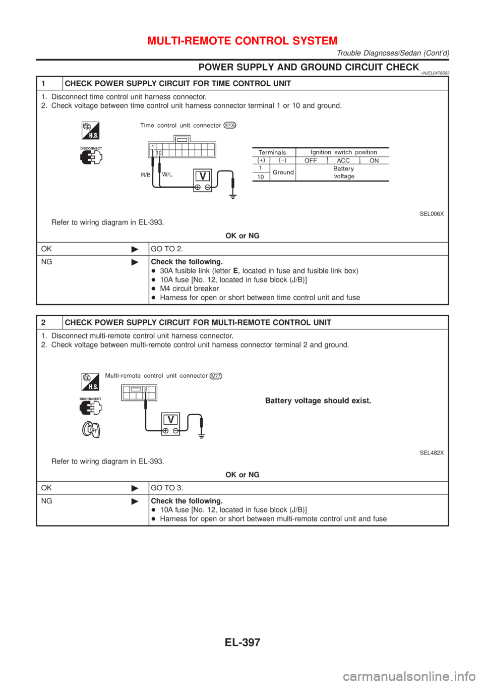
POWER SUPPLY AND GROUND CIRCUIT CHECK=NJEL0478S03
1 CHECK POWER SUPPLY CIRCUIT FOR TIME CONTROL UNIT
1. Disconnect time control unit harness connector.
2. Check voltage between time control unit harness connector terminal 1 or 10 and ground.
SEL006X
Refer to wiring diagram in EL-393.
OK or NG
OK©GO TO 2.
NG©Check the following.
+30A fusible link (letterE, located in fuse and fusible link box)
+10A fuse [No. 12, located in fuse block (J/B)]
+M4 circuit breaker
+Harness for open or short between time control unit and fuse
2 CHECK POWER SUPPLY CIRCUIT FOR MULTI-REMOTE CONTROL UNIT
1. Disconnect multi-remote control unit harness connector.
2. Check voltage between multi-remote control unit harness connector terminal 2 and ground.
SEL482X
Refer to wiring diagram in EL-393.
OK or NG
OK©GO TO 3.
NG©Check the following.
+10A fuse [No. 12, located in fuse block (J/B)]
+Harness for open or short between multi-remote control unit and fuse
MULTI-REMOTE CONTROL SYSTEM
Trouble Diagnoses/Sedan (Cont'd)
EL-397
Page 1956 of 2898
3 CHECK IGNITION SWITCH ªONº CIRCUIT
1. Disconnect multi-remote control unit harness connector.
2. Check voltage between multi-remote control unit terminal 4 and ground while ignition switch is ªONº.
SEL483X
Refer to wiring diagram in EL-393.
OK or NG
OK©GO TO 4.
NG©Check the following.
+10A fuse [No. 10, located in fuse block (J/B)]
+Harness for open or short between multi-remote control unit and fuse.
4 CHECK GROUND CIRCUIT FOR TIME CONTROL UNIT
Check continuity between time control unit harness connector terminal 16 and ground.
SEL992W
OK or NG
OK©GO TO 5.
NG©Check ground harness.
MULTI-REMOTE CONTROL SYSTEM
Trouble Diagnoses/Sedan (Cont'd)
EL-398