Page 2254 of 2898
CAUTION:
+When installing camshafts, chain tensioners, oil seals, or
other sliding parts, lubricate contacting surfaces with new
engine oil.
+Apply new engine oil to threads and seat surfaces when
installing cylinder head, camshaft sprocket, crankshaft
pulley, and camshaft bracket.
+Attach tags to valve lifters so as not to mix them up.
RemovalNJEM0063PREPARATIVE WORKNJEM0063S011. Drain engine coolant. Refer to LC-44, ªChanging Engine Cool-
antº.
2. Remove exhaust manifold. Refer to EM-112, ªRemovalº.
3. Remove intake manifold. Refer to EM-108, ªRemovalº.
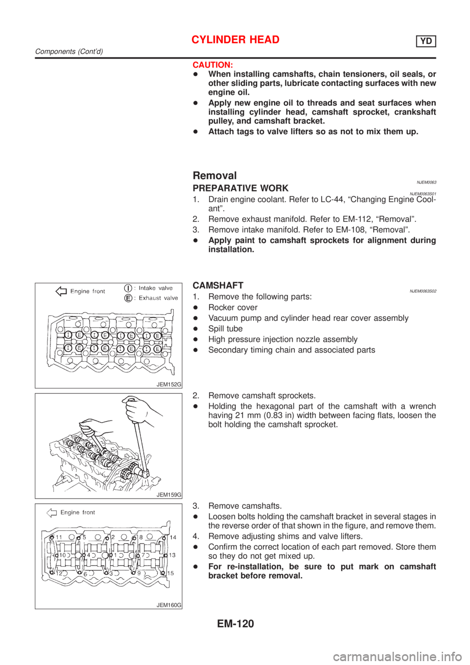
+Apply paint to camshaft sprockets for alignment during
installation.
JEM152G
CAMSHAFTNJEM0063S021. Remove the following parts:
+Rocker cover
+Vacuum pump and cylinder head rear cover assembly
+Spill tube
+High pressure injection nozzle assembly
+Secondary timing chain and associated parts
JEM159G
2. Remove camshaft sprockets.
+Holding the hexagonal part of the camshaft with a wrench
having 21 mm (0.83 in) width between facing flats, loosen the
bolt holding the camshaft sprocket.
JEM160G
3. Remove camshafts.
+Loosen bolts holding the camshaft bracket in several stages in
the reverse order of that shown in the figure, and remove them.
4. Remove adjusting shims and valve lifters.
+Confirm the correct location of each part removed. Store them
so they do not get mixed up.
+For re-installation, be sure to put mark on camshaft
bracket before removal.
CYLINDER HEADYD
Components (Cont'd)
EM-120
Page 2256 of 2898
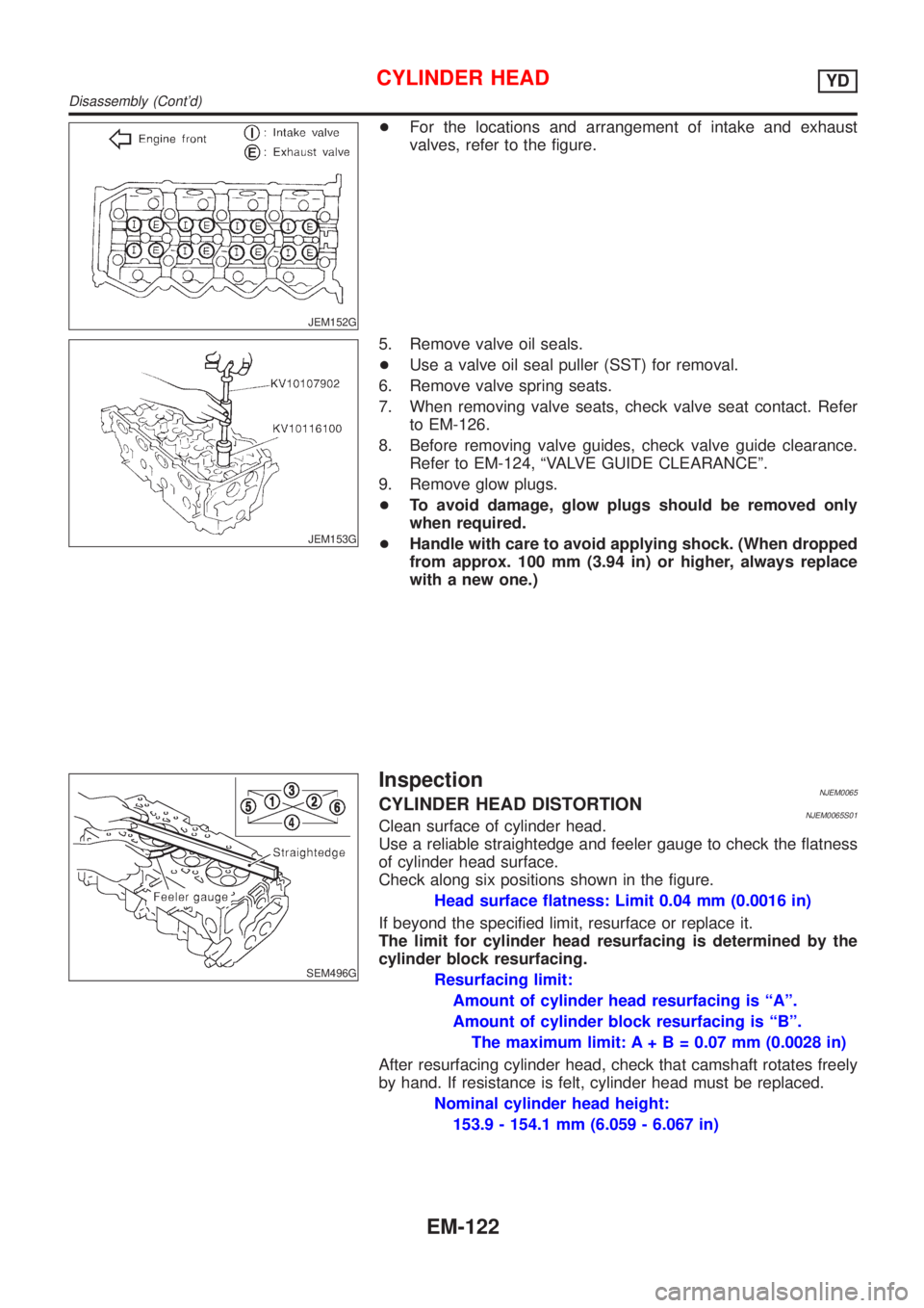
JEM152G
+For the locations and arrangement of intake and exhaust
valves, refer to the figure.
JEM153G
5. Remove valve oil seals.
+Use a valve oil seal puller (SST) for removal.
6. Remove valve spring seats.
7. When removing valve seats, check valve seat contact. Refer
to EM-126.
8. Before removing valve guides, check valve guide clearance.
Refer to EM-124, ªVALVE GUIDE CLEARANCEº.
9. Remove glow plugs.
+To avoid damage, glow plugs should be removed only
when required.
+Handle with care to avoid applying shock. (When dropped
from approx. 100 mm (3.94 in) or higher, always replace
with a new one.)
SEM496G
InspectionNJEM0065CYLINDER HEAD DISTORTIONNJEM0065S01Clean surface of cylinder head.
Use a reliable straightedge and feeler gauge to check the flatness
of cylinder head surface.
Check along six positions shown in the figure.
Head surface flatness: Limit 0.04 mm (0.0016 in)
If beyond the specified limit, resurface or replace it.
The limit for cylinder head resurfacing is determined by the
cylinder block resurfacing.
Resurfacing limit:
Amount of cylinder head resurfacing is ªAº.
Amount of cylinder block resurfacing is ªBº.
The maximum limit: A+ B = 0.07 mm (0.0028 in)
After resurfacing cylinder head, check that camshaft rotates freely
by hand. If resistance is felt, cylinder head must be replaced.
Nominal cylinder head height:
153.9 - 154.1 mm (6.059 - 6.067 in)
CYLINDER HEADYD
Disassembly (Cont'd)
EM-122
Page 2259 of 2898
SEM008A
VALVE GUIDE REPLACEMENTNJEM0065S09+When a valve guide is removed, replace with an oversized [0.2
mm (0.008 in)] valve guide.
1. To remove valve guide, heat cylinder head to 110 to 130ÉC
(230 to 266ÉF) by soaking in heated oil.
SEM931C
2. Drive out valve guide with a press [under a 20 kN (2 ton, 2.2
US ton, 2.0 Imp ton) pressure] or hammer and suitable tool.
SEM932C
3. Ream cylinder head valve guide hole.
Valve guide hole diameter (for service parts):
10.175 - 10.196 mm (0.4006 - 0.4014 in)
JEM156G
4. Heat cylinder head to 110 to 130ÉC (230 to 266ÉF) and press
service valve guide onto cylinder head.
Projection ªLº:
10.4 - 10.6 mm (0.409 - 0.417 in)
5. Ream valve guide.
Finished size:
6.000 - 6.018 mm (0.2362 - 0.2369 in)
CYLINDER HEADYD
Inspection (Cont'd)
EM-125
Page 2261 of 2898
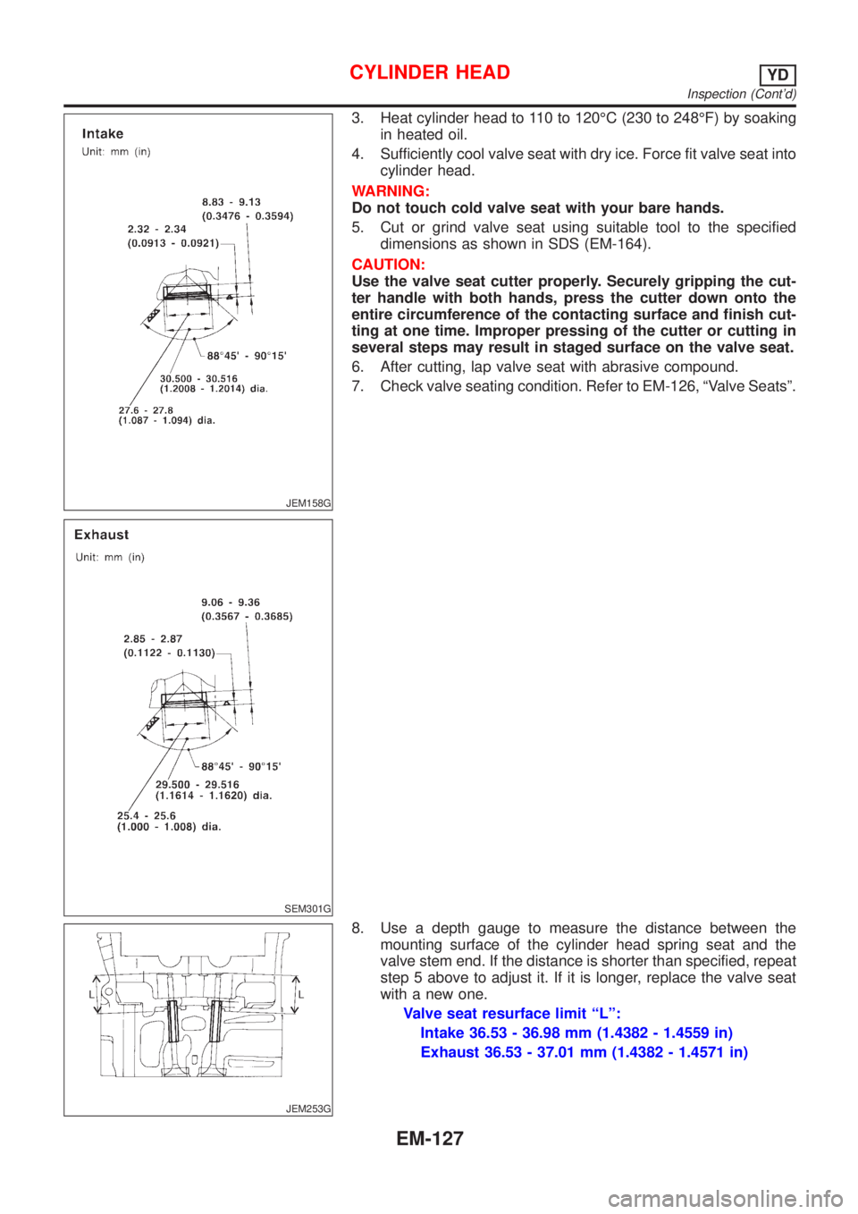
JEM158G
SEM301G
3. Heat cylinder head to 110 to 120ÉC (230 to 248ÉF) by soaking
in heated oil.
4. Sufficiently cool valve seat with dry ice. Force fit valve seat into
cylinder head.
WARNING:
Do not touch cold valve seat with your bare hands.
5. Cut or grind valve seat using suitable tool to the specified
dimensions as shown in SDS (EM-164).
CAUTION:
Use the valve seat cutter properly. Securely gripping the cut-
ter handle with both hands, press the cutter down onto the
entire circumference of the contacting surface and finish cut-
ting at one time. Improper pressing of the cutter or cutting in
several steps may result in staged surface on the valve seat.
6. After cutting, lap valve seat with abrasive compound.
7. Check valve seating condition. Refer to EM-126, ªValve Seatsº.
JEM253G
8. Use a depth gauge to measure the distance between the
mounting surface of the cylinder head spring seat and the
valve stem end. If the distance is shorter than specified, repeat
step 5 above to adjust it. If it is longer, replace the valve seat
with a new one.
Valve seat resurface limit ªLº:
Intake 36.53 - 36.98 mm (1.4382 - 1.4559 in)
Exhaust 36.53 - 37.01 mm (1.4382 - 1.4571 in)
CYLINDER HEADYD
Inspection (Cont'd)
EM-127
Page 2263 of 2898
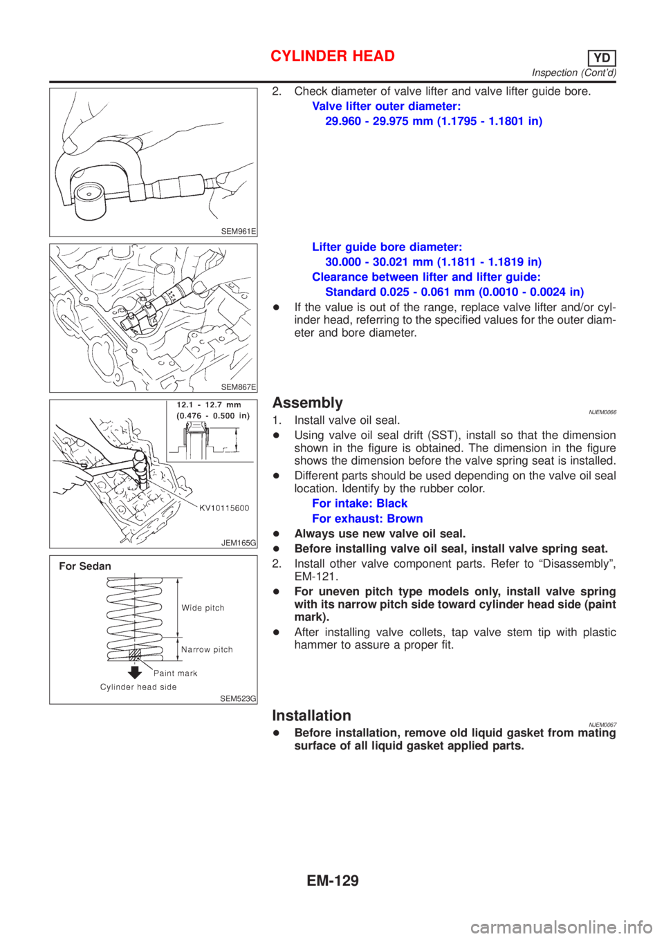
SEM961E
2. Check diameter of valve lifter and valve lifter guide bore.
Valve lifter outer diameter:
29.960 - 29.975 mm (1.1795 - 1.1801 in)
SEM867E
Lifter guide bore diameter:
30.000 - 30.021 mm (1.1811 - 1.1819 in)
Clearance between lifter and lifter guide:
Standard 0.025 - 0.061 mm (0.0010 - 0.0024 in)
+If the value is out of the range, replace valve lifter and/or cyl-
inder head, referring to the specified values for the outer diam-
eter and bore diameter.
JEM165G
SEM523G
AssemblyNJEM00661. Install valve oil seal.
+Using valve oil seal drift (SST), install so that the dimension
shown in the figure is obtained. The dimension in the figure
shows the dimension before the valve spring seat is installed.
+Different parts should be used depending on the valve oil seal
location. Identify by the rubber color.
For intake: Black
For exhaust: Brown
+Always use new valve oil seal.
+Before installing valve oil seal, install valve spring seat.
2. Install other valve component parts. Refer to ªDisassemblyº,
EM-121.
+For uneven pitch type models only, install valve spring
with its narrow pitch side toward cylinder head side (paint
mark).
+After installing valve collets, tap valve stem tip with plastic
hammer to assure a proper fit.
InstallationNJEM0067+Before installation, remove old liquid gasket from mating
surface of all liquid gasket applied parts.
CYLINDER HEADYD
Inspection (Cont'd)
EM-129
Page 2265 of 2898
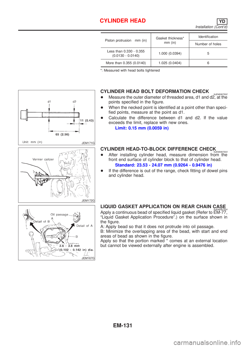
Piston protrusion mm (in)Gasket thickness*
mm (in)Identification
Number of holes
Less than 0.330 - 0.355
(0.0130 - 0.0140)1.000 (0.0394) 5
More than 0.355 (0.0140) 1.025 (0.0404) 6
*: Measured with head bolts tightened
JEM171G
CYLINDER HEAD BOLT DEFORMATION CHECKNJEM0067S02+Measure the outer diameter of threaded area, d1 and d2, at the
points specified in the figure.
+When the necked point is identified at a point other than speci-
fied points, measure at the point as d1.
+Calculate the difference between d1 and d2. If the value
exceeds the limit, replace with new ones.
Limit: 0.15 mm (0.0059 in)
JEM172G
CYLINDER HEAD-TO-BLOCK DIFFERENCE CHECKNJEM0067S03+After installing cylinder head, measure dimension from the
front end surface of cylinder block to that of cylinder head.
Standard: 23.53 - 24.07 mm (0.9264 - 0.9476 in)
+If the difference is out of the range, check fitting of dowel pins
and cylinder head.
JEM167G
LIQUID GASKET APPLICATION ON REAR CHAIN CASENJEM0067S04Apply a continuous bead of specified liquid gasket (Refer to EM-77,
ªLiquid Gasket Application Procedureº.) on the surface shown in
the figure.
A: Apply bead so that it does not protrude into oil passage.
B: Minimize the overlapping area of the bead, with start and end
areas of bead as shown in the figure.
Apply so that the portion marked * comes at an external location
but cannot be viewed externally after engine is assembled.
CYLINDER HEADYD
Installation (Cont'd)
EM-131
Page 2266 of 2898
JEM149G
JEM166G
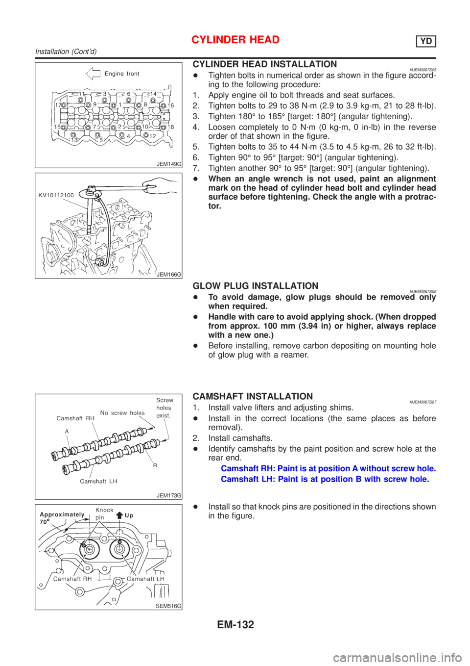
CYLINDER HEAD INSTALLATIONNJEM0067S05+Tighten bolts in numerical order as shown in the figure accord-
ing to the following procedure:
1. Apply engine oil to bolt threads and seat surfaces.
2. Tighten bolts to 29 to 38 N´m (2.9 to 3.9 kg-m, 21 to 28 ft-lb).
3. Tighten 180É to 185É [target: 180É] (angular tightening).
4. Loosen completely to 0 N´m (0 kg-m, 0 in-lb) in the reverse
order of that shown in the figure.
5. Tighten bolts to 35 to 44 N´m (3.5 to 4.5 kg-m, 26 to 32 ft-lb).
6. Tighten 90É to 95É [target: 90É] (angular tightening).
7. Tighten another 90É to 95É [target: 90É] (angular tightening).
+When an angle wrench is not used, paint an alignment
mark on the head of cylinder head bolt and cylinder head
surface before tightening. Check the angle with a protrac-
tor.
GLOW PLUG INSTALLATIONNJEM0067S06+To avoid damage, glow plugs should be removed only
when required.
+Handle with care to avoid applying shock. (When dropped
from approx. 100 mm (3.94 in) or higher, always replace
with a new one.)
+Before installing, remove carbon depositing on mounting hole
of glow plug with a reamer.
JEM173G
CAMSHAFT INSTALLATIONNJEM0067S071. Install valve lifters and adjusting shims.
+Install in the correct locations (the same places as before
removal).
2. Install camshafts.
+Identify camshafts by the paint position and screw hole at the
rear end.
Camshaft RH: Paint is at position A without screw hole.
Camshaft LH: Paint is at position B with screw hole.
SEM516G
+Install so that knock pins are positioned in the directions shown
in the figure.
CYLINDER HEADYD
Installation (Cont'd)
EM-132
Page 2267 of 2898
JEM175G
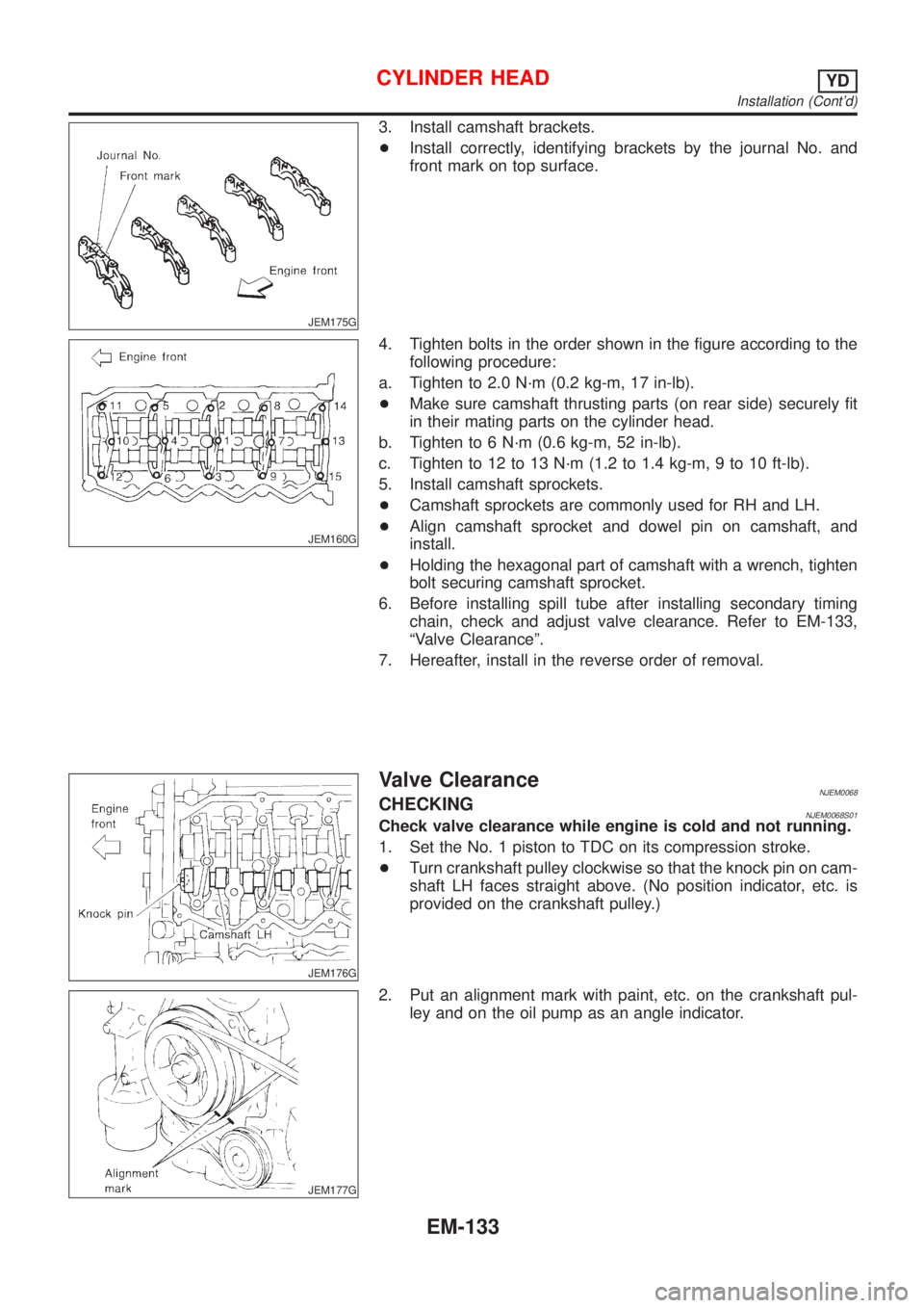
3. Install camshaft brackets.
+Install correctly, identifying brackets by the journal No. and
front mark on top surface.
JEM160G
4. Tighten bolts in the order shown in the figure according to the
following procedure:
a. Tighten to 2.0 N´m (0.2 kg-m, 17 in-lb).
+Make sure camshaft thrusting parts (on rear side) securely fit
in their mating parts on the cylinder head.
b. Tighten to 6 N´m (0.6 kg-m, 52 in-lb).
c. Tighten to 12 to 13 N´m (1.2 to 1.4 kg-m, 9 to 10 ft-lb).
5. Install camshaft sprockets.
+Camshaft sprockets are commonly used for RH and LH.
+Align camshaft sprocket and dowel pin on camshaft, and
install.
+Holding the hexagonal part of camshaft with a wrench, tighten
bolt securing camshaft sprocket.
6. Before installing spill tube after installing secondary timing
chain, check and adjust valve clearance. Refer to EM-133,
ªValve Clearanceº.
7. Hereafter, install in the reverse order of removal.
JEM176G
Valve ClearanceNJEM0068CHECKINGNJEM0068S01Check valve clearance while engine is cold and not running.
1. Set the No. 1 piston to TDC on its compression stroke.
+Turn crankshaft pulley clockwise so that the knock pin on cam-
shaft LH faces straight above. (No position indicator, etc. is
provided on the crankshaft pulley.)
JEM177G
2. Put an alignment mark with paint, etc. on the crankshaft pul-
ley and on the oil pump as an angle indicator.
CYLINDER HEADYD
Installation (Cont'd)
EM-133