Page 77 of 2898
DIAGNOSTIC WORKSHEET=NJAT0257S01Information from CustomerNJAT0257S0101KEY POINTS
WHAT..... Vehicle & A/T model
WHEN..... Date, Frequencies
WHERE..... Road conditions
HOW..... Operating conditions, Symptoms
Customer name MR/MS Model & Year VIN
Trans. model Engine Mileage
Incident Date Manuf. Date In Service Date
FrequencyNContinuousNIntermittent ( times a day)
SymptomsNVehicle does not move. (NAny positionNParticular position)
NNo up-shift (N1st®2ndN2nd®3rdN3rd®O/D)
NNo down-shift (NO/D®3rdN3rd®2ndN2nd®1st)
NLockup malfunction
NShift point too high or too low.
NShift shock or slip (NN®DNLockupNAny drive position)
NNoise or vibration
NNo kickdown
NNo pattern select
NOthers
()
O/D OFF indicator lamp Blinks for about 8 seconds.
NContinuously litNNot lit
Malfunction indicator (MI)NContinuously litNNot lit
TROUBLE DIAGNOSIS Ð INTRODUCTIONEURO-OBD
Introduction (Cont'd)
AT-75
Page 307 of 2898

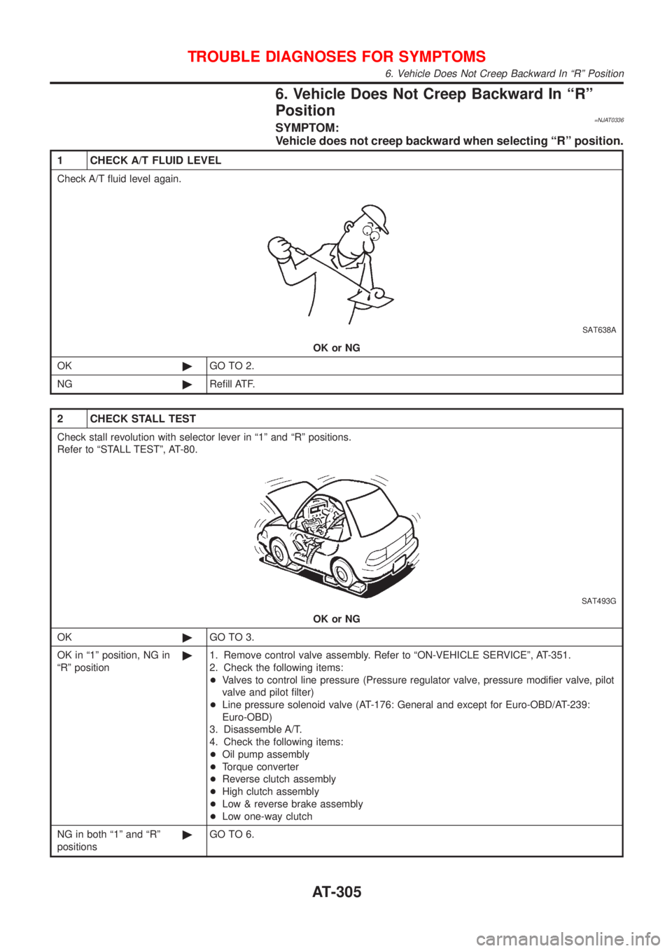
6. Vehicle Does Not Creep Backward In ªRº
Position
=NJAT0336SYMPTOM:
Vehicle does not creep backward when selecting ªRº position.
1 CHECK A/T FLUID LEVEL
Check A/T fluid level again.
SAT638A
OK or NG
OK©GO TO 2.
NG©Refill ATF.
2 CHECK STALL TEST
Check stall revolution with selector lever in ª1º and ªRº positions.
Refer to ªSTALL TESTº, AT-80.
SAT493G
OK or NG
OK©GO TO 3.
OK in ª1º position, NG in
ªRº position©1. Remove control valve assembly. Refer to ªON-VEHICLE SERVICEº, AT-351.
2. Check the following items:
+Valves to control line pressure (Pressure regulator valve, pressure modifier valve, pilot
valve and pilot filter)
+Line pressure solenoid valve (AT-176: General and except for Euro-OBD/AT-239:
Euro-OBD)
3. Disassemble A/T.
4. Check the following items:
+Oil pump assembly
+Torque converter
+Reverse clutch assembly
+High clutch assembly
+Low & reverse brake assembly
+Low one-way clutch
NG in both ª1º and ªRº
positions©GO TO 6.
TROUBLE DIAGNOSES FOR SYMPTOMS
6. Vehicle Does Not Creep Backward In ªRº Position
AT-305
Page 308 of 2898
3 CHECK LINE PRESSURE
Check line pressure at idle with selector lever in ªRº position. Refer to ªLine Pressure Testº, AT-84.
SAT494G
OK or NG
OK©GO TO 4.
NG©1. Remove control valve assembly. Refer to ªON-VEHICLE SERVICEº, AT-351.
2. Check the following items:
+Valves to control line pressure (Pressure regulator valve, pressure modifier valve, pilot
valve and pilot filter)
+Line pressure solenoid valve (AT-176: General and except for Euro-OBD/AT-239:
Euro-OBD)
3. Disassemble A/T.
4. Check the following item:
+Oil pump assembly
4 CHECK A/T FLUID CONDITION
1. Remove oil pan.
2. Check A/T fluid condition.
SAT171B
OK or NG
OK©GO TO 5.
NG©GO TO 6.
5 CHECK SYMPTOM
Check again.
OK or NG
OK©INSPECTION END
NG©1. Perform TCM input/output signal inspection.
2. If NG, recheck TCM pin terminals for damage or loose connection with harness con-
nector.
TROUBLE DIAGNOSES FOR SYMPTOMS
6. Vehicle Does Not Creep Backward In ªRº Position (Cont'd)
AT-306
Page 309 of 2898
6 DETECT MALFUNCTIONING ITEM
1. Remove control valve assembly. Refer to ªON-VEHICLE SERVICEº, AT-351.
2. Check the following items:
+Valves to control line pressure (Pressure regulator valve, pressure modifier valve, pilot valve and pilot filter)
+Line pressure solenoid valve (AT-176: General and except for Euro-OBD/AT-239: Euro-OBD)
3. Disassemble A/T.
4. Check the following items:
+Oil pump assembly
+Torque converter
+Reverse clutch assembly
+High clutch assembly
+Low & reverse brake assembly
+Low one-way clutch
OK or NG
OK©GO TO 5.
NG©Repair or replace damaged parts.
TROUBLE DIAGNOSES FOR SYMPTOMS
6. Vehicle Does Not Creep Backward In ªRº Position (Cont'd)
AT-307
Page 347 of 2898

Diagnostic ProcedureNJAT0105SYMPTOM 1:
+Selector lever cannot be moved from ªPº position with key
in ON position and brake pedal applied.
+Selector lever can be moved from ªPº position with key in
ON position and brake pedal released.
+Selector lever can be moved from ªPº position when key
is removed from key cylinder.
SYMPTOM 2:
Ignition key cannot be removed when selector lever is set to
ªPº position. It can be removed when selector lever is set to
any position except ªPº.
1 CHECK KEY INTERLOCK CABLE
Check key interlock cable for damage.
OK or NG
OK©GO TO 2.
NG©Repair key interlock cable. Refer to AT-349.
2 CHECK SELECTOR LEVER POSITION
Check selector lever position for damage.
OK or NG
OK©GO TO 3.
NG©Check selector lever. Refer to ªON-VEHICLE SERVICE Ð PNP Switch and Control
Cable Adjustmentº, AT-352.
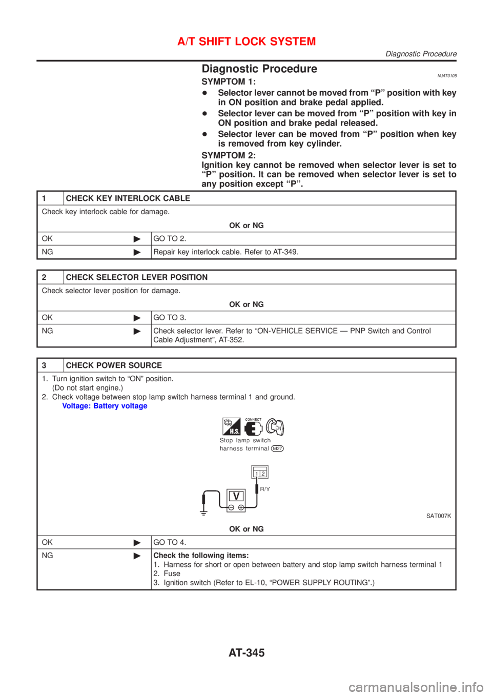
3 CHECK POWER SOURCE
1. Turn ignition switch to ªONº position.
(Do not start engine.)
2. Check voltage between stop lamp switch harness terminal 1 and ground.
Voltage: Battery voltage
SAT007K
OK or NG
OK©GO TO 4.
NG©Check the following items:
1. Harness for short or open between battery and stop lamp switch harness terminal 1
2. Fuse
3. Ignition switch (Refer to EL-10, ªPOWER SUPPLY ROUTINGº.)
A/T SHIFT LOCK SYSTEM
Diagnostic Procedure
AT-345
Page 353 of 2898
SAT992C
Control Valve Assembly and AccumulatorsNJAT0110REMOVALNJAT0110S011. Drain ATF from transaxle.
2. Remove oil pan and gasket.
SAT064K
3. Disconnect A/T solenoid valve harness connector.
AAT265A
4. Remove stopper ring from A/T solenoid harness terminal body.
5. Remove A/T solenoid harness by pushing terminal body into
transmission case.
AAT260A
6. Remove control valve assembly by removing fixing bolts.
Bolt length, number and location:
Bolt symbol A B C
Bolt length ª!º
40.0 mm
(1.575 in)33.0 mm
(1.299 in)43.5 mm
(1.713 in)
Number of bolts 5 6 2
+Be careful not to drop manual valve and servo release
accumulator return springs.
7. Disassemble and inspect control valve assembly if necessary.
Refer to AT-366.
ON-VEHICLE SERVICE
Control Valve Assembly and Accumulators
AT-351
Page 354 of 2898

SAT935J
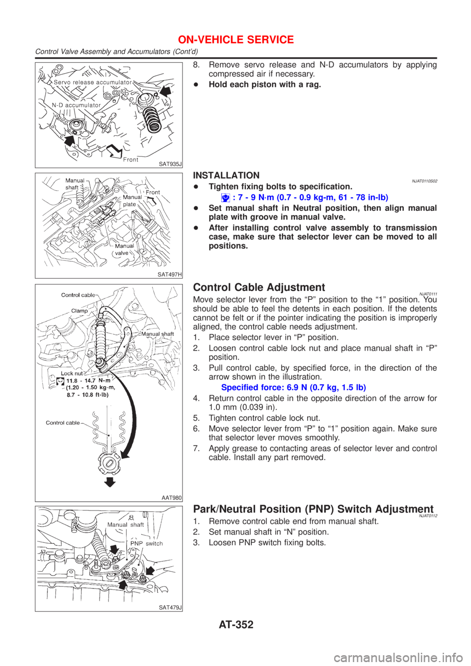
8. Remove servo release and N-D accumulators by applying
compressed air if necessary.
+Hold each piston with a rag.
SAT497H
INSTALLATIONNJAT0110S02+Tighten fixing bolts to specification.
:7-9N´m(0.7 - 0.9 kg-m, 61 - 78 in-lb)
+Set manual shaft in Neutral position, then align manual
plate with groove in manual valve.
+After installing control valve assembly to transmission
case, make sure that selector lever can be moved to all
positions.
AAT980
Control Cable AdjustmentNJAT0111Move selector lever from the ªPº position to the ª1º position. You
should be able to feel the detents in each position. If the detents
cannot be felt or if the pointer indicating the position is improperly
aligned, the control cable needs adjustment.
1. Place selector lever in ªPº position.
2. Loosen control cable lock nut and place manual shaft in ªPº
position.
3. Pull control cable, by specified force, in the direction of the
arrow shown in the illustration.
Specified force: 6.9 N (0.7 kg, 1.5 lb)
4. Return control cable in the opposite direction of the arrow for
1.0 mm (0.039 in).
5. Tighten control cable lock nut.
6. Move selector lever from ªPº to ª1º position again. Make sure
that selector lever moves smoothly.
7. Apply grease to contacting areas of selector lever and control
cable. Install any part removed.
SAT479J
Park/Neutral Position (PNP) Switch AdjustmentNJAT01121. Remove control cable end from manual shaft.
2. Set manual shaft in ªNº position.
3. Loosen PNP switch fixing bolts.
ON-VEHICLE SERVICE
Control Valve Assembly and Accumulators (Cont'd)
AT-352
Page 355 of 2898

SAT480J
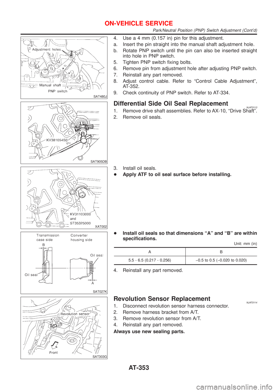
4. Usea4mm(0.157 in) pin for this adjustment.
a. Insert the pin straight into the manual shaft adjustment hole.
b. Rotate PNP switch until the pin can also be inserted straight
into hole in PNP switch.
5. Tighten PNP switch fixing bolts.
6. Remove pin from adjustment hole after adjusting PNP switch.
7. Reinstall any part removed.
8. Adjust control cable. Refer to ªControl Cable Adjustmentº,
AT-352.
9. Check continuity of PNP switch. Refer to AT-334.
SAT905DB
Differential Side Oil Seal ReplacementNJAT01131. Remove drive shaft assemblies. Refer to AX-10, ªDrive Shaftº.
2. Remove oil seals.
XAT002
3. Install oil seals.
+Apply ATF to oil seal surface before installing.
SAT027K
+Install oil seals so that dimensions ªAº and ªBº are within
specifications.
Unit: mm (in)
AB
5.5 - 6.5 (0.217 - 0.256) þ0.5 to 0.5 (þ0.020 to 0.020)
4. Reinstall any part removed.
SAT303G
Revolution Sensor ReplacementNJAT01141. Disconnect revolution sensor harness connector.
2. Remove harness bracket from A/T.
3. Remove revolution sensor from A/T.
4. Reinstall any part removed.
Always use new sealing parts.
ON-VEHICLE SERVICE
Park/Neutral Position (PNP) Switch Adjustment (Cont'd)
AT-353