Page 1255 of 2898
7 CHECK VALVE TIMING CONTROL SOLENOID VALVE
Refer to ªComponent Inspectionº, EC-531.
OK or NG
OK©GO TO 8.
NG©Replace valve timing control solenoid valve.
8 CHECK INTERMITTENT INCIDENT
Perform ªTROUBLE DIAGNOSIS FOR INTERMITTENT INCIDENTº, EC-177.
©INSPECTION END
SEF159Y
Component InspectionNJEC1775INTAKE VALVE TIMING CONTROL SOLENOID VALVENJEC1775S011. Check oil passage visually for any metal debris.
2. Supply intake valve timing control solenoid valve terminals with
battery voltage.
3. Make sure that inside plunger protrudes.
If NG, replace intake valve timing control solenoid valve.
INTAKE VALVE TIMING CONTROL SOLENOID VALVEQG
Diagnostic Procedure (Cont'd)
EC-531
Page 1265 of 2898

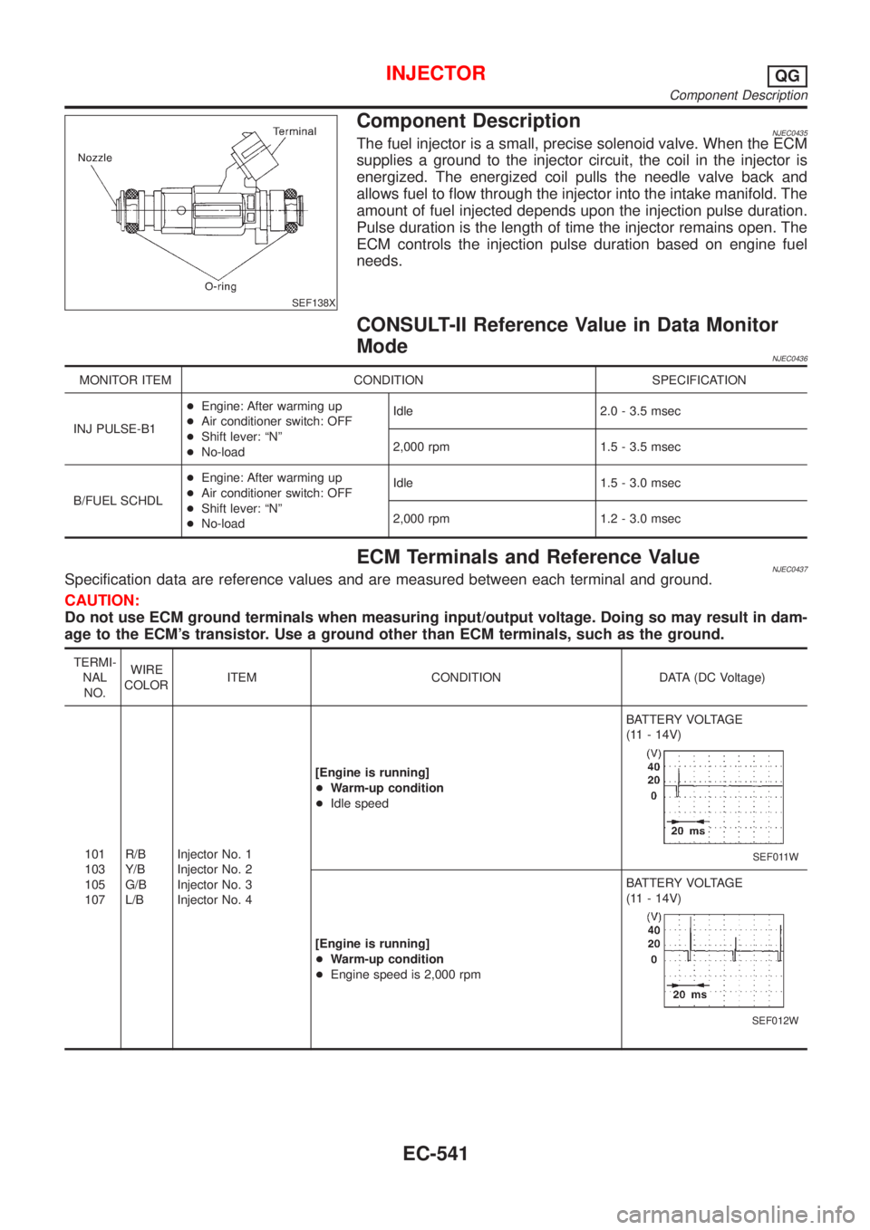
SEF138X
Component DescriptionNJEC0435The fuel injector is a small, precise solenoid valve. When the ECM
supplies a ground to the injector circuit, the coil in the injector is
energized. The energized coil pulls the needle valve back and
allows fuel to flow through the injector into the intake manifold. The
amount of fuel injected depends upon the injection pulse duration.
Pulse duration is the length of time the injector remains open. The
ECM controls the injection pulse duration based on engine fuel
needs.
CONSULT-II Reference Value in Data Monitor
Mode
NJEC0436
MONITOR ITEM CONDITION SPECIFICATION
INJ PULSE-B1+Engine: After warming up
+Air conditioner switch: OFF
+Shift lever: ªNº
+No-loadIdle 2.0 - 3.5 msec
2,000 rpm 1.5 - 3.5 msec
B/FUEL SCHDL+Engine: After warming up
+Air conditioner switch: OFF
+Shift lever: ªNº
+No-loadIdle 1.5 - 3.0 msec
2,000 rpm 1.2 - 3.0 msec
ECM Terminals and Reference ValueNJEC0437Specification data are reference values and are measured between each terminal and ground.
CAUTION:
Do not use ECM ground terminals when measuring input/output voltage. Doing so may result in dam-
age to the ECM's transistor. Use a ground other than ECM terminals, such as the ground.
TERMI-
NAL
NO.WIRE
COLORITEM CONDITION DATA (DC Voltage)
101
103
105
107R/B
Y/B
G/B
L/BInjector No. 1
Injector No. 2
Injector No. 3
Injector No. 4[Engine is running]
+Warm-up condition
+Idle speedBATTERY VOLTAGE
(11 - 14V)
SEF011W
[Engine is running]
+Warm-up condition
+Engine speed is 2,000 rpmBATTERY VOLTAGE
(11 - 14V)
SEF012W
INJECTORQG
Component Description
EC-541
Page 1271 of 2898

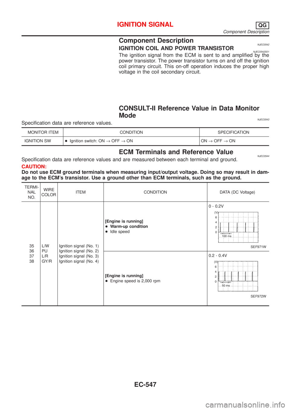
Component DescriptionNJEC0542IGNITION COIL AND POWER TRANSISTORNJEC0542S01The ignition signal from the ECM is sent to and amplified by the
power transistor. The power transistor turns on and off the ignition
coil primary circuit. This on-off operation induces the proper high
voltage in the coil secondary circuit.
CONSULT-II Reference Value in Data Monitor
Mode
NJEC0543Specification data are reference values.
MONITOR ITEM CONDITION SPECIFICATION
IGNITION SW+Ignition switch: ON®OFF®ON ON®OFF®ON
ECM Terminals and Reference ValueNJEC0544Specification data are reference values and are measured between each terminal and ground.
CAUTION:
Do not use ECM ground terminals when measuring input/output voltage. Doing so may result in dam-
age to the ECM's transistor. Use a ground other than ECM terminals, such as the ground.
TERMI-
NAL
NO.WIRE
COLORITEM CONDITION DATA (DC Voltage)
35
36
37
38L/W
PU
L/R
GY/RIgnition signal (No. 1)
Ignition signal (No. 2)
Ignition signal (No. 3)
Ignition signal (No. 4)[Engine is running]
+Warm-up condition
+Idle speed0 - 0.2V
SEF971W
[Engine is running]
+Engine speed is 2,000 rpm0.2 - 0.4V
SEF972W
IGNITION SIGNALQG
Component Description
EC-547
Page 1275 of 2898
Diagnostic ProcedureNJEC0579
1 CHECK ENGINE START
Turn ignition switch ªOFFº, and restart engine.
Is engine running?
YesorNo
Yes (With CONSULT-II)©GO TO 2.
Yes (Without CONSULT-
II)©GO TO 12.
No©GO TO 3.
2 SEARCH FOR MALFUNCTIONING CIRCUIT
With CONSULT-II
1. Perform ªPOWER BALANCEº in ªACTIVE TESTº mode with CONSULT-II.
2. Search for circuit which does not produce a momentary engine speed drop.
SEF190Y
©GO TO 12.
3 CHECK IGNITION COIL POWER SUPPLY CIRCUIT-I
1. Turn ignition switch ON.
2. Check voltage between ECM terminals 110, 112 and ground with CONSULT-II or tester.
SEF366X
OK or NG
OK©GO TO 4.
NG©GO TO TROUBLE DIAGNOSIS FOR POWER SUPPLY, EC-178.
IGNITION SIGNALQG
Diagnostic Procedure
EC-551
Page 1276 of 2898
4 CHECK IGNITION COIL POWER SUPPLY CIRCUIT-II
1. Turn ignition switch OFF.
2. Disconnect condenser harness connector.
JEF121Y
3. Turn ignition switch ON.
4. Check voltage between condenser terminal 1 and ground with CONSULT-II or tester.
SEF367X
OK or NG
OK©GO TO 10.
NG©GO TO 5.
5 CHECK IGNITION COIL POWER SUPPLY CIRCUIT-III
1. Turn ignition switch OFF.
2. Disconnect ECM relay. (For ECM relay location, refer to ªEngine Control Component Parts Locationº.)
3. Check harness continuity between ECM relay terminal 7 and condenser terminal 1. Refer to Wiring Diagram.
Continuity should exist.
4. Also check harness for short to ground and short to power.
OK or NG
OK©GO TO 7.
NG©GO TO 6.
6 DETECT MALFUNCTIONING PART
Check the harness for open or short between ECM relay and condenser.
©Repair open circuit or short to ground or short to power in harness or connectors.
IGNITION SIGNALQG
Diagnostic Procedure (Cont'd)
EC-552
Page 1277 of 2898

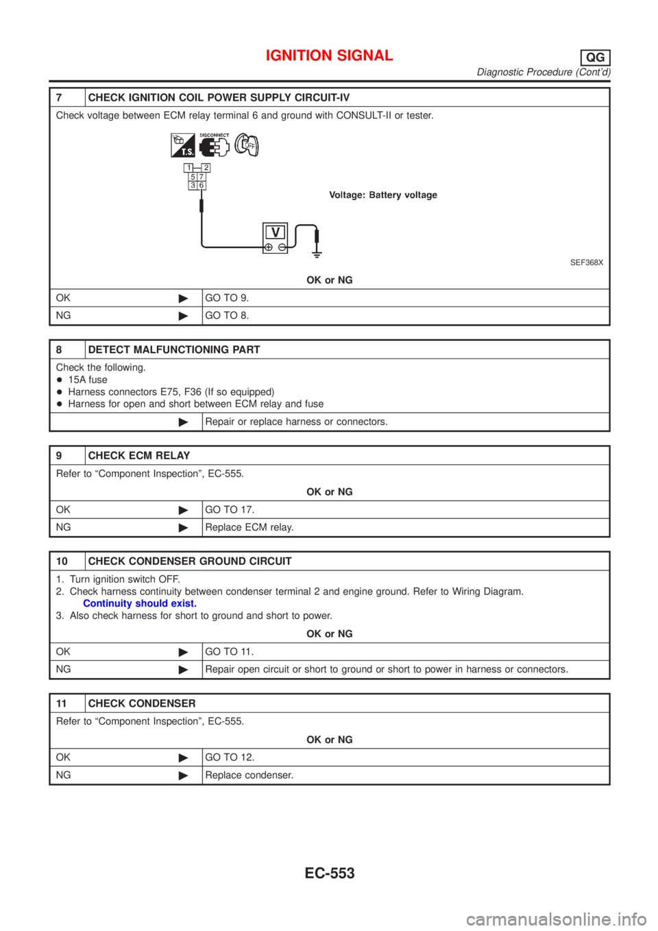
7 CHECK IGNITION COIL POWER SUPPLY CIRCUIT-IV
Check voltage between ECM relay terminal 6 and ground with CONSULT-II or tester.
SEF368X
OK or NG
OK©GO TO 9.
NG©GO TO 8.
8 DETECT MALFUNCTIONING PART
Check the following.
+15A fuse
+Harness connectors E75, F36 (If so equipped)
+Harness for open and short between ECM relay and fuse
©Repair or replace harness or connectors.
9 CHECK ECM RELAY
Refer to ªComponent Inspectionº, EC-555.
OK or NG
OK©GO TO 17.
NG©Replace ECM relay.
10 CHECK CONDENSER GROUND CIRCUIT
1. Turn ignition switch OFF.
2. Check harness continuity between condenser terminal 2 and engine ground. Refer to Wiring Diagram.
Continuity should exist.
3. Also check harness for short to ground and short to power.
OK or NG
OK©GO TO 11.
NG©Repair open circuit or short to ground or short to power in harness or connectors.
11 CHECK CONDENSER
Refer to ªComponent Inspectionº, EC-555.
OK or NG
OK©GO TO 12.
NG©Replace condenser.
IGNITION SIGNALQG
Diagnostic Procedure (Cont'd)
EC-553
Page 1278 of 2898
12 CHECK IGNITION COIL POWER SUPPLY CIRCUIT-V
1. Turn ignition switch OFF.
2. Reconnect harness connectors disconnected.
3. Disconnect ignition coil harness connector.
JEF119Y
4. Turn ignition switch ON.
5. Check voltage between ignition coil terminal 1 and ground with CONSULT-II or tester.
SEF122Y
OK or NG
OK©GO TO 14.
NG©GO TO 13.
13 DETECT MALFUNCTIONING PART
Check the following.
+Harness connector E75, F36 (If so equipped)
+Harness for open or short between ignition coil and ECM relay terminal 7
©Repair or replace harness or connectors.
14 CHECK IGNITION COIL GROUND CIRCUIT
1. Turn ignition switch OFF.
2. Check harness continuity between ignition coil terminal 2 and engine ground. Refer to Wiring Diagram.
Continuity should exist.
3. Also check harness for short to ground and short to power.
OK or NG
OK©GO TO 15.
NG©Repair open circuit or short to ground or short to power in harness or connectors.
IGNITION SIGNALQG
Diagnostic Procedure (Cont'd)
EC-554
Page 1279 of 2898

15 CHECK IGNITION COIL OUTPUT SIGNAL CIRCUIT
1. Disconnect ECM harness connector.
2. Check harness continuity between ECM terminals 35, 36, 37, 38 and ignition coil terminal 3. Refer to Wiring Diagram.
Continuity should exist.
3. Also check harness for short to ground and short to power.
OK or NG
OK©GO TO 16.
NG©Repair open circuit or short to ground or short to power in harness or connectors.
16 CHECK IGNITION COIL WITH POWER TRANSISTOR
Refer to ªComponent Inspectionº, EC-555.
OK or NG
OK©GO TO 17.
NG©Replace ignition coil with power transistor.
17 CHECK INTERMITTENT INCIDENT
Refer to ªTROUBLE DIAGNOSIS FOR INTERMITTENT INCIDENTº, EC-177.
©INSPECTION END
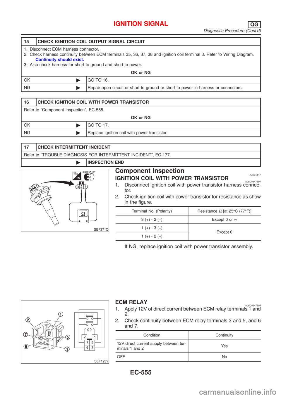
SEF371Q
Component InspectionNJEC0547IGNITION COIL WITH POWER TRANSISTORNJEC0547S011. Disconnect ignition coil with power transistor harness connec-
tor.
2. Check ignition coil with power transistor for resistance as show
in the figure.
Terminal No. (Polarity) ResistanceW[at 25ÉC (77ÉF)]
3 (+) - 2 (þ) Except 0 or¥
1 (+) - 3 (þ)
Except 0
1 (+) - 2 (þ)
If NG, replace ignition coil with power transistor assembly.
SEF123Y
ECM RELAYNJEC0547S031. Apply 12V of direct current between ECM relay terminals 1 and
2.
2. Check continuity between ECM relay terminals 3 and 5, and 6
and 7.
Condition Continuity
12V direct current supply between ter-
minals 1 and 2Ye s
OFF No
IGNITION SIGNALQG
Diagnostic Procedure (Cont'd)
EC-555