2001 NISSAN ALMERA water pump
[x] Cancel search: water pumpPage 1472 of 2898
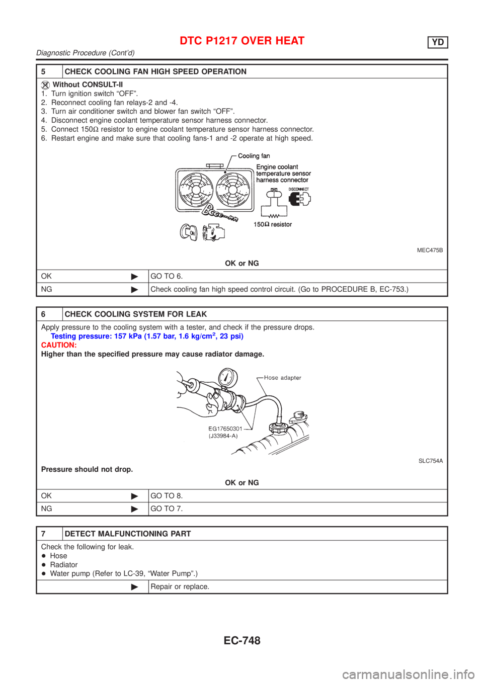
5 CHECK COOLING FAN HIGH SPEED OPERATION
Without CONSULT-II
1. Turn ignition switch ªOFFº.
2. Reconnect cooling fan relays-2 and -4.
3. Turn air conditioner switch and blower fan switch ªOFFº.
4. Disconnect engine coolant temperature sensor harness connector.
5. Connect 150Wresistor to engine coolant temperature sensor harness connector.
6. Restart engine and make sure that cooling fans-1 and -2 operate at high speed.
MEC475B
OK or NG
OK©GO TO 6.
NG©Check cooling fan high speed control circuit. (Go to PROCEDURE B, EC-753.)
6 CHECK COOLING SYSTEM FOR LEAK
Apply pressure to the cooling system with a tester, and check if the pressure drops.
Testing pressure: 157 kPa (1.57 bar, 1.6 kg/cm2, 23 psi)
CAUTION:
Higher than the specified pressure may cause radiator damage.
SLC754A
Pressure should not drop.
OK or NG
OK©GO TO 8.
NG©GO TO 7.
7 DETECT MALFUNCTIONING PART
Check the following for leak.
+Hose
+Radiator
+Water pump (Refer to LC-39, ªWater Pumpº.)
©Repair or replace.
DTC P1217 OVER HEATYD
Diagnostic Procedure (Cont'd)
EC-748
Page 1486 of 2898
Diagnostic ProcedureNJEC0733
1 INSPECTION START
1. Turn ignition switch ªOFFº.
2. Perform ªAIR BREEDINGº, EC-625, and ªWATER DRAININGº, EC-625.
©GO TO 2.
2 PERFORM DTC CONFIRMATION PROCEDURE AGAIN
Perform ªDTC Confirmation Procedureº, EC-758 again.
OK or NG
OK©INSPECTION END
NG©GO TO 3.
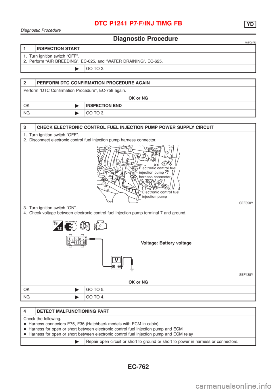
3 CHECK ELECTRONIC CONTROL FUEL INJECTION PUMP POWER SUPPLY CIRCUIT
1. Turn ignition switch ªOFFº.
2. Disconnect electronic control fuel injection pump harness connector.
SEF390Y
3. Turn ignition switch ªONº.
4. Check voltage between electronic control fuel injection pump terminal 7 and ground.
SEF438Y
OK or NG
OK©GO TO 5.
NG©GO TO 4.
4 DETECT MALFUNCTIONING PART
Check the following.
+Harness connectors E75, F36 (Hatchback models with ECM in cabin)
+Harness for open or short between electronic control fuel injection pump and ECM
+Harness for open or short between electronic control fuel injection pump and ECM relay
©Repair open circuit or short to ground or short to power in harness or connectors.
DTC P1241 P7´F/INJ TIMG FBYD
Diagnostic Procedure
EC-762
Page 2136 of 2898
REPLACEMENT OF CONNECTING ROD
BUSHING (SMALL END)
..........................................62
FLYWHEEL/DRIVE PLATE RUNOUT........................62
Assembly ...................................................................62
PISTON..................................................................62
CRANKSHAFT.........................................................63
SERVICE DATA AND SPECIFICATIONS (SDS).........66
General Specifications ...............................................66
Compression Pressure ..............................................66
Belt Deflection............................................................67
Spark Plug .................................................................67
Cylinder Head ............................................................67
Valve ..........................................................................68
VALVE....................................................................68
VALVE SPRING.......................................................68
VALVE LIFTER........................................................68
VALVE CLEARANCE................................................69
VALVE GUIDE.........................................................69
AVAILABLE SHIMS..................................................69
VALVE SEAT...........................................................71
VALVE SEAT RESURFACE LIMIT.............................72
Camshaft and Camshaft Bearing ..............................72
Cylinder Block ............................................................73
Piston, Piston Ring and Piston Pin ...........................74
PISTON..................................................................74
PISTON RING.........................................................74
PISTON PIN............................................................74
Connecting Rod .........................................................75
Crankshaft..................................................................75
Main Bearing..............................................................75
STANDARD.............................................................75
UNDERSIZE............................................................75
Connecting Rod Bearing ...........................................76
STANDARD SIZE....................................................76
UNDERSIZE............................................................76
Bearing Clearance .....................................................76
Miscellaneous Components.......................................76
YD
PRECAUTIONS.............................................................77
Parts Requiring Angular Tightening ...........................77
Liquid Gasket Application Procedure ........................77
PREPARATION.............................................................78
Special Service Tools ................................................78
Commercial Service Tools .........................................80
NOISE, VIBRATION AND HARSHNESS (NVH)
TROUBLESHOOTING...................................................82
NVH Troubleshooting - Engine Noise .......................82
MEASUREMENT OF COMPRESSION PRESSURE....83
DRIVE BELTS................................................................85
Inspection...................................................................85
Adjustment .................................................................85
AIR CONDITIONER COMPRESSOR BELT................86
ALTERNATOR & WATER PUMP BELT.....................86
Removal .....................................................................86
Installation ..................................................................87
AIR CLEANER...............................................................88
Changing Air Cleaner Filter .......................................88
VISCOUS PAPER TYPE...........................................88
OIL PAN.........................................................................89
Components...............................................................89
Removal .....................................................................89
Installation ..................................................................91
TIMING CHAIN..............................................................94
Secondary Timing Chain ...........................................94
REMOVAL...............................................................94
INSPECTION...........................................................96
INSTALLATION........................................................96
Primary Timing Chain ................................................99
REMOVAL.............................................................100
INSPECTION.........................................................102
INSTALLATION......................................................102
INTAKE MANIFOLD....................................................107
Removal and Installation .........................................107
PREPARATIVE WORK...........................................107
FUEL PIPING........................................................108
INTAKE MANIFOLD...............................................108
EGR VOLUME CONTROL VALVE...........................108
WATER HOSE.......................................................108
Inspection.................................................................109
INTAKE MANIFOLD...............................................109
CATALYST.................................................................. 110
Removal and Installation ......................................... 110
PREPARATIVE WORK........................................... 110
CATALYST............................................................ 110
GUSSET............................................................... 111
EXHAUST MANIFOLD, TURBOCHARGER............... 112
Removal and Installation ......................................... 112
PREPARATIVE WORK........................................... 112
EXHAUST MANIFOLD AND TURBOCHARGER....... 112
EXHAUST MANIFOLD GASKET............................. 113
Disassembly and Assembly ..................................... 113
TURBOCHARGER................................................. 113
Inspection................................................................. 114
EXHAUST MANIFOLD........................................... 114
TURBOCHARGER................................................. 114
ROCKER COVER........................................................ 117
Removal and Installation ......................................... 117
PREPARATIVE WORK........................................... 117
ROCKER COVER.................................................. 117
CYLINDER HEAD........................................................ 119
Components............................................................. 119
Removal ...................................................................120
PREPARATIVE WORK...........................................120
CAMSHAFT...........................................................120
CYLINDER HEAD..................................................121
Disassembly.............................................................121
Inspection.................................................................122
CONTENTS(Cont'd)
EM-2
Page 2143 of 2898
NJEM0005
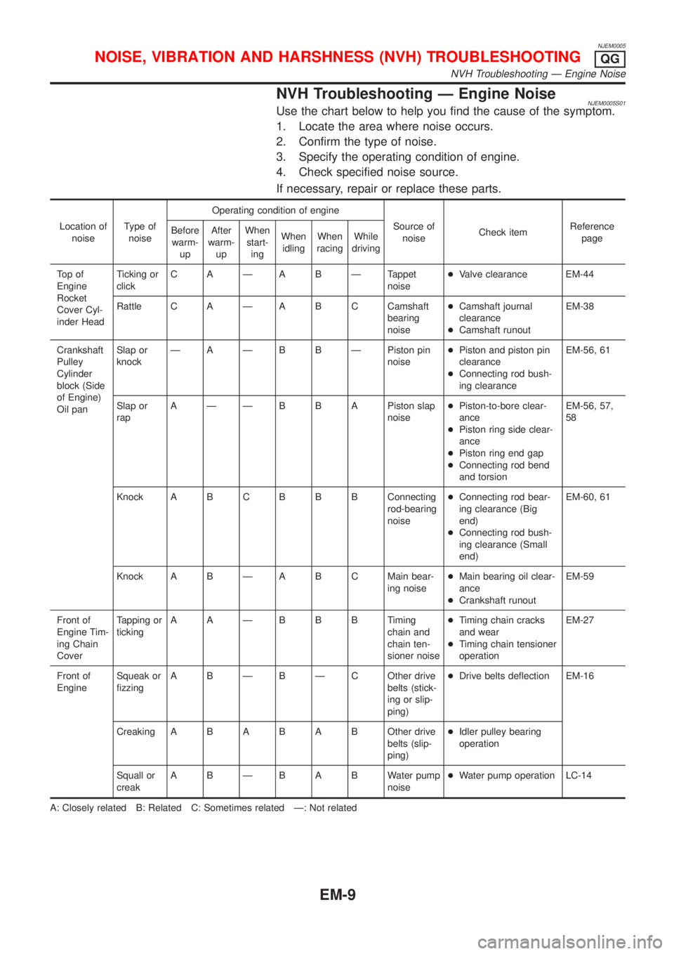
NVH Troubleshooting Ð Engine NoiseNJEM0005S01Use the chart below to help you find the cause of the symptom.
1. Locate the area where noise occurs.
2. Confirm the type of noise.
3. Specify the operating condition of engine.
4. Check specified noise source.
If necessary, repair or replace these parts.
Location of
noiseType of
noiseOperating condition of engine
Source of
noiseCheck itemReference
page Before
warm-
upAfter
warm-
upWhen
start-
ingWhen
idlingWhen
racingWhile
driving
To p o f
Engine
Rocket
Cover Cyl-
inder HeadTicking or
clickC A Ð A B Ð Tappet
noise+Valve clearance EM-44
Rattle C A Ð A B C Camshaft
bearing
noise+Camshaft journal
clearance
+Camshaft runoutEM-38
Crankshaft
Pulley
Cylinder
block (Side
of Engine)
Oil panSlap or
knockÐ A Ð B B Ð Piston pin
noise+Piston and piston pin
clearance
+Connecting rod bush-
ing clearanceEM-56, 61
Slap or
rapA Ð Ð B B A Piston slap
noise+Piston-to-bore clear-
ance
+Piston ring side clear-
ance
+Piston ring end gap
+Connecting rod bend
and torsionEM-56, 57,
58
Knock A B CB B B Connecting
rod-bearing
noise+Connecting rod bear-
ing clearance (Big
end)
+Connecting rod bush-
ing clearance (Small
end)EM-60, 61
Knock A B Ð A B C Main bear-
ing noise+Main bearing oil clear-
ance
+Crankshaft runoutEM-59
Front of
Engine Tim-
ing Chain
CoverTapping or
tickingAAÐBBBTiming
chain and
chain ten-
sioner noise+Timing chain cracks
and wear
+Timing chain tensioner
operationEM-27
Front of
EngineSqueak or
fizzingA B Ð B Ð C Other drive
belts (stick-
ing or slip-
ping)+Drive belts deflection EM-16
CreakingABABABOther drive
belts (slip-
ping)+Idler pulley bearing
operation
Squall or
creakABÐBABWater pump
noise+Water pump operation LC-14
A: Closely related B: Related C: Sometimes related Ð: Not related
NOISE, VIBRATION AND HARSHNESS (NVH) TROUBLESHOOTINGQG
NVH Troubleshooting Ð Engine Noise
EM-9
Page 2145 of 2898
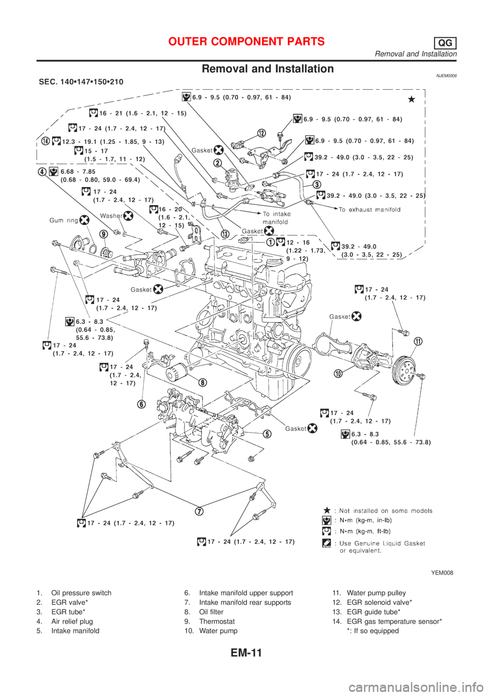
Removal and InstallationNJEM0006
YEM008
1. Oil pressure switch
2. EGR valve*
3. EGR tube*
4. Air relief plug
5. Intake manifold6. Intake manifold upper support
7. Intake manifold rear supports
8. Oil filter
9. Thermostat
10. Water pump11. Water pump pulley
12. EGR solenoid valve*
13. EGR guide tube*
14. EGR gas temperature sensor*
*: If so equipped
OUTER COMPONENT PARTSQG
Removal and Installation
EM-11
Page 2161 of 2898
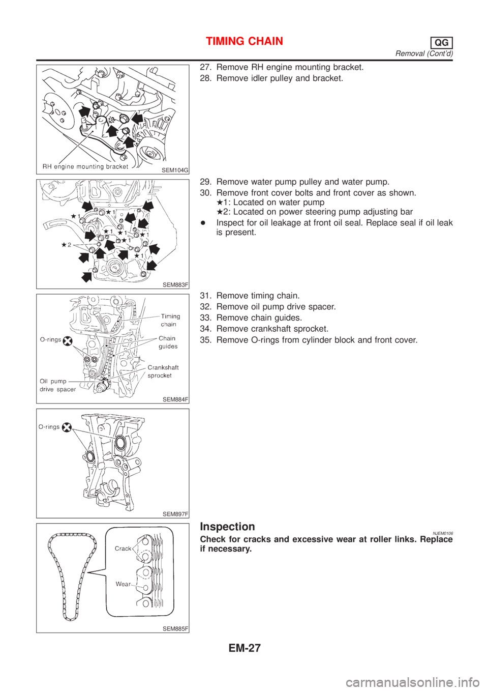
SEM104G
27. Remove RH engine mounting bracket.
28. Remove idler pulley and bracket.
SEM883F
29. Remove water pump pulley and water pump.
30. Remove front cover bolts and front cover as shown.
H1: Located on water pump
H2: Located on power steering pump adjusting bar
+Inspect for oil leakage at front oil seal. Replace seal if oil leak
is present.
SEM884F
SEM897F
31. Remove timing chain.
32. Remove oil pump drive spacer.
33. Remove chain guides.
34. Remove crankshaft sprocket.
35. Remove O-rings from cylinder block and front cover.
SEM885F
InspectionNJEM0106Check for cracks and excessive wear at roller links. Replace
if necessary.
TIMING CHAINQG
Removal (Cont'd)
EM-27
Page 2163 of 2898
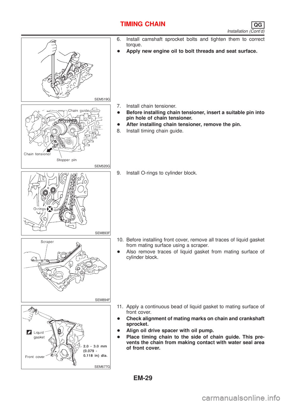
SEM519G
6. Install camshaft sprocket bolts and tighten them to correct
torque.
+Apply new engine oil to bolt threads and seat surface.
SEM520G
7. Install chain tensioner.
+Before installing chain tensioner, insert a suitable pin into
pin hole of chain tensioner.
+After installing chain tensioner, remove the pin.
8. Install timing chain guide.
SEM893F
9. Install O-rings to cylinder block.
SEM894F
10. Before installing front cover, remove all traces of liquid gasket
from mating surface using a scraper.
+Also remove traces of liquid gasket from mating surface of
cylinder block.
SEM677G
11. Apply a continuous bead of liquid gasket to mating surface of
front cover.
+Check alignment of mating marks on chain and crankshaft
sprocket.
+Align oil drive spacer with oil pump.
+Place timing chain to the side of chain guide. This pre-
vents the chain from making contact with water seal area
of front cover.
TIMING CHAINQG
Installation (Cont'd)
EM-29
Page 2164 of 2898
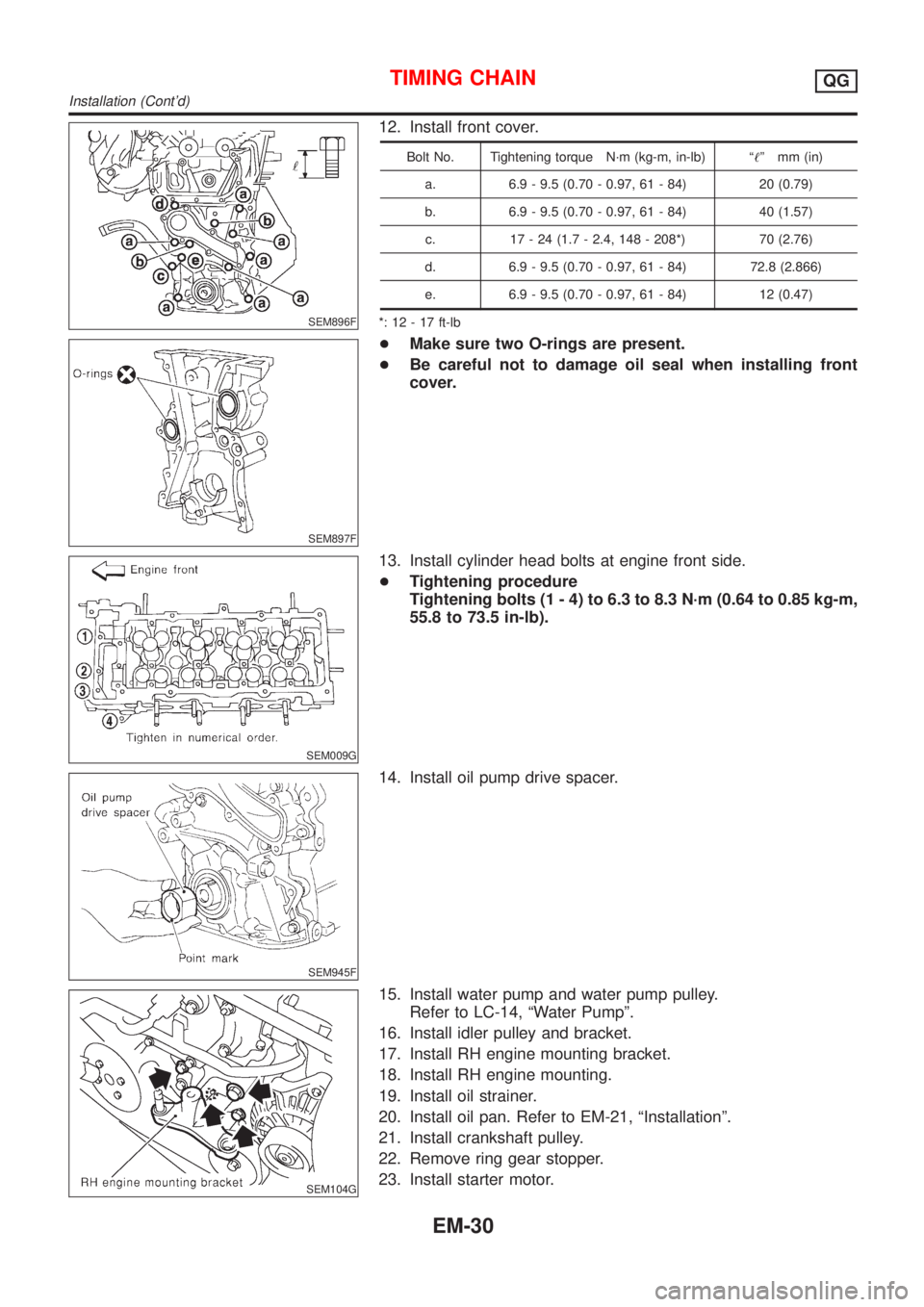
SEM896F
12. Install front cover.
Bolt No. Tightening torque N´m (kg-m, in-lb) ª!º mm (in)
a. 6.9 - 9.5 (0.70 - 0.97, 61 - 84) 20 (0.79)
b. 6.9 - 9.5 (0.70 - 0.97, 61 - 84) 40 (1.57)
c. 17 - 24 (1.7 - 2.4, 148 - 208*) 70 (2.76)
d. 6.9 - 9.5 (0.70 - 0.97, 61 - 84) 72.8 (2.866)
e. 6.9 - 9.5 (0.70 - 0.97, 61 - 84) 12 (0.47)
*: 12 - 17 ft-lb
SEM897F
+Make sure two O-rings are present.
+Be careful not to damage oil seal when installing front
cover.
SEM009G
13. Install cylinder head bolts at engine front side.
+Tightening procedure
Tightening bolts (1 - 4) to 6.3 to 8.3 N´m (0.64 to 0.85 kg-m,
55.8 to 73.5 in-lb).
SEM945F
14. Install oil pump drive spacer.
SEM104G
15. Install water pump and water pump pulley.
Refer to LC-14, ªWater Pumpº.
16. Install idler pulley and bracket.
17. Install RH engine mounting bracket.
18. Install RH engine mounting.
19. Install oil strainer.
20. Install oil pan. Refer to EM-21, ªInstallationº.
21. Install crankshaft pulley.
22. Remove ring gear stopper.
23. Install starter motor.
TIMING CHAINQG
Installation (Cont'd)
EM-30