2001 NISSAN ALMERA water pump
[x] Cancel search: water pumpPage 2216 of 2898
NJEM0051
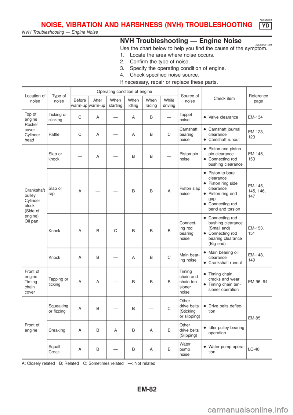
NVH Troubleshooting Ð Engine NoiseNJEM0051S01Use the chart below to help you find the cause of the symptom.
1. Locate the area where noise occurs.
2. Confirm the type of noise.
3. Specify the operating condition of engine.
4. Check specified noise source.
If necessary, repair or replace these parts.
Location of
noiseType of
noiseOperating condition of engine
Source of
noiseCheck itemReference
page Before
warm-upAfter
warm-upWhen
startingWhen
idlingWhen
racingWhile
driving
To p o f
engine
Rocker
cover
Cylinder
headTicking or
clickingC AÐA BÐTappet
noise+Valve clearance EM-134
Rattle C A Ð A B CCamshaft
bearing
noise+Camshaft journal
clearance
+Camshaft runoutEM-123,
123
Crankshaft
pulley
Cylinder
block
(Side of
engine)
Oil panSlap or
knockÐAÐB BÐPiston pin
noise+Piston and piston
pin clearance
+Connecting rod
bushing clearanceEM-145,
153
Slap or
rapAÐÐB B APiston slap
noise+Piston-to-bore
clearance
+Piston ring side
clearance
+Piston ring end
gap
+Connecting rod
bend and torsionEM-145,
145, 146,
147
Knock A B C B B BConnect-
ing rod
bearing
noise+Connecting rod
bushing clearance
(Small end)
+Connecting rod
bearing clearance
(Big end)EM-153,
151
Knock A B Ð A B CMain bear-
ing noise+Main bearing oil
clearance
+Crankshaft runoutEM-148,
149
Front of
engine
Timing
chain
coverTapping or
tickingAAÐBBBTiming
chain and
chain ten-
sioner
noise+Timing chain
cracks and wear
+Timing chain ten-
sioner operationEM-96, 94
Front of
engineSqueaking
or fizzingA BÐBÐCOther
drive belts
(Sticking
or slipping)+Drive belts deflec-
tion
EM-85
CreakingABABABOther
drive belts
(Slipping)+Idler pulley bearing
operation
Squall
CreakABÐBABWater
pump
noise+Water pump opera-
tionLC-40
A: Closely related B: Related C: Sometimes related Ð: Not related
NOISE, VIBRATION AND HARSHNESS (NVH) TROUBLESHOOTINGYD
NVH Troubleshooting Ð Engine Noise
EM-82
Page 2219 of 2898
JEM249G
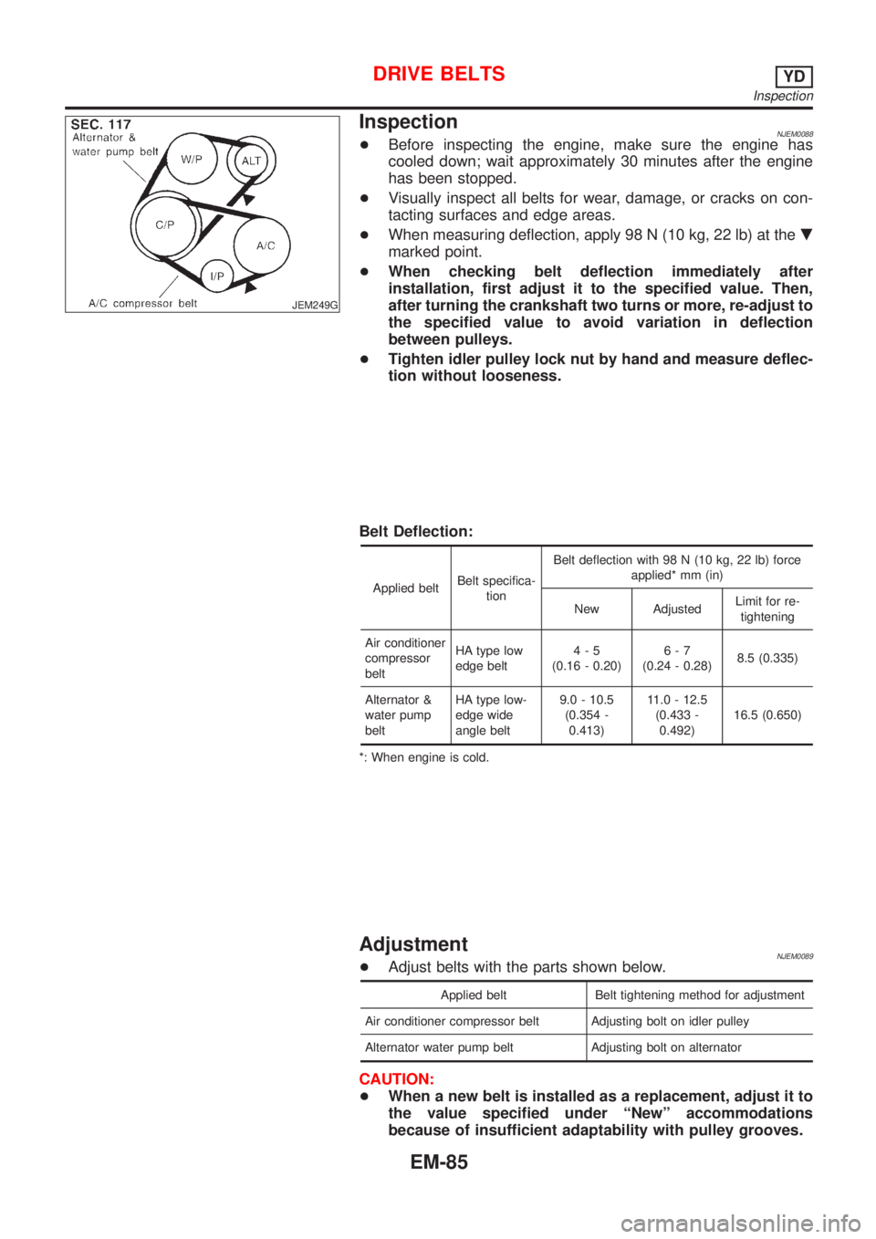
InspectionNJEM0088+Before inspecting the engine, make sure the engine has
cooled down; wait approximately 30 minutes after the engine
has been stopped.
+Visually inspect all belts for wear, damage, or cracks on con-
tacting surfaces and edge areas.
+When measuring deflection, apply 98 N (10 kg, 22 lb) at the.
marked point.
+When checking belt deflection immediately after
installation, first adjust it to the specified value. Then,
after turning the crankshaft two turns or more, re-adjust to
the specified value to avoid variation in deflection
between pulleys.
+Tighten idler pulley lock nut by hand and measure deflec-
tion without looseness.
Belt Deflection:
Applied beltBelt specifica-
tionBelt deflection with 98 N (10 kg, 22 lb) force
applied* mm (in)
New AdjustedLimit for re-
tightening
Air conditioner
compressor
beltHA type low
edge belt4-5
(0.16 - 0.20)6-7
(0.24 - 0.28)8.5 (0.335)
Alternator &
water pump
beltHA type low-
edge wide
angle belt9.0 - 10.5
(0.354 -
0.413)11.0 - 12.5
(0.433 -
0.492)16.5 (0.650)
*: When engine is cold.
AdjustmentNJEM0089+Adjust belts with the parts shown below.
Applied belt Belt tightening method for adjustment
Air conditioner compressor belt Adjusting bolt on idler pulley
Alternator water pump belt Adjusting bolt on alternator
CAUTION:
+When a new belt is installed as a replacement, adjust it to
the value specified under ªNewº accommodations
because of insufficient adaptability with pulley grooves.
DRIVE BELTSYD
Inspection
EM-85
Page 2220 of 2898
+If the belt deflection of the current belt is out of the ªLimit
for re-tighteningº, adjust to the ªAdjusted valueº.
+When checking belt deflection immediately after
installation, first adjust it to the specified value. Then,
after turning crankshaft two turns or more, re-adjust it to
the specified value to avoid variation in deflection
between pulleys.
+Make sure the belts are fully fitted into the pulley grooves
during installation.
+Handle with care to avoid smearing the belts with oil or
cooling water etc.
+Do not twist or bend the belts with strong force.
JEM251G
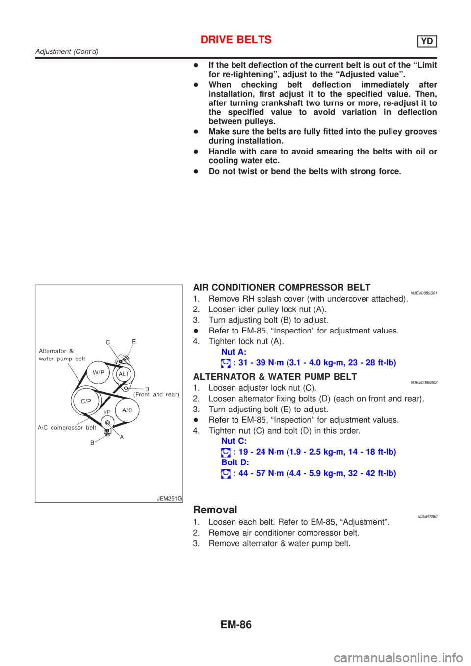
AIR CONDITIONER COMPRESSOR BELTNJEM0089S011. Remove RH splash cover (with undercover attached).
2. Loosen idler pulley lock nut (A).
3. Turn adjusting bolt (B) to adjust.
+Refer to EM-85, ªInspectionº for adjustment values.
4. Tighten lock nut (A).
Nut A:
: 31 - 39 N´m (3.1 - 4.0 kg-m, 23 - 28 ft-lb)
ALTERNATOR & WATER PUMP BELTNJEM0089S021. Loosen adjuster lock nut (C).
2. Loosen alternator fixing bolts (D) (each on front and rear).
3. Turn adjusting bolt (E) to adjust.
+Refer to EM-85, ªInspectionº for adjustment values.
4. Tighten nut (C) and bolt (D) in this order.
Nut C:
: 19 - 24 N´m (1.9 - 2.5 kg-m, 14 - 18 ft-lb)
Bolt D:
: 44 - 57 N´m (4.4 - 5.9 kg-m, 32 - 42 ft-lb)
RemovalNJEM00901. Loosen each belt. Refer to EM-85, ªAdjustmentº.
2. Remove air conditioner compressor belt.
3. Remove alternator & water pump belt.
DRIVE BELTSYD
Adjustment (Cont'd)
EM-86
Page 2242 of 2898
JEM238G
FUEL PIPINGNJEM0109S02RemovalNJEM0109S0201+To prevent fuel from flowing out, plug the opening of the hose
with a blind plug after disconnection.
+Be careful not to spill fuel in the engine compartment.
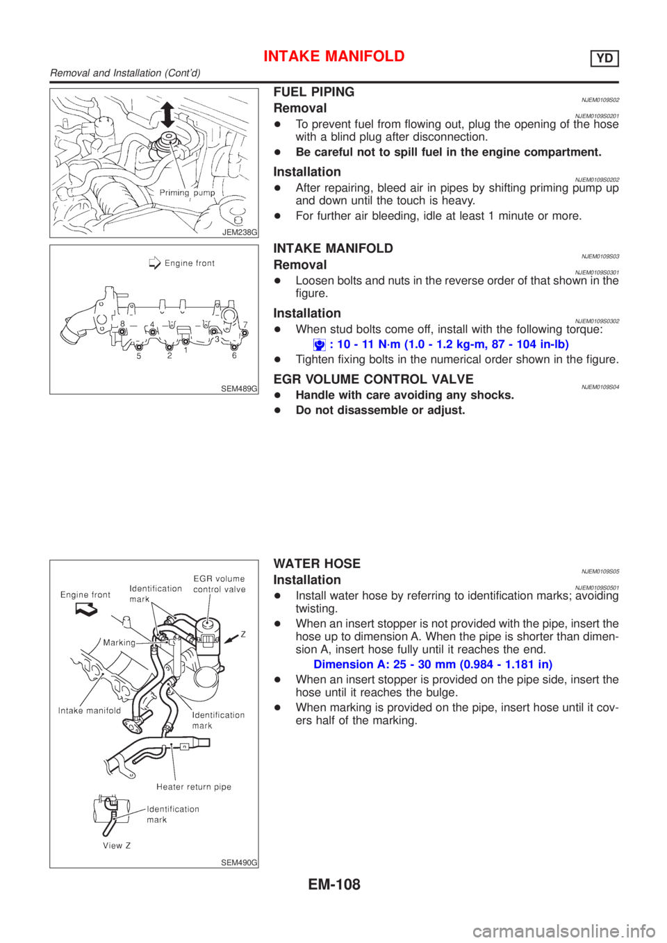
InstallationNJEM0109S0202+After repairing, bleed air in pipes by shifting priming pump up
and down until the touch is heavy.
+For further air bleeding, idle at least 1 minute or more.
SEM489G
INTAKE MANIFOLDNJEM0109S03RemovalNJEM0109S0301+Loosen bolts and nuts in the reverse order of that shown in the
figure.
InstallationNJEM0109S0302+When stud bolts come off, install with the following torque:
: 10 - 11 N´m (1.0 - 1.2 kg-m, 87 - 104 in-lb)
+Tighten fixing bolts in the numerical order shown in the figure.
EGR VOLUME CONTROL VALVENJEM0109S04+Handle with care avoiding any shocks.
+Do not disassemble or adjust.
SEM490G
WATER HOSENJEM0109S05InstallationNJEM0109S0501+Install water hose by referring to identification marks; avoiding
twisting.
+When an insert stopper is not provided with the pipe, insert the
hose up to dimension A. When the pipe is shorter than dimen-
sion A, insert hose fully until it reaches the end.
Dimension A: 25 - 30 mm (0.984 - 1.181 in)
+When an insert stopper is provided on the pipe side, insert the
hose until it reaches the bulge.
+When marking is provided on the pipe, insert hose until it cov-
ers half of the marking.
INTAKE MANIFOLDYD
Removal and Installation (Cont'd)
EM-108
Page 2276 of 2898
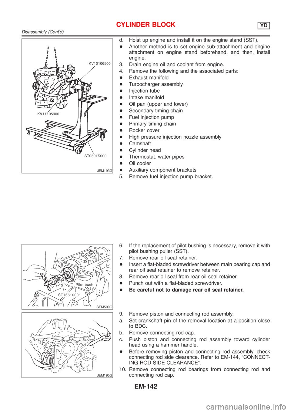
JEM193G
d. Hoist up engine and install it on the engine stand (SST).
+Another method is to set engine sub-attachment and engine
attachment on engine stand beforehand, and then, install
engine.
3. Drain engine oil and coolant from engine.
4. Remove the following and the associated parts:
+Exhaust manifold
+Turbocharger assembly
+Injection tube
+Intake manifold
+Oil pan (upper and lower)
+Secondary timing chain
+Fuel injection pump
+Primary timing chain
+Rocker cover
+High pressure injection nozzle assembly
+Camshaft
+Cylinder head
+Thermostat, water pipes
+Oil cooler
+Auxiliary component brackets
5. Remove fuel injection pump bracket.
SEM500G
6. If the replacement of pilot bushing is necessary, remove it with
pilot bushing puller (SST).
7. Remove rear oil seal retainer.
+Insert a flat-bladed screwdriver between main bearing cap and
rear oil seal retainer to remove retainer.
8. Remove rear oil seal from rear oil seal retainer.
+Punch out with a flat-bladed screwdriver.
+Be careful not to damage rear oil seal retainer.
JEM195G
9. Remove piston and connecting rod assembly.
a. Set crankshaft pin of the removal location at a position close
to BDC.
b. Remove connecting rod cap.
c. Push piston and connecting rod assembly toward cylinder
head using a hammer handle.
+Before removing piston and connecting rod assembly, check
connecting rod side clearance. Refer to EM-144, ªCONNECT-
ING ROD SIDE CLEARANCEº.
10. Remove connecting rod bearings from connecting rod and
connecting rod cap.
CYLINDER BLOCKYD
Disassembly (Cont'd)
EM-142
Page 2294 of 2898
General SpecificationsNJEM0075
Cylinder arrangementIn-line 4
Displacement cm
3(cu in)2,184 (133.27)
Bore and stroke mm (in)86 x 94 (3.39 x 3.70)
Valve arrangementDOHC
Firing order1-3-4-2
Number of piston ringsCompression 2
Oil 1
Number of main bearings5
Compression ratio18.0
Compression PressureNJEM0076Unit: kPa (bar, kg/cm2, psi)/200 rpm
Compression pressureStandard 3,138 (31.4, 32.0, 455)
Minimum 2,452 (24.5, 25.0, 356)
Differential limit between cylinders 490 (4.9, 5.0, 71)
Belt DeflectionNJEM0111
Applied belt Belt specificationBelt deflection with 98 N (10 kg, 22 lb) force applied*
mm (in)
New AdjustedLimit for re-tighten-
ing
Air conditioner compressor belt HA type low edge belt4-5
(0.16 - 0.20)6-7
(0.24 - 0.28)8.5 (0.335)
Alternator & water pump beltHA type low-edge wide angle
belt9.0 - 10.5
(0.354 - 0.413)11.0 - 12.5
(0.433 - 0.492)16.5 (0.650)
*: When engine is cold.
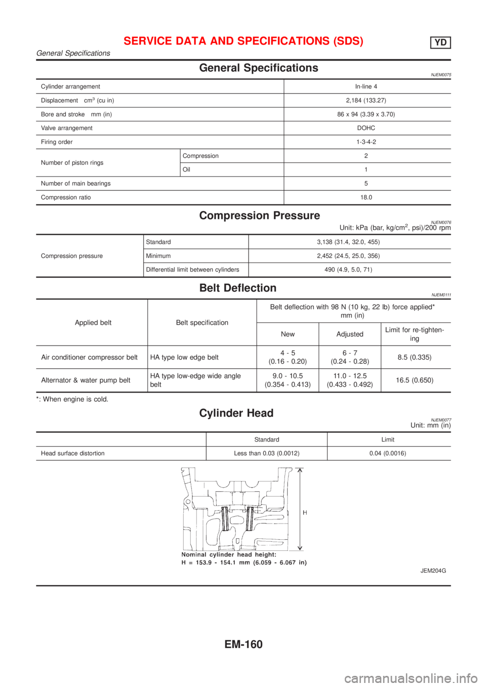
Cylinder HeadNJEM0077Unit: mm (in)
Standard Limit
Head surface distortion Less than 0.03 (0.0012) 0.04 (0.0016)
JEM204G
SERVICE DATA AND SPECIFICATIONS (SDS)YD
General Specifications
EM-160
Page 2305 of 2898
ACCELERATOR CONTROL, FUEL &
EXHAUST SYSTEMS
SECTION
FE
CONTENTS
QG
PREPARATION...............................................................2
Special Service Tools ..................................................2
Commercial Service Tools ...........................................2
ACCELERATOR CONTROL SYSTEM...........................3
Removal and Installation .............................................3
Adjusting Accelerator Wire ..........................................3
MODELS WITH THROTTLE OPENER.........................3
MODELS WITHOUT THROTTLE OPENER..................4
FUEL SYSTEM................................................................5
Checking Fuel Lines ....................................................5
Removal and Installation .............................................5
Fuel Tank .....................................................................6
REMOVAL.................................................................7
INSTALLATION........................................................ 11
Fuel Pump, Fuel Level Sensor Unit and Fuel
Filter ...........................................................................12
REMOVAL...............................................................12
INSTALLATION........................................................14
EXHAUST SYSTEM......................................................15
Checking Exhaust System.........................................15
Removal and Installation ...........................................15
YD
PREPARATION.............................................................18
Special Service Tool ..................................................18Commercial Service Tool ...........................................18
ACCELERATOR CONTROL SYSTEM.........................19
Removal and Installation ...........................................19
Inspection...................................................................19
FUEL SYSTEM..............................................................20
Checking Fuel Lines ..................................................20
Water Draining from Fuel Filter .................................20
DRAINING WATER..................................................20
FUEL FILTER CHECK..............................................20
Changing Fuel Filter ..................................................20
REMOVAL...............................................................20
INSTALLATION........................................................21
Bleeding Fuel Filter....................................................21
Checking Priming Pump ............................................21
Checking Water in Fuel Filter Sensor (where
fitted) ..........................................................................22
Removal and Installation ...........................................22
Fuel Tank ...................................................................23
REMOVAL...............................................................25
INSTALLATION........................................................28
Fuel Level Sensor Unit ..............................................29
REMOVAL...............................................................30
INSTALLATION........................................................31
EXHAUST SYSTEM......................................................32
Checking Exhaust System.........................................32
Removal and Installation ...........................................32
Page 2506 of 2898

Water pump ......................................... LC-14, 39
Water temperature gauge ........................ EL-144
Weatherstrip - See Exterior ....................... BT-47
Wheel alignment (rear) ............................. SU-18
Wheel bearing (front) .................................. AX-3
Wheel bearing (rear) ................................. AX-23
Wheel hub (front) ........................................ AX-5
Wheel hub (rear) ....................................... AX-24
Wheel sensors (ABS) ............................... BR-97
Wheelarch height ........................................ SU-6
Wheelbase (Dimensions) ........................... GI-43
Wide open & closed throttle positionswitch ................................................... EC-207
Width (Dimensions) .................................... GI-43
Window, rear .............................................. BT-71
Windshield ................................................. BT-71
Wiper, front .............................................. EL-215
Wiring diagram (cell code) list ................. EL-575
Wiring diagrams .......................................... GI-11
Withdrawal lever (clutch) ..................... CL-17, 20
Wrist pin -
See Piston pin inspection ............. EM-56, 145
ALPHABETICAL INDEX
IDX-8