2001 NISSAN ALMERA coolant
[x] Cancel search: coolantPage 1227 of 2898
DescriptionNJEC1752SYSTEM DESCRIPTIONNJEC1752S01
Sensor Input Signal to ECMECM func-
tionActuator
Crankshaft position sensor (POS) Engine speed
EVAP can-
ister purge
controlEVAP canister purge volume
control solenoid valve Camshaft position sensor (PHASE) Engine speed and cylinder number
Mass air flow sensor Amount of intake air
Engine coolant temperature sensor Engine coolant temperature
Battery Battery voltage
Ignition switch Start signal
Closed throttle position switch (If so
equipped)Closed throttle position
Throttle position sensor Throttle position
Heated oxygen sensor 1 (front)Density of oxygen in exhaust gas
(Mixture ratio feedback signal)
Vehicle speed sensor Vehicle speed
This system controls flow rate of fuel vapor from the EVAP canis-
ter. The opening of the vapor by-pass passage in the EVAP canis-
ter purge volume control solenoid valve changes to control the flow
rate. The EVAP canister purge volume control solenoid valve
repeats ON/OFF operation according to the signal sent from the
ECM. The opening of the valve varies for optimum engine control.
The optimum value stored in the ECM is determined by consider-
ing various engine conditions. When the engine is operating, the
flow rate of fuel vapor from the EVAP canister is regulated as the
air flow changes.
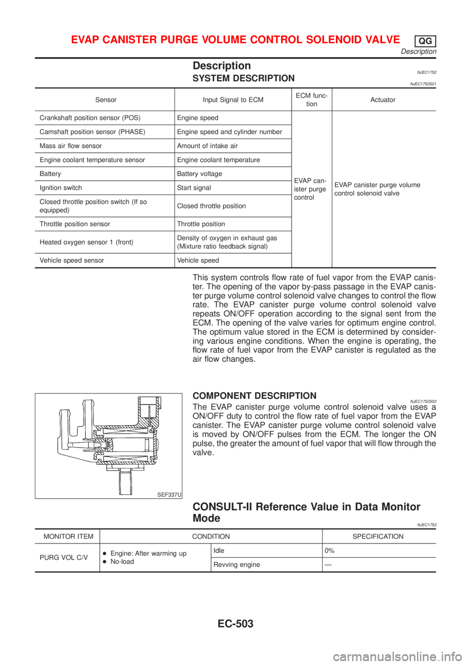
SEF337U
COMPONENT DESCRIPTIONNJEC1752S02The EVAP canister purge volume control solenoid valve uses a
ON/OFF duty to control the flow rate of fuel vapor from the EVAP
canister. The EVAP canister purge volume control solenoid valve
is moved by ON/OFF pulses from the ECM. The longer the ON
pulse, the greater the amount of fuel vapor that will flow through the
valve.
CONSULT-II Reference Value in Data Monitor
Mode
NJEC1753
MONITOR ITEM CONDITION SPECIFICATION
PURG VOL C/V+Engine: After warming up
+No-loadIdle 0%
Revving engine Ð
EVAP CANISTER PURGE VOLUME CONTROL SOLENOID VALVEQG
Description
EC-503
Page 1235 of 2898
DescriptionNJEC1758SYSTEM DESCRIPTIONNJEC1758S01
Sensor Input Signal to ECMECM func-
tionActuator
Crankshaft position sensor (POS) Engine speed
Idle air
controlIACV-AAC valve Camshaft position sensor (PHASE) Engine speed and cylinder number
Engine coolant temperature sensor Engine coolant temperature
Ignition switch Start signal
Throttle position sensor Throttle position
PNP switch Park/Neutral position
Air conditioner switch Air conditioner operation
Power steering oil pressure switch Power steering load signal
Battery Battery voltage
Vehicle speed sensor Vehicle speed
Cooling fan Cooling fan operation
Electrical load Electrical load signal
This system automatically controls engine idle speed to a specified
level. Idle speed is controlled through fine adjustment of the
amount of air which by-passes the throttle valve via IACV-AAC
valve. The IACV-AAC valve changes the opening of the air by-pass
passage to control the amount of auxiliary air. This valve is actu-
ated by a step motor built into the valve, which moves the valve in
the axial direction in steps corresponding to the ECM output sig-
nals. One step of IACV-AAC valve movement causes the respec-
tive opening of the air by-pass passage. (i.e. when the step
advances, the opening is enlarged.) The opening of the valve is
varied to allow for optimum control of the engine idling speed. The
crankshaft position sensor (POS) detects the actual engine speed
and sends a signal to the ECM. The ECM then controls the step
position of the IACV-AAC valve so that engine speed coincides with
the target value memorized in ECM. The target engine speed is the
lowest speed at which the engine can operate steadily. The opti-
mum value stored in the ECM is determined by taking into consid-
eration various engine conditions, such as during warm up,
deceleration, and engine load (air conditioner, power steering, cool-
ing fan operation and electrical load).
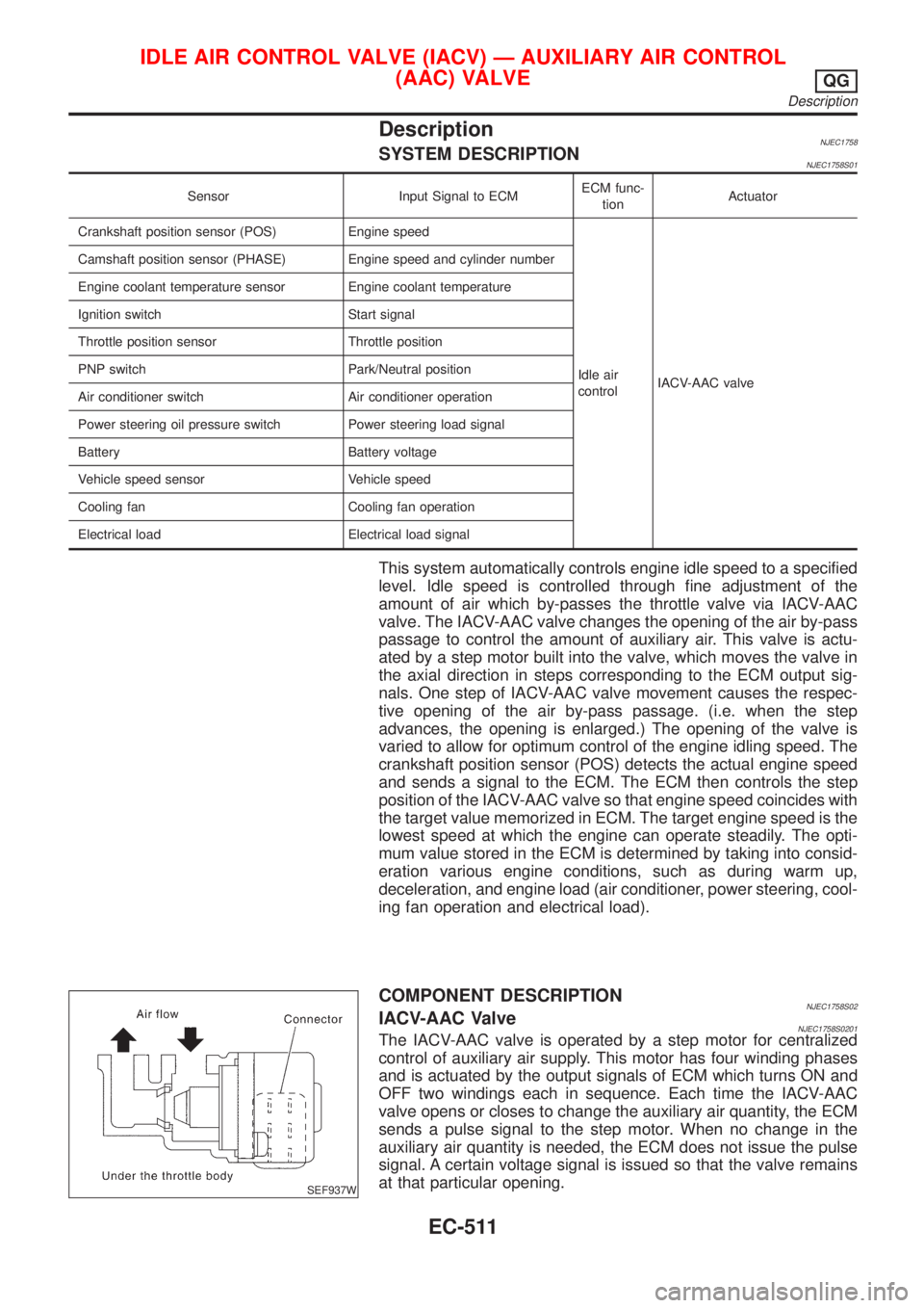
SEF937W
COMPONENT DESCRIPTIONNJEC1758S02IACV-AAC ValveNJEC1758S0201The IACV-AAC valve is operated by a step motor for centralized
control of auxiliary air supply. This motor has four winding phases
and is actuated by the output signals of ECM which turns ON and
OFF two windings each in sequence. Each time the IACV-AAC
valve opens or closes to change the auxiliary air quantity, the ECM
sends a pulse signal to the step motor. When no change in the
auxiliary air quantity is needed, the ECM does not issue the pulse
signal. A certain voltage signal is issued so that the valve remains
at that particular opening.
IDLE AIR CONTROL VALVE (IACV) Ð AUXILIARY AIR CONTROL
(AAC) VALVE
QG
Description
EC-511
Page 1250 of 2898
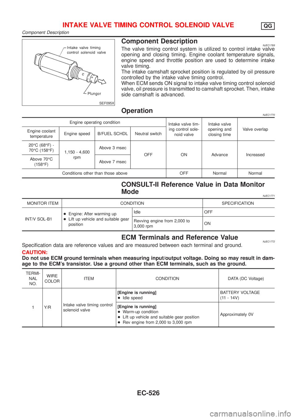
SEF095X
Component DescriptionNJEC1769The valve timing control system is utilized to control intake valve
opening and closing timing. Engine coolant temperature signals,
engine speed and throttle position are used to determine intake
valve timing.
The intake camshaft sprocket position is regulated by oil pressure
controlled by the intake valve timing control.
When ECM sends ON signal to intake valve timing control solenoid
valve, oil pressure is transmitted to camshaft sprocket. Then, intake
side camshaft is advanced.
OperationNJEC1770
Engine operating condition
Intake valve tim-
ing control sole-
noid valveIntake valve
opening and
closing timeValve overlap
Engine coolant
temperatureEngine speed B/FUEL SCHDL Neutral switch
20ÉC (68ÉF) -
70ÉC (158ÉF)
1,150 - 4,600
rpmAbove 3 msec
OFF ON Advance Increased
Above 70ÉC
(158ÉF)Above 7 msec
Conditions other than those above OFF Normal Normal
CONSULT-II Reference Value in Data Monitor
Mode
NJEC1771
MONITOR ITEM CONDITION SPECIFICATION
INT/V SOL-B1+Engine: After warming up
+Lift up vehicle and suitable gear
positionIdle OFF
Revving engine from 2,000 to
3,000 rpmON
ECM Terminals and Reference ValueNJEC1772Specification data are reference values and are measured between each terminal and ground.
CAUTION:
Do not use ECM ground terminals when measuring input/output voltage. Doing so may result in dam-
age to the ECM's transistor. Use a ground other than ECM terminals, such as the ground.
TERMI-
NAL
NO.WIRE
COLORITEM CONDITION DATA (DC Voltage)
1 Y/RIntake valve timing control
solenoid valve[Engine is running]
+Idle speedBATTERY VOLTAGE
(11 - 14V)
[Engine is running]
+Warm-up condition
+Lift up vehicle and suitable gear position
+Rev engine from 2,000 to 3,000 rpmApproximately 0V
INTAKE VALVE TIMING CONTROL SOLENOID VALVEQG
Component Description
EC-526
Page 1317 of 2898
Fuel Pressure RegulatorNJEC0467
Fuel pressure at idling
kPa (bar, kg/cm2, psi)Vacuum hose is connected Approximately 235 (2.35, 2.4, 34)
Vacuum hose is disconnected Approximately 294 (2.94, 3.0, 43)
Idle Speed and Ignition TimingNJEC0468
Target idle speed* rpmM/T: 700±50
A/T: 800±50
Air conditioner: ON rpm825 or more
Ignition timingM/T: 8±5É BTDC
A/T: 10±5É BTDC
Throttle position sensor idle position V 0.15 - 0.85
*: Under the following conditions:
+Air conditioner switch: OFF
+Electrical load: OFF (Lights, heater fan & rear window defogger)
+Steering wheel: Kept in straight-ahead position
Mass Air Flow SensorNJEC0470
Supply voltage (Heater) VBattery voltage (11 - 14)
Supply voltage (Sensor) VApproximately 5
Output voltage V1.0 - 1.7*
Mass air flow
(Using CONSULT-II or GST) g´m/sec1.0 - 4.0 at idle*
5.0 - 10.0 at 2,500 rpm*
*: Engine is warmed up to normal operating temperature and idling under no-load.
Intake Air Temperature SensorNJEC0480
Temperature ÉC (ÉF) Resistance kW
20 (68) 2.1 - 2.9
80 (176) 0.27 - 0.38
Engine Coolant Temperature SensorNJEC0471
Temperature ÉC (ÉF) Resistance kW
20 (68) 2.1 - 2.9
50 (122) 0.68 - 1.00
90 (194) 0.236 - 0.260
Throttle Position SensorNJEC0477
Throttle valve conditions Voltage (V)
Completely closed0.15 - 0.85
Completely open3.5 - 4.7
Heated Oxygen Sensor 1 Heater (Front)NJEC0478
Resistance [at 25ÉC (77ÉF)]W2.3 - 4.3
Heated Oxygen Sensor 2 Heater (Rear)NJEC0483
Resistance [at 25ÉC (77ÉF)]W2.3 - 4.3
SERVICE DATA AND SPECIFICATIONS (SDS)QG
Fuel Pressure Regulator
EC-593
Page 1320 of 2898
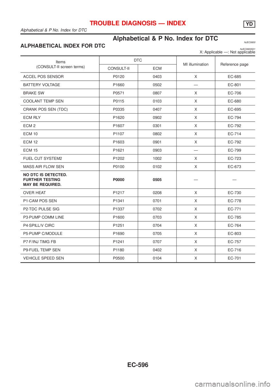
Alphabetical & P No. Index for DTCNJEC0600ALPHABETICAL INDEX FOR DTCNJEC0600S01X: Applicable Ð: Not applicable
Items
(CONSULT-II screen terms)DTC
MI illumination Reference page
CONSULT-II ECM
ACCEL POS SENSOR P0120 0403 X EC-685
BATTERY VOLTAGE P1660 0502 Ð EC-801
BRAKE SW P0571 0807 X EC-706
COOLANT TEMP SEN P0115 0103 X EC-680
CRANK POS SEN (TDC) P0335 0407 X EC-695
ECM RLY P1620 0902 X EC-794
ECM 2 P1607 0301 X EC-792
ECM 10 P1107 0802 X EC-714
ECM 12 P1603 0901 X EC-792
ECM 15 P1621 0903 Ð EC-799
FUEL CUT SYSTEM2 P1202 1002 X EC-723
MASS AIR FLOW SEN P0100 0102 X EC-673
NO DTC IS DETECTED.
FURTHER TESTING
MAY BE REQUIRED.P0000 0505ÐÐ
OVER HEAT P1217 0208 X EC-730
P1´CAM POS SEN P1341 0701 X EC-778
P2´TDC PULSE SIG P1337 0702 X EC-771
P3´PUMP COMM LINE P1600 0703 X EC-785
P4´SPILL/V CIRC P1251 0704 X EC-764
P5´PUMP C/MODULE P1690 0705 X EC-803
P7´F/INJ TIMG FB P1241 0707 X EC-757
P9´FUEL TEMP SEN P1180 0402 X EC-716
VEHICLE SPEED SEN P0500 0104 X EC-701
TROUBLE DIAGNOSIS Ð INDEXYD
Alphabetical & P No. Index for DTC
EC-596
Page 1321 of 2898
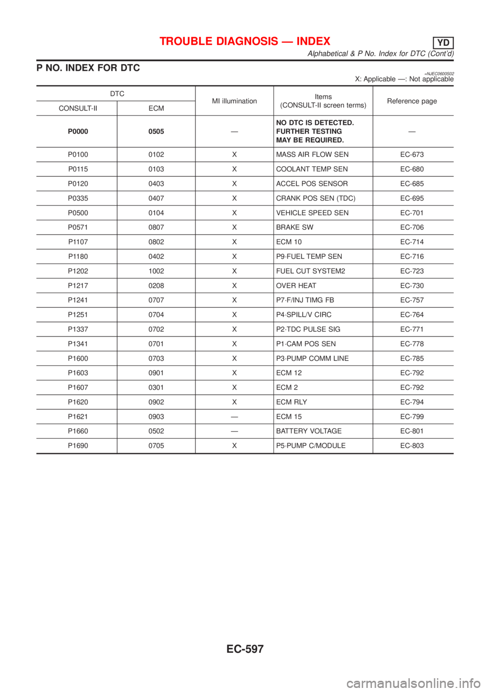
P NO. INDEX FOR DTC=NJEC0600S02X: Applicable Ð: Not applicable
DTC
MI illuminationItems
(CONSULT-II screen terms)Reference page
CONSULT-II ECM
P0000 0505ÐNO DTC IS DETECTED.
FURTHER TESTING
MAY BE REQUIRED.Ð
P0100 0102 X MASS AIR FLOW SEN EC-673
P0115 0103 X COOLANT TEMP SEN EC-680
P0120 0403 X ACCEL POS SENSOR EC-685
P0335 0407 X CRANK POS SEN (TDC) EC-695
P0500 0104 X VEHICLE SPEED SEN EC-701
P0571 0807 X BRAKE SW EC-706
P1107 0802 X ECM 10 EC-714
P1180 0402 X P9´FUEL TEMP SEN EC-716
P1202 1002 X FUEL CUT SYSTEM2 EC-723
P1217 0208 X OVER HEAT EC-730
P1241 0707 X P7´F/INJ TIMG FB EC-757
P1251 0704 X P4´SPILL/V CIRC EC-764
P1337 0702 X P2´TDC PULSE SIG EC-771
P1341 0701 X P1´CAM POS SEN EC-778
P1600 0703 X P3´PUMP COMM LINE EC-785
P1603 0901 X ECM 12 EC-792
P1607 0301 X ECM 2 EC-792
P1620 0902 X ECM RLY EC-794
P1621 0903 Ð ECM 15 EC-799
P1660 0502 Ð BATTERY VOLTAGE EC-801
P1690 0705 X P5´PUMP C/MODULE EC-803
TROUBLE DIAGNOSIS Ð INDEXYD
Alphabetical & P No. Index for DTC (Cont'd)
EC-597
Page 1333 of 2898
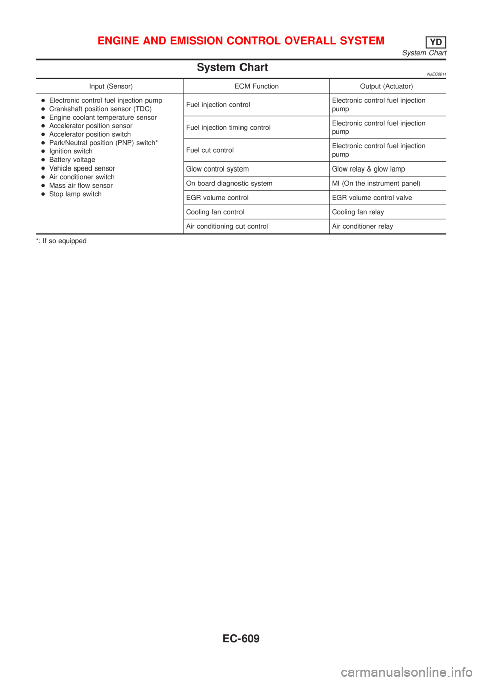
System ChartNJEC0611
Input (Sensor) ECM Function Output (Actuator)
+Electronic control fuel injection pump
+Crankshaft position sensor (TDC)
+Engine coolant temperature sensor
+Accelerator position sensor
+Accelerator position switch
+Park/Neutral position (PNP) switch*
+Ignition switch
+Battery voltage
+Vehicle speed sensor
+Air conditioner switch
+Mass air flow sensor
+Stop lamp switchFuel injection controlElectronic control fuel injection
pump
Fuel injection timing controlElectronic control fuel injection
pump
Fuel cut controlElectronic control fuel injection
pump
Glow control system Glow relay & glow lamp
On board diagnostic system MI (On the instrument panel)
EGR volume control EGR volume control valve
Cooling fan control Cooling fan relay
Air conditioning cut control Air conditioner relay
*: If so equipped
ENGINE AND EMISSION CONTROL OVERALL SYSTEMYD
System Chart
EC-609
Page 1334 of 2898
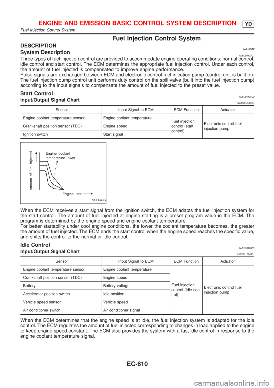
Fuel Injection Control System
DESCRIPTIONNJEC0612System DescriptionNJEC0612S01Three types of fuel injection control are provided to accommodate engine operating conditions; normal control,
idle control and start control. The ECM determines the appropriate fuel injection control. Under each control,
the amount of fuel injected is compensated to improve engine performance.
Pulse signals are exchanged between ECM and electronic control fuel injection pump (control unit is built-in).
The fuel injection pump control unit performs duty control on the spill valve (built into the fuel injection pump)
according to the input signals to compensate the amount of fuel injected to the preset value.
Start ControlNJEC0612S02Input/Output Signal ChartNJEC0612S0201
Sensor Input Signal to ECM ECM Function Actuator
Engine coolant temperature sensor Engine coolant temperature
Fuel injection
control (start
control)Electronic control fuel
injection pump Crankshaft position sensor (TDC) Engine speed
Ignition switch Start signal
SEF648S
When the ECM receives a start signal from the ignition switch, the ECM adapts the fuel injection system for
the start control. The amount of fuel injected at engine starting is a preset program value in the ECM. The
program is determined by the engine speed and engine coolant temperature.
For better startability under cool engine conditions, the lower the coolant temperature becomes, the greater
the amount of fuel injected. The ECM ends the start control when the engine speed reaches the specific value,
and shifts the control to the normal or idle control.
Idle ControlNJEC0612S03Input/Output Signal ChartNJEC0612S0301
Sensor Input Signal to ECM ECM Function Actuator
Engine coolant temperature sensor Engine coolant temperature
Fuel injection
control (Idle con-
trol)Electronic control fuel
injection pump Crankshaft position sensor (TDC) Engine speed
Battery Battery voltage
Accelerator position switch Idle position
Vehicle speed sensor Vehicle speed
Air conditioner switch Air conditioner signal
When the ECM determines that the engine speed is at idle, the fuel injection system is adapted for the idle
control. The ECM regulates the amount of fuel injected corresponding to changes in load applied to the engine
to keep engine speed constant. The ECM also provides the system with a fast idle control in response to the
engine coolant temperature signal.
ENGINE AND EMISSION BASIC CONTROL SYSTEM DESCRIPTIONYD
Fuel Injection Control System
EC-610