Page 1377 of 2898
SYSTEM Ð ENGINE CONTROL system
Malfunction
SYMPTOM
Reference page
Feature of symptom, Check pointROUGH IDLE/HUNTING
IDLING VIBRATION
SLOW/NO RETURN TO IDLE
OVERHEAT/HIGH ENGINE COOLANT TEMPERATURE
EXCESSIVE FUEL CONSUMPTION
EXCESSIVE OIL CONSUMPTION
ABNORMAL SMOKE COLOR
DEAD BATTERY (UNDER CHARGE)
Malfunction indicator illuminates.
Can be detected by CONSULT-II?BLACK SMOKE
WHITE SMOKEWarranty symptom code AG AH AJ AK AL AM AP HA
ENGINE CONTROL
Start signal circuit *a, *b EC-823 *3
Accelerator position switch (Idle) circuit*a, *c
EC-685
*b 1 1 *4
Ignition switch circuit*a
EC-666
*b*5
Power supply for ECM circuit*a
1 1 EC-666
*b
1 - 5: The numbers refer to the order of inspection.
(continued on next page)
*a: Open
*b: Short
*c: Ground short
*d: Noise
*3: Start control does not function.
*4: Accelerator position sensor NG signal is output.
*5: Engine does not stop.
TROUBLE DIAGNOSIS Ð GENERAL DESCRIPTIONYD
Symptom Matrix Chart (Cont'd)
EC-653
Page 1379 of 2898

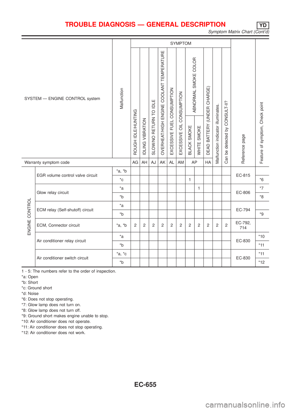
SYSTEM Ð ENGINE CONTROL system
Malfunction
SYMPTOM
Reference page
Feature of symptom, Check pointROUGH IDLE/HUNTING
IDLING VIBRATION
SLOW/NO RETURN TO IDLE
OVERHEAT/HIGH ENGINE COOLANT TEMPERATURE
EXCESSIVE FUEL CONSUMPTION
EXCESSIVE OIL CONSUMPTION
ABNORMAL SMOKE COLOR
DEAD BATTERY (UNDER CHARGE)
Malfunction indicator illuminates.
Can be detected by CONSULT-II?BLACK SMOKE
WHITE SMOKEWarranty symptom code AG AH AJ AK AL AM AP HA
ENGINE CONTROL
EGR volume control valve circuit*a, *b
EC-815
*c 1 *6
Glow relay circuit*a 1
EC-806*7
*b*8
ECM relay (Self-shutoff) circuit*a
EC-794
*b*9
ECM, Connector circuit *a, *b22222222222EC-792,
714
Air conditioner relay circuit*a
EC-830*10
*b*11
Air conditioner switch circuit*a, *c
EC-830*11
*b*12
1 - 5: The numbers refer to the order of inspection.
*a: Open
*b: Short
*c: Ground short
*d: Noise
*6: Does not stop operating.
*7: Glow lamp does not turn on.
*8: Glow lamp does not turn off.
*9: Ground short makes engine unable to stop.
*10: Air conditioner does not operate.
*11: Air conditioner does not stop operating.
*12: Air conditioner does not work.
TROUBLE DIAGNOSIS Ð GENERAL DESCRIPTIONYD
Symptom Matrix Chart (Cont'd)
EC-655
Page 1386 of 2898
![NISSAN ALMERA 2001 Service Manual TERMI-
NAL
NO.WIRE
COLORITEM CONDITIONDATA (DC Voltage and Pulse
Signal)
331 ORCrankshaft position sen-
sor (TDC) ground[Engine is running]
+Warm-up condition
+Idle speedApproximately 0V
334 B/REngine NISSAN ALMERA 2001 Service Manual TERMI-
NAL
NO.WIRE
COLORITEM CONDITIONDATA (DC Voltage and Pulse
Signal)
331 ORCrankshaft position sen-
sor (TDC) ground[Engine is running]
+Warm-up condition
+Idle speedApproximately 0V
334 B/REngine](/manual-img/5/57348/w960_57348-1385.png)
TERMI-
NAL
NO.WIRE
COLORITEM CONDITIONDATA (DC Voltage and Pulse
Signal)
331 ORCrankshaft position sen-
sor (TDC) ground[Engine is running]
+Warm-up condition
+Idle speedApproximately 0V
334 B/REngine coolant tempera-
ture sensor ground[Ignition switch ªONº]Approximately 0V
337
338
350
351W/L
PU/W
GY
OR/BEGR volume control
valve[Engine is running]
+Warm-up condition
+Idle speed0.1 - 14V
(Voltage signals of each ECM
terminals differ according to the
control position of EGR volume
control valve.)
344 WCrankshaft position sen-
sor (TDC)[Engine is running]
+Warm-up condition
+Idle speedApproximately 0V
SEF333Y
[Engine is running]
+Warm-up condition
+Engine speed is 2,000 rpmApproximately 0V
SEF334Y
347 L/BEngine coolant tempera-
ture sensor[Engine is running]Approximately 0 - 4.8V
Output voltage varies with
engine coolant temperature
403 R/L Air conditioner switch[Engine is running]
+Air conditioner switch is ªOFFºBATTERY VOLTAGE
(11 - 14V)
[Engine is running]
+Both air conditioner switch and blower fan
switch are ªONº
(Compressor is operating)Approximately 0.1V
405 R/G Stop lamp switch[Ignition switch ªONº]
+Brake pedal fully releasedApproximately 0V
[Ignition switch ªONº]
+Brake pedal depressedBATTERY VOLTAGE
(11 - 14V)
416 Y/BBrake pedal position
switch[Ignition switch ªONº]
+Brake pedal fully releasedBATTERY VOLTAGE
(11 - 14V)
[Ignition switch ªONº]
+Brake pedal depressedApproximately 0V
TROUBLE DIAGNOSIS Ð GENERAL DESCRIPTIONYD
ECM Terminals and Reference Value (Cont'd)
EC-662
Page 1404 of 2898

SEF594K
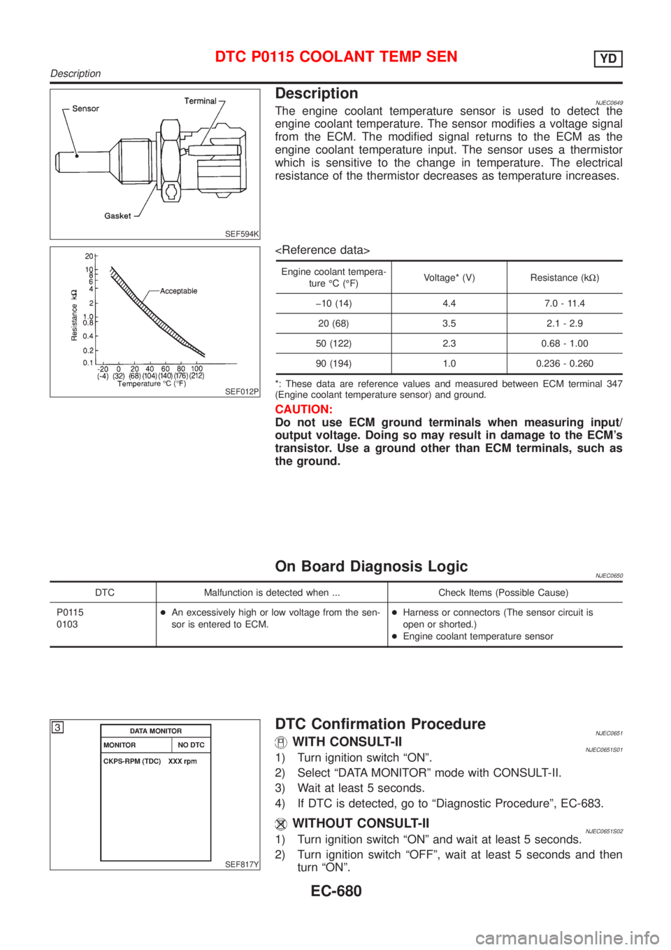
DescriptionNJEC0649The engine coolant temperature sensor is used to detect the
engine coolant temperature. The sensor modifies a voltage signal
from the ECM. The modified signal returns to the ECM as the
engine coolant temperature input. The sensor uses a thermistor
which is sensitive to the change in temperature. The electrical
resistance of the thermistor decreases as temperature increases.
SEF012P
Engine coolant tempera-
ture ÉC (ÉF)Voltage* (V) Resistance (kW)
þ10 (14) 4.4 7.0 - 11.4
20 (68) 3.5 2.1 - 2.9
50 (122) 2.3 0.68 - 1.00
90 (194) 1.0 0.236 - 0.260
*: These data are reference values and measured between ECM terminal 347
(Engine coolant temperature sensor) and ground.
CAUTION:
Do not use ECM ground terminals when measuring input/
output voltage. Doing so may result in damage to the ECM's
transistor. Use a ground other than ECM terminals, such as
the ground.
On Board Diagnosis LogicNJEC0650
DTC Malfunction is detected when ... Check Items (Possible Cause)
P0115
0103+An excessively high or low voltage from the sen-
sor is entered to ECM.+Harness or connectors (The sensor circuit is
open or shorted.)
+Engine coolant temperature sensor
SEF817Y
DTC Confirmation ProcedureNJEC0651WITH CONSULT-IINJEC0651S011) Turn ignition switch ªONº.
2) Select ªDATA MONITORº mode with CONSULT-II.
3) Wait at least 5 seconds.
4) If DTC is detected, go to ªDiagnostic Procedureº, EC-683.
WITHOUT CONSULT-IINJEC0651S021) Turn ignition switch ªONº and wait at least 5 seconds.
2) Turn ignition switch ªOFFº, wait at least 5 seconds and then
turn ªONº.
DTC P0115 COOLANT TEMP SENYD
Description
EC-680
Page 1405 of 2898
3) Perform ªDiagnostic Test Mode II (Self-diagnostic results)º with
ECM.
4) If DTC is detected, go to ªDiagnostic Procedureº, EC-683.
DTC P0115 COOLANT TEMP SENYD
DTC Confirmation Procedure (Cont'd)
EC-681
Page 1406 of 2898
Wiring DiagramNJEC0652
HEC823
DTC P0115 COOLANT TEMP SENYD
Wiring Diagram
EC-682
Page 1407 of 2898
Diagnostic ProcedureNJEC0653
1 CHECK ECTS POWER SUPPLY CIRCUIT
1. Turn ignition switch ªOFFº.
2. Disconnect engine coolant temperature sensor harness connector.
SEF382Y
3. Turn ignition switch ªONº.
4. Check voltage between ECTS terminal 2 and ground with CONSULT-II or tester.
SEF401Y
OK or NG
OK©GO TO 2.
NG©Repair open circuit or short to ground or short to power in harness or connectors.
2 CHECK ECTS GROUND CIRCUIT FOR OPEN AND SHORT
1. Turn ignition switch ªOFFº.
2. Check harness continuity between ECTS terminal 1 and engine ground. Refer to Wiring Diagram.
Continuity should exist.
3. Also check harness for short to ground and short to power.
OK or NG
OK©GO TO 4.
NG©GO TO 3.
3 DETECT MALFUNCTIONING PART
Check the following harness for open or short between ECM and engine coolant temperature sensor.
©Repair open circuit or short to ground or short to power in harness or connectors.
DTC P0115 COOLANT TEMP SENYD
Diagnostic Procedure
EC-683
Page 1408 of 2898
4 CHECK ENGINE COOLANT TEMPERATURE SENSOR
1. Remove engine coolant temperature sensor from the engine.
2. Check resistance between ECTS terminals 1 and 2 as shown in the figure.
SEF304X
OK or NG
OK©GO TO 5.
NG©Replace engine coolant temperature sensor.
5 CHECK INTERMITTENT INCIDENT
Refer to ªTROUBLE DIAGNOSIS FOR INTERMITTENT INCIDENTº, EC-665.
©INSPECTION END
DTC P0115 COOLANT TEMP SENYD
Diagnostic Procedure (Cont'd)
EC-684