2001 NISSAN ALMERA N16 Idle control valve
[x] Cancel search: Idle control valvePage 954 of 2493
SEF437Y
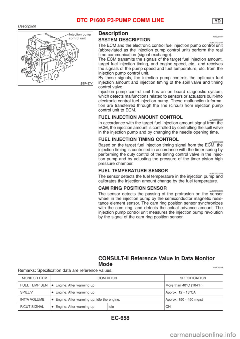
DescriptionNJEC0707SYSTEM DESCRIPTIONNJEC0707S01The ECM and the electronic control fuel injection pump control unit
(abbreviated as the injection pump control unit) perform the real
time communication (signal exchange).
The ECM transmits the signals of the target fuel injection amount,
target fuel injection timing, and engine speed, etc., and receives
the signals of the pump speed and fuel temperature, etc. from the
injection pump control unit.
By those signals, the injection pump controls the optimum fuel
injection amount and injection timing of the spill valve and timing
control valve.
Injection pump control unit has an on board diagnostic system,
which detects malfunctions related to sensors or actuators built-into
electronic control fuel injection pump. These malfunction informa-
tion are transferred through the line (circuit) from injection pump
control unit to ECM.
FUEL INJECTION AMOUNT CONTROLNJEC0707S02In accordance with the target fuel injection amount signal from the
ECM, the injection amount is controlled by controlling the spill valve
in the injection pump and by changing the needle opening time.
FUEL INJECTION TIMING CONTROLNJEC0707S03Based on the target fuel injection timing signal from the ECM, the
injection timing is controlled in accordance with the timer spring by
performing the duty control of the timing control valve in the injec-
tion pump and by adjusting the pressure of the timer piston high
pressure chamber.
FUEL TEMPERATURE SENSORNJEC0707S04The sensor detects the fuel temperature in the injection pump and
calibrates the injection amount change by the fuel temperature.
CAM RING POSITION SENSORNJEC0707S05The sensor detects the passing of the protrusion on the sensor
wheel in the injection pump by the semiconductor magnetic resis-
tance element sensor. The cam ring position sensor synchronizes
with the cam ring, and detects the actual advance amount. The
injection pump control unit measures the injection pump revolution
by the signal of the cam ring position sensor.
CONSULT-II Reference Value in Data Monitor
Mode
NJEC0708Remarks: Specification data are reference values.
MONITOR ITEM CONDITION SPECIFICATION
FUEL TEMP SEN+Engine: After warming up More than 40ÉC (104ÉF)
SPILL/V+Engine: After warming up Approx. 12 - 13ÉCA
INT/A VOLUME+Engine: After warming up, idle the engine. Approx. 150 - 450 mg/st
F/CUT SIGNAL+Engine: After warming up Idle ON
DTC P1600 P3´PUMP COMM LINEYD
Description
EC-658
Page 970 of 2493
SEF437Y
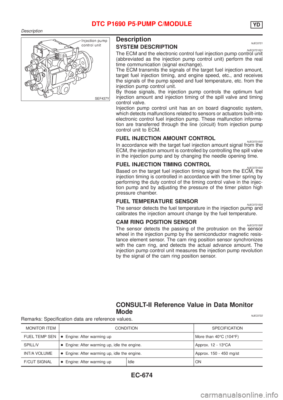
DescriptionNJEC0721SYSTEM DESCRIPTIONNJEC0721S01The ECM and the electronic control fuel injection pump control unit
(abbreviated as the injection pump control unit) perform the real
time communication (signal exchange).
The ECM transmits the signals of the target fuel injection amount,
target fuel injection timing, and engine speed, etc., and receives
the signals of the pump speed and fuel temperature, etc. from the
injection pump control unit.
By those signals, the injection pump controls the optimum fuel
injection amount and injection timing of the spill valve and timing
control valve.
Injection pump control unit has an on board diagnostic system,
which detects malfunctions related to sensors or actuators built-into
electronic control fuel injection pump. These malfunction informa-
tion are transferred through the line (circuit) from injection pump
control unit to ECM.
FUEL INJECTION AMOUNT CONTROLNJEC0721S02In accordance with the target fuel injection amount signal from the
ECM, the injection amount is controlled by controlling the spill valve
in the injection pump and by changing the needle opening time.
FUEL INJECTION TIMING CONTROLNJEC0721S03Based on the target fuel injection timing signal from the ECM, the
injection timing is controlled in accordance with the timer spring by
performing the duty control of the timing control valve in the injec-
tion pump and by adjusting the pressure of the timer piston high
pressure chamber.
FUEL TEMPERATURE SENSORNJEC0721S04The sensor detects the fuel temperature in the injection pump and
calibrates the injection amount change by the fuel temperature.
CAM RING POSITION SENSORNJEC0721S05The sensor detects the passing of the protrusion on the sensor
wheel in the injection pump by the semiconductor magnetic resis-
tance element sensor. The cam ring position sensor synchronizes
with the cam ring, and detects the actual advance amount. The
injection pump control unit measures the injection pump revolution
by the signal of the cam ring position sensor.
CONSULT-II Reference Value in Data Monitor
Mode
NJEC0722Remarks: Specification data are reference values.
MONITOR ITEM CONDITION SPECIFICATION
FUEL TEMP SEN+Engine: After warming up More than 40ÉC (104ÉF)
SPILL/V+Engine: After warming up, idle the engine. Approx. 12 - 13ÉCA
INT/A VOLUME+Engine: After warming up, idle the engine. Approx. 150 - 450 mg/st
F/CUT SIGNAL+Engine: After warming up Idle ON
DTC P1690 P5´PUMP C/MODULEYD
Description
EC-674
Page 983 of 2493

CONSULT-II Reference Value in Data Monitor
Mode
NJEC0765Specification data are reference values.
MONITOR ITEM CONDITION SPECIFICATION
EGR VOL CON/V+Engine: After warming up
+Air conditioner switch: ªOFFº
+Shift lever: Neutral position
+No-loadAfter one minute at idle More than 10 step
Revving engine up to 3,200 rpm 0 step
ECM Terminals and Reference ValueNJEC0766Specification data are reference values and are measured between each terminal and ground.
CAUTION:
Do not use ECM ground terminals when measuring input/output voltage. Doing so may result in dam-
age to the ECM's transistor. Use a ground other than ECM terminals, such as the ground.
TERMI-
NAL
NO.WIRE
COLORITEM CONDITION DATA(DC Voltage)
337
338
350
351W/L
PU/W
GY
OR/BEGR volume control valve[Engine is running]
+Warm-up condition
+Idle speed0.1 - 14V
(Voltage signals of each
ECM terminals differ
according to the control
position of EGR volume
control valve.)
EGR VOLUME CONTROL SYSTEMYD
CONSULT-II Reference Value in Data Monitor Mode
EC-687
Page 985 of 2493
Diagnostic ProcedureNJEC0768
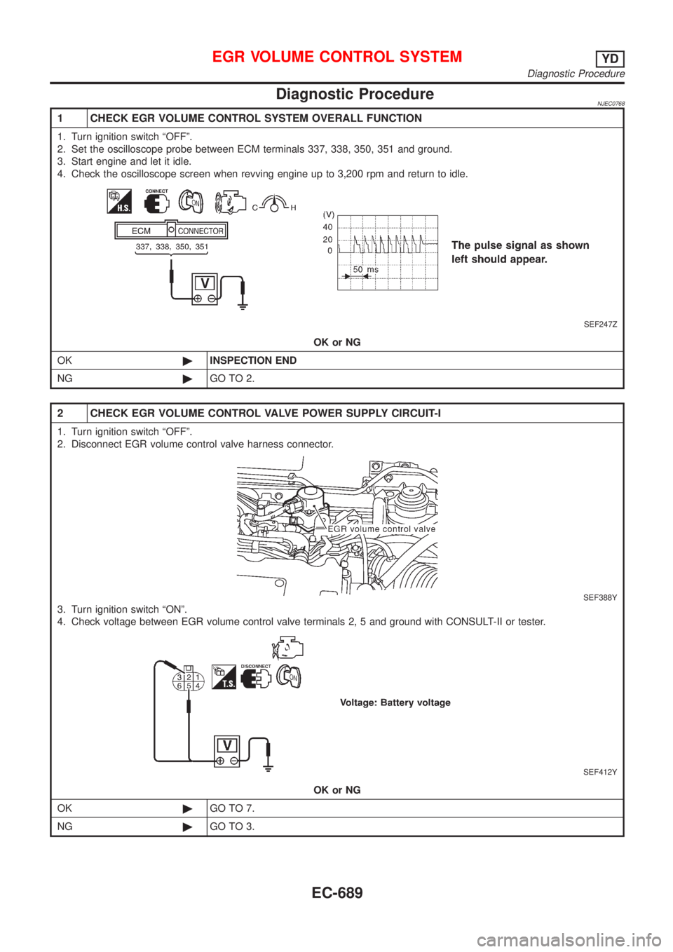
1 CHECK EGR VOLUME CONTROL SYSTEM OVERALL FUNCTION
1. Turn ignition switch ªOFFº.
2. Set the oscilloscope probe between ECM terminals 337, 338, 350, 351 and ground.
3. Start engine and let it idle.
4. Check the oscilloscope screen when revving engine up to 3,200 rpm and return to idle.
SEF247Z
OK or NG
OK©INSPECTION END
NG©GO TO 2.
2 CHECK EGR VOLUME CONTROL VALVE POWER SUPPLY CIRCUIT-I
1. Turn ignition switch ªOFFº.
2. Disconnect EGR volume control valve harness connector.
SEF388Y
3. Turn ignition switch ªONº.
4. Check voltage between EGR volume control valve terminals 2, 5 and ground with CONSULT-II or tester.
SEF412Y
OK or NG
OK©GO TO 7.
NG©GO TO 3.
EGR VOLUME CONTROL SYSTEMYD
Diagnostic Procedure
EC-689
Page 998 of 2493
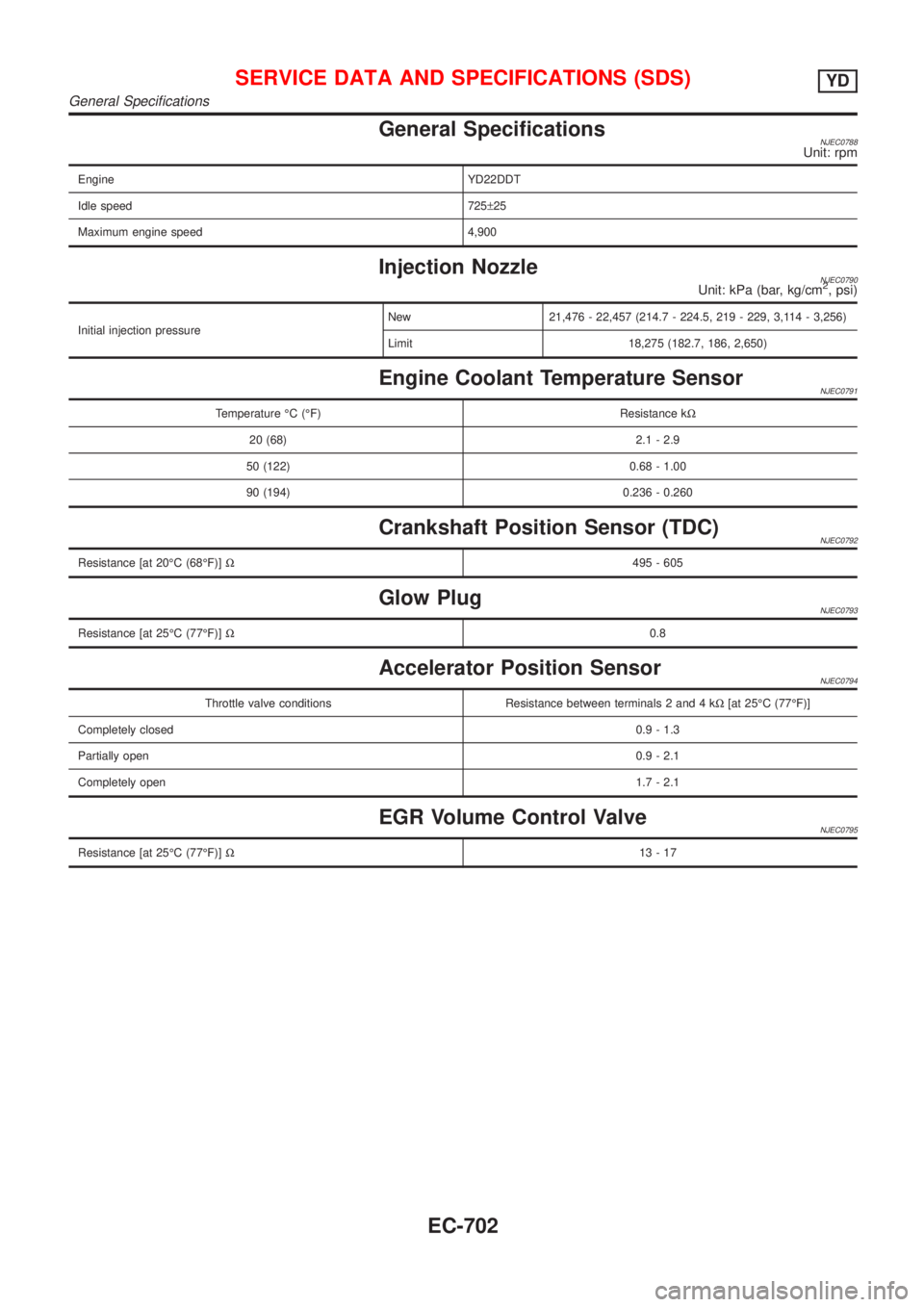
General SpecificationsNJEC0788Unit: rpm
Engine YD22DDT
Idle speed 725±25
Maximum engine speed 4,900
Injection NozzleNJEC0790Unit: kPa (bar, kg/cm2, psi)
Initial injection pressureNew 21,476 - 22,457 (214.7 - 224.5, 219 - 229, 3,114 - 3,256)
Limit 18,275 (182.7, 186, 2,650)
Engine Coolant Temperature SensorNJEC0791
Temperature ÉC (ÉF) Resistance kW
20 (68) 2.1 - 2.9
50 (122) 0.68 - 1.00
90 (194) 0.236 - 0.260
Crankshaft Position Sensor (TDC)NJEC0792
Resistance [at 20ÉC (68ÉF)]W495 - 605
Glow PlugNJEC0793
Resistance [at 25ÉC (77ÉF)]W0.8
Accelerator Position SensorNJEC0794
Throttle valve conditions Resistance between terminals 2 and 4 kW[at 25ÉC (77ÉF)]
Completely closed0.9 - 1.3
Partially open0.9 - 2.1
Completely open1.7 - 2.1
EGR Volume Control ValveNJEC0795
Resistance [at 25ÉC (77ÉF)]W13-17
SERVICE DATA AND SPECIFICATIONS (SDS)YD
General Specifications
EC-702
Page 1001 of 2493

Removal and InstallationNJFE0002CAUTION:
+When removing accelerator wire, make a mark to indicate lock nut's initial position.
+Check that throttle valve opens fully when accelerator pedal is fully depressed. Also check that it
returns to idle position when pedal is released.
+Check accelerator control parts for improper contact with any adjacent parts.
+When connecting accelerator wire, be careful not to twist or scratch wire.
YFE012
SEF793WB
Adjusting Accelerator WireNJFE00031. Remove the vacuum hose connected to the throttle opener.
2. Connect suitable vacuum hose to vacuum pump as shown left.
3. Apply vacuum [more than þ40.0 kPa (þ400 mbar, þ300 mmHg,
þ11.81 inHg)] until the throttle drum becomes free from the rod
of the throttle opener.
Make sure that there is clearance between the throttle
drum and rod.
If NG, refer to EC-164, ªBasic Inspectionº.
If OK, go to following step.
ACCELERATOR CONTROL SYSTEMQG
Removal and Installation
FE-3
Page 1189 of 2493
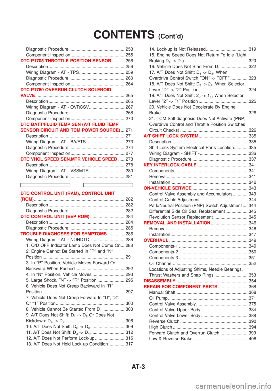
Diagnostic Procedure ..............................................253
Component Inspection .............................................255
DTC P1705 THROTTLE POSITION SENSOR...........256
Description ...............................................................256
Wiring Diagram - AT - TPS ......................................259
Diagnostic Procedure ..............................................260
Component Inspection .............................................264
DTC P1760 OVERRUN CLUTCH SOLENOID
VALVE..........................................................................265
Description ...............................................................265
Wiring Diagram - AT - OVRCSV..............................267
Diagnostic Procedure ..............................................268
Component Inspection .............................................270
DTC BATT/FLUID TEMP SEN (A/T FLUID TEMP
SENSOR CIRCUIT AND TCM POWER SOURCE)....271
Description ...............................................................271
Wiring Diagram - AT - BA/FTS ................................273
Diagnostic Procedure ..............................................274
Component Inspection .............................................277
DTC VHCL SPEED SEN.MTR VEHICLE SPEED......278
Description ...............................................................278
Wiring Diagram - AT - VSSMTR ..............................280
Diagnostic Procedure ..............................................281
DTC CONTROL UNIT (RAM), CONTROL UNIT
(ROM)...........................................................................282
Description ...............................................................282
Diagnostic Procedure ..............................................282
DTC CONTROL UNIT (EEP ROM).............................284
Description ...............................................................284
Diagnostic Procedure ..............................................285
TROUBLE DIAGNOSES FOR SYMPTOMS...............286
Wiring Diagram - AT - NONDTC .............................286
1. O/D OFF Indicator Lamp Does Not Come On....288
2. Engine Cannot Be Started In²P²and²N²
Position ....................................................................291
3. In²P²Position, Vehicle Moves Forward Or
Backward When Pushed .........................................292
4. In²N²Position, Vehicle Moves ...........................293
5. Large Shock.²N²->²R²Position .......................295
6. Vehicle Does Not Creep Backward In²R²
Position ....................................................................297
7. Vehicle Does Not Creep Forward In²D²,²2²
Or²1²Position .........................................................300
8. Vehicle Cannot Be Started From D
1...................303
9. A/T Does Not Shift: D
1-> D2Or Does Not
Kickdown: D
4-> D2..................................................306
10. A/T Does Not Shift: D
2-> D3.............................309
11. A/T Does Not Shift: D
3-> D4.............................312
12. A/T Does Not Perform Lock-up .........................315
13. A/T Does Not Hold Lock-up Condition ..............31714. Lock-up Is Not Released ...................................319
15. Engine Speed Does Not Return To Idle (Light
Braking D
4-> D3).....................................................320
16. Vehicle Does Not Start From D
1.......................322
17. A/T Does Not Shift: D
4-> D3, When
Overdrive Control Switch²ON²->²OFF²...............323
18. A/T Does Not Shift: D
3-> 22, When Selector
Lever²D²->²2²Position.........................................324
19. A/T Does Not Shift: 2
2-> 11, When Selector
Lever²2²->²1²Position .........................................325
20. Vehicle Does Not Decelerate By Engine
Brake........................................................................326
21. TCM Self-diagnosis Does Not Activate (PNP,
Overdrive Control and Throttle Position Switches
Circuit Checks) ........................................................326
A/T SHIFT LOCK SYSTEM.........................................335
Description ...............................................................335
Shift Lock System Electrical Parts Location............335
Wiring Diagram - SHIFT -........................................336
Diagnostic Procedure ..............................................337
KEY INTERLOCK CABLE..........................................341
Components.............................................................341
Removal ...................................................................341
Installation ................................................................342
ON-VEHICLE SERVICE..............................................343
Control Valve Assembly and Accumulators .............343
Control Cable Adjustment ........................................344
Park/Neutral Position (PNP) Switch Adjustment .....344
Differential Side Oil Seal Replacement ...................345
Revolution Sensor Replacement .............................345
REMOVAL AND INSTALLATION...............................346
Removal ...................................................................346
Installation ................................................................347
OVERHAUL.................................................................349
Components-1 .........................................................349
Components-2 .........................................................350
Components-3 .........................................................351
Oil Channel ..............................................................352
Locations of Adjusting Shims, Needle Bearings,
Thrust Washers and Snap Rings ............................353
DISASSEMBLY............................................................354
REPAIR FOR COMPONENT PARTS.........................368
Manual Shaft............................................................368
Oil Pump ..................................................................371
Control Valve Assembly ...........................................375
Control Valve Upper Body .......................................384
Control Valve Lower Body .......................................388
Reverse Clutch ........................................................390
High Clutch ..............................................................394
Forward Clutch and Overrun Clutch........................399
Low & Reverse Brake..............................................406
CONTENTS(Cont'd)
AT-3
Page 1190 of 2493
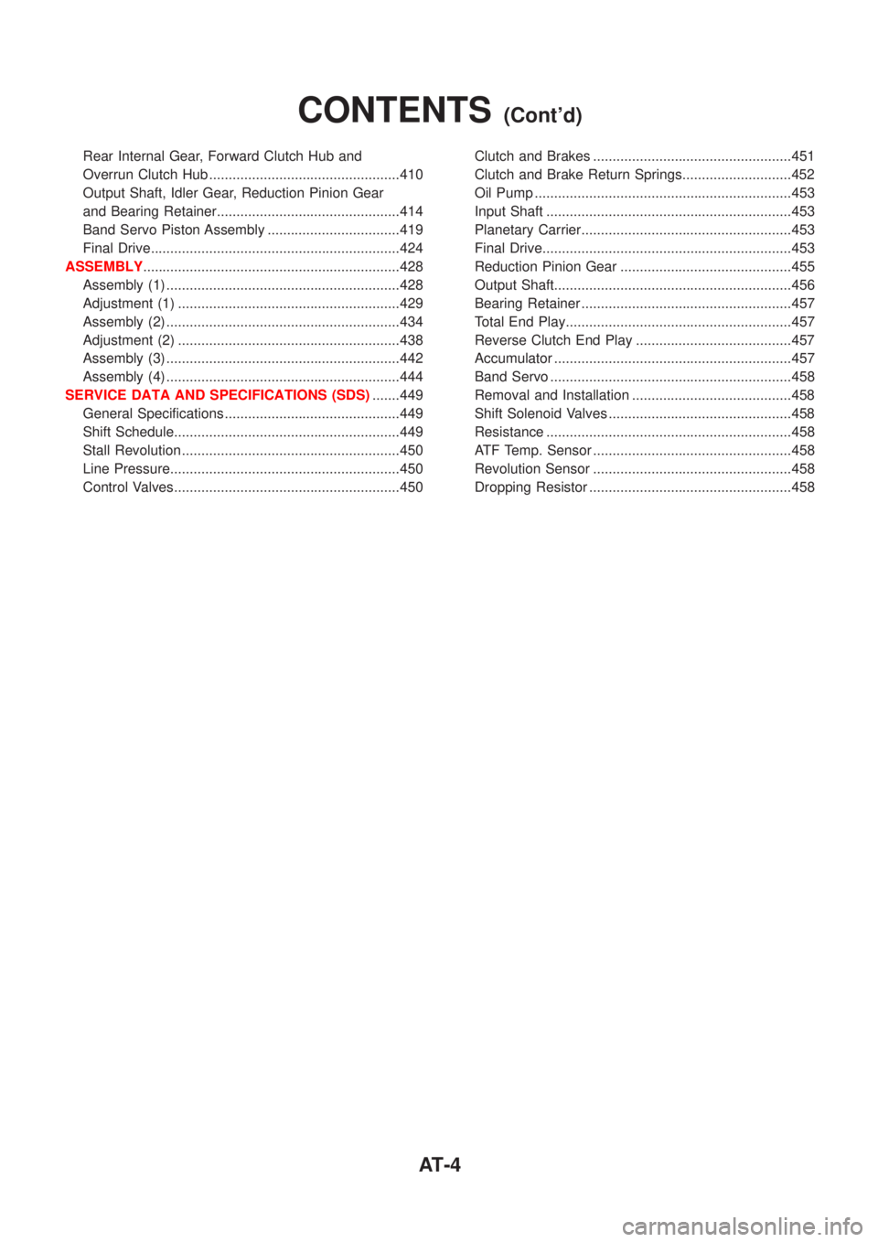
Rear Internal Gear, Forward Clutch Hub and
Overrun Clutch Hub .................................................410
Output Shaft, Idler Gear, Reduction Pinion Gear
and Bearing Retainer...............................................414
Band Servo Piston Assembly ..................................419
Final Drive................................................................424
ASSEMBLY..................................................................428
Assembly (1) ............................................................428
Adjustment (1) .........................................................429
Assembly (2) ............................................................434
Adjustment (2) .........................................................438
Assembly (3) ............................................................442
Assembly (4) ............................................................444
SERVICE DATA AND SPECIFICATIONS (SDS).......449
General Specifications .............................................449
Shift Schedule..........................................................449
Stall Revolution ........................................................450
Line Pressure...........................................................450
Control Valves..........................................................450Clutch and Brakes ...................................................451
Clutch and Brake Return Springs............................452
Oil Pump ..................................................................453
Input Shaft ...............................................................453
Planetary Carrier......................................................453
Final Drive................................................................453
Reduction Pinion Gear ............................................455
Output Shaft.............................................................456
Bearing Retainer ......................................................457
Total End Play..........................................................457
Reverse Clutch End Play ........................................457
Accumulator .............................................................457
Band Servo ..............................................................458
Removal and Installation .........................................458
Shift Solenoid Valves ...............................................458
Resistance ...............................................................458
ATF Temp. Sensor ...................................................458
Revolution Sensor ...................................................458
Dropping Resistor ....................................................458
CONTENTS(Cont'd)
AT-4