Page 721 of 2493
12 CHECK INTERMITTENT INCIDENT
Perform ªTROUBLE DIAGNOSIS FOR INTERMITTENT INCIDENTº, EC-144.
©INSPECTION END
SEF605Y
SEF089X
Component InspectionNJEC1763IACV-AAC VALVENJEC1763S011) Disconnect IACV-AAC valve harness connector.
2) Check IACV-AAC valve resistance.
Condition Resistance
Terminal 2 and terminals 1, 3
20-24W[at 20ÉC (68ÉF)]
Terminal 5 and terminals 4, 6
3) Reconnect IACV-AAC valve harness connector.
4) Remove idle air adjusting unit assembly (IACV-AAC valve is
built-in) from engine.
(The IACV-AAC valve harness connector should remain con-
nected.)
5) Turn ignition switch ªONº and ªOFFº, and ensure the IACV-
AAC valve shaft smoothly moves forward and backward,
according to the ignition switch position.
If NG, replace the IACV-AAC valve.
IDLE AIR CONTROL VALVE (IACV) Ð AUXILIARY AIR CONTROL
(AAC) VALVE
QG
Diagnostic Procedure (Cont'd)
EC-425
Page 728 of 2493

SEF095X
Component DescriptionNJEC1769The valve timing control system is utilized to control intake valve
opening and closing timing. Engine coolant temperature signals,
engine speed and throttle position are used to determine intake
valve timing.
The intake camshaft sprocket position is regulated by oil pressure
controlled by the intake valve timing control.
When ECM sends ON signal to intake valve timing control solenoid
valve, oil pressure is transmitted to camshaft sprocket. Then, intake
side camshaft is advanced.
OperationNJEC1770
Engine operating condition
Intake valve tim-
ing control sole-
noid valveIntake valve
opening and
closing timeValve overlap
Engine coolant
temperatureEngine speed B/FUEL SCHDL Neutral switch
20ÉC (68ÉF) -
70ÉC (158ÉF)
1,150 - 4,600
rpmAbove 3 msec
OFF ON Advance Increased
Above 70ÉC
(158ÉF)Above 7 msec
Conditions other than those above OFF Normal Normal
CONSULT-II Reference Value in Data Monitor
Mode
NJEC1771
MONITOR ITEM CONDITION SPECIFICATION
INT/V SOL-B1+Engine: After warming up
+Lift up vehicle and suitable gear
positionIdle OFF
Revving engine from 2,000 to
3,000 rpmON
ECM Terminals and Reference ValueNJEC1772Specification data are reference values and are measured between each terminal and ground.
CAUTION:
Do not use ECM ground terminals when measuring input/output voltage. Doing so may result in dam-
age to the ECM's transistor. Use a ground other than ECM terminals, such as the ground.
TERMI-
NAL
NO.WIRE
COLORITEM CONDITION DATA (DC Voltage)
1 Y/RIntake valve timing control
solenoid valve[Engine is running]
+Idle speedBATTERY VOLTAGE
(11 - 14V)
[Engine is running]
+Warm-up condition
+Lift up vehicle and suitable gear position
+Rev engine from 2,000 to 3,000 rpmApproximately 0V
INTAKE VALVE TIMING CONTROL SOLENOID VALVEQG
Component Description
EC-432
Page 742 of 2493
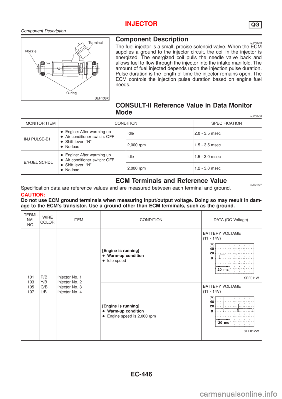
SEF138X
Component DescriptionNJEC0435The fuel injector is a small, precise solenoid valve. When the ECM
supplies a ground to the injector circuit, the coil in the injector is
energized. The energized coil pulls the needle valve back and
allows fuel to flow through the injector into the intake manifold. The
amount of fuel injected depends upon the injection pulse duration.
Pulse duration is the length of time the injector remains open. The
ECM controls the injection pulse duration based on engine fuel
needs.
CONSULT-II Reference Value in Data Monitor
Mode
NJEC0436
MONITOR ITEM CONDITION SPECIFICATION
INJ PULSE-B1+Engine: After warming up
+Air conditioner switch: OFF
+Shift lever: ªNº
+No-loadIdle 2.0 - 3.5 msec
2,000 rpm 1.5 - 3.5 msec
B/FUEL SCHDL+Engine: After warming up
+Air conditioner switch: OFF
+Shift lever: ªNº
+No-loadIdle 1.5 - 3.0 msec
2,000 rpm 1.2 - 3.0 msec
ECM Terminals and Reference ValueNJEC0437Specification data are reference values and are measured between each terminal and ground.
CAUTION:
Do not use ECM ground terminals when measuring input/output voltage. Doing so may result in dam-
age to the ECM's transistor. Use a ground other than ECM terminals, such as the ground.
TERMI-
NAL
NO.WIRE
COLORITEM CONDITION DATA (DC Voltage)
101
103
105
107R/B
Y/B
G/B
L/BInjector No. 1
Injector No. 2
Injector No. 3
Injector No. 4[Engine is running]
+Warm-up condition
+Idle speedBATTERY VOLTAGE
(11 - 14V)
SEF011W
[Engine is running]
+Warm-up condition
+Engine speed is 2,000 rpmBATTERY VOLTAGE
(11 - 14V)
SEF012W
INJECTORQG
Component Description
EC-446
Page 801 of 2493
Fuel Injection Control System
DESCRIPTIONNJEC0612System DescriptionNJEC0612S01Three types of fuel injection control are provided to accommodate engine operating conditions; normal control,
idle control and start control. The ECM determines the appropriate fuel injection control. Under each control,
the amount of fuel injected is compensated to improve engine performance.
Pulse signals are exchanged between ECM and electronic control fuel injection pump (control unit is built-in).
The fuel injection pump control unit performs duty control on the spill valve (built into the fuel injection pump)
according to the input signals to compensate the amount of fuel injected to the preset value.
Start ControlNJEC0612S02Input/Output Signal ChartNJEC0612S0201
Sensor Input Signal to ECM ECM Function Actuator
Engine coolant temperature sensor Engine coolant temperature
Fuel injection
control (start
control)Electronic control fuel
injection pump Crankshaft position sensor (TDC) Engine speed
Ignition switch Start signal
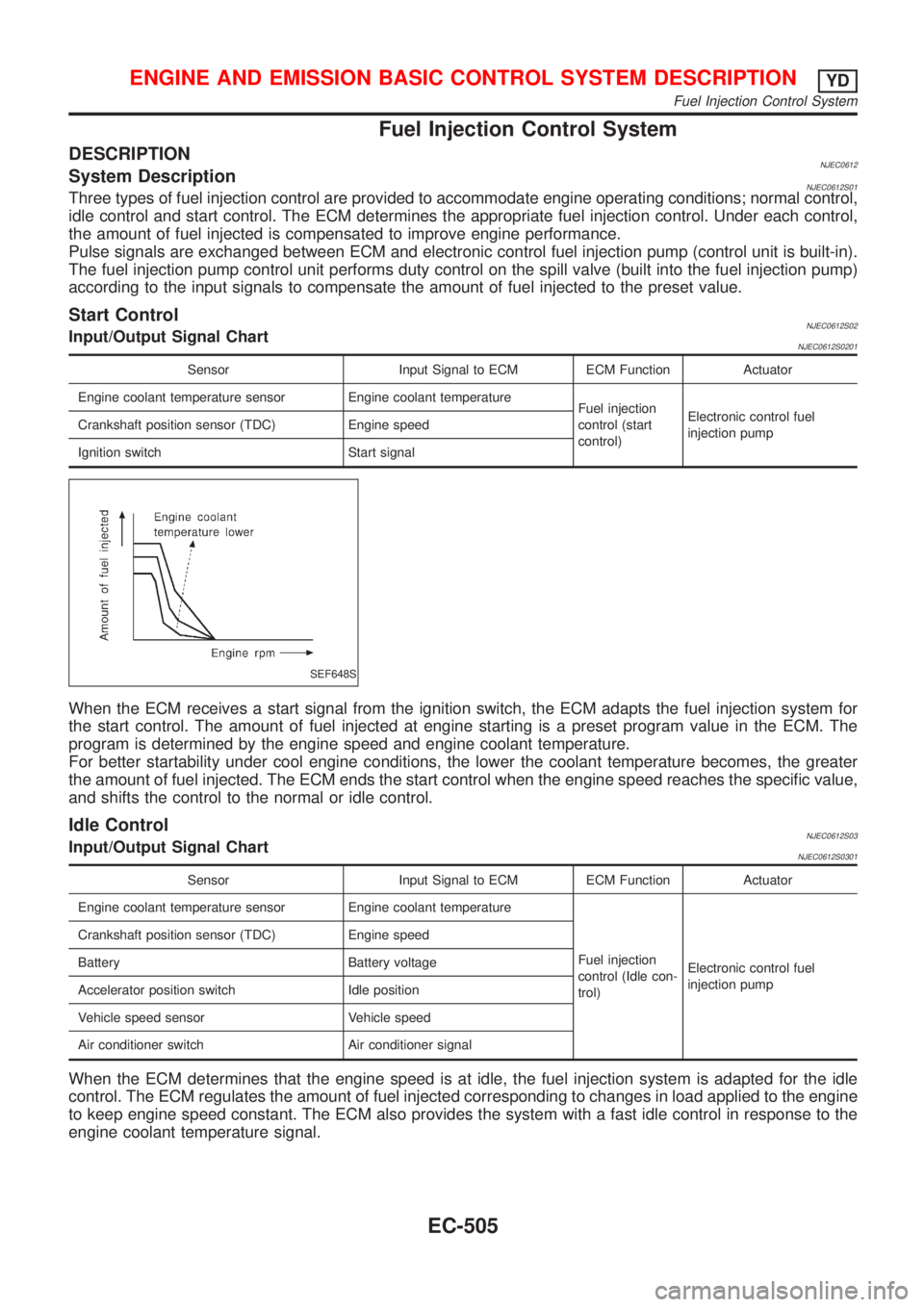
SEF648S
When the ECM receives a start signal from the ignition switch, the ECM adapts the fuel injection system for
the start control. The amount of fuel injected at engine starting is a preset program value in the ECM. The
program is determined by the engine speed and engine coolant temperature.
For better startability under cool engine conditions, the lower the coolant temperature becomes, the greater
the amount of fuel injected. The ECM ends the start control when the engine speed reaches the specific value,
and shifts the control to the normal or idle control.
Idle ControlNJEC0612S03Input/Output Signal ChartNJEC0612S0301
Sensor Input Signal to ECM ECM Function Actuator
Engine coolant temperature sensor Engine coolant temperature
Fuel injection
control (Idle con-
trol)Electronic control fuel
injection pump Crankshaft position sensor (TDC) Engine speed
Battery Battery voltage
Accelerator position switch Idle position
Vehicle speed sensor Vehicle speed
Air conditioner switch Air conditioner signal
When the ECM determines that the engine speed is at idle, the fuel injection system is adapted for the idle
control. The ECM regulates the amount of fuel injected corresponding to changes in load applied to the engine
to keep engine speed constant. The ECM also provides the system with a fast idle control in response to the
engine coolant temperature signal.
ENGINE AND EMISSION BASIC CONTROL SYSTEM DESCRIPTIONYD
Fuel Injection Control System
EC-505
Page 837 of 2493
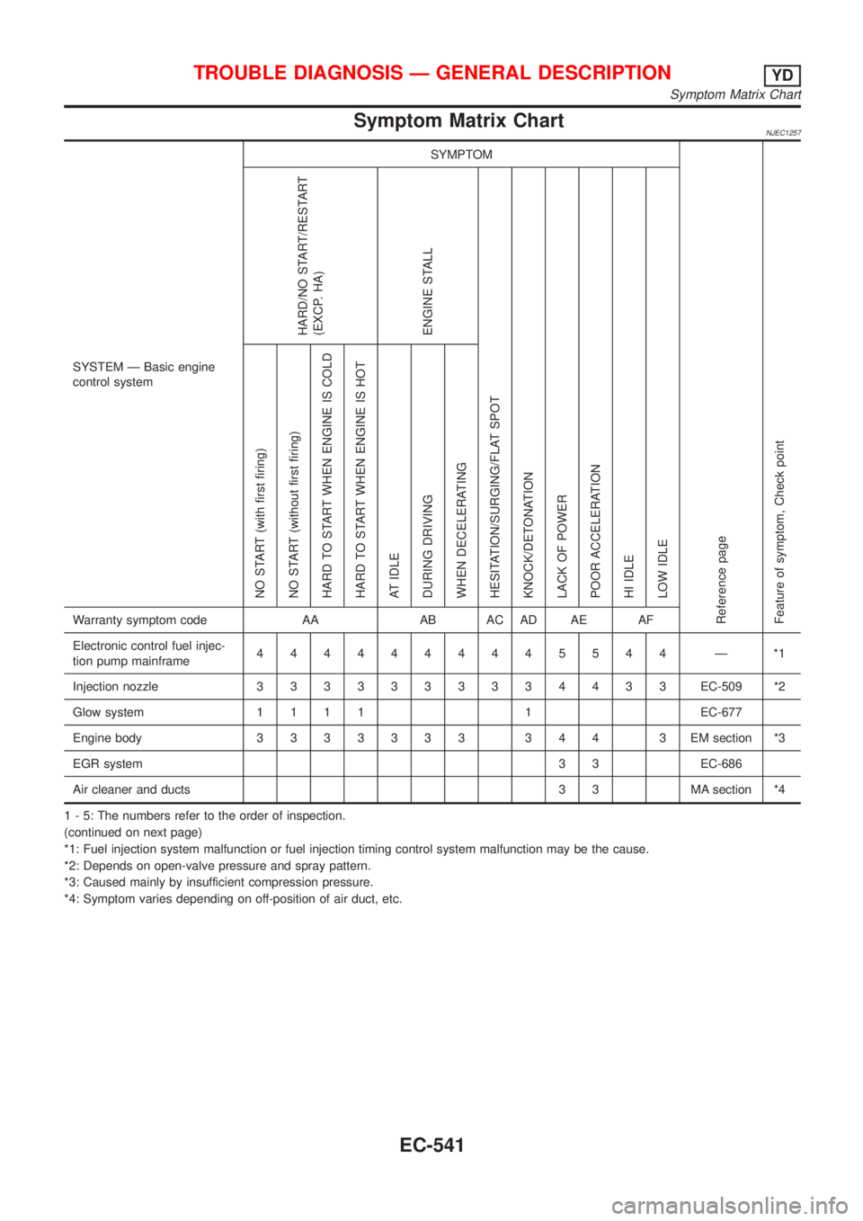
Symptom Matrix ChartNJEC1257
SYSTEM Ð Basic engine
control systemSYMPTOM
Reference page
Feature of symptom, Check pointHARD/NO START/RESTART
(EXCP. HA)
ENGINE STALL
HESITATION/SURGING/FLAT SPOT
KNOCK/DETONATION
LACK OF POWER
POOR ACCELERATION
HI IDLE
LOW IDLE NO START (with first firing)
NO START (without first firing)
HARD TO START WHEN ENGINE IS COLD
HARD TO START WHEN ENGINE IS HOT
AT IDLE
DURING DRIVING
WHEN DECELERATINGWarranty symptom code AA AB AC AD AE AF
Electronic control fuel injec-
tion pump mainframe4444444445544 Ð *1
Injection nozzle3333333334433EC-509 *2
Glow system1111 1EC-677
Engine body3333333 344 3EMsection *3
EGR system3 3 EC-686
Air cleaner and ducts 3 3 MA section *4
1 - 5: The numbers refer to the order of inspection.
(continued on next page)
*1: Fuel injection system malfunction or fuel injection timing control system malfunction may be the cause.
*2: Depends on open-valve pressure and spray pattern.
*3: Caused mainly by insufficient compression pressure.
*4: Symptom varies depending on off-position of air duct, etc.
TROUBLE DIAGNOSIS Ð GENERAL DESCRIPTIONYD
Symptom Matrix Chart
EC-541
Page 838 of 2493

SYSTEM Ð Basic engine control
systemSYMPTOM
Reference page
Feature of symptom, Check pointROUGH IDLE/HUNTING
IDLING VIBRATION
SLOW/NO RETURN TO IDLE
OVERHEAT/HIGH ENGINE COOLANT TEMPERATURE
EXCESSIVE FUEL CONSUMPTION
EXCESSIVE OIL CONSUMPTION
ABNORMAL SMOKE COLOR
DEAD BATTERY (UNDER CHARGE)
Malfunction indicator illuminates.
Can be detected by CONSULT-II?BLACK SMOKE
WHITE SMOKEWarranty symptom code AG AH AJ AK AL AM AP HA
Electronic control fuel injection
pump mainframe44345433Ð*1
Injection nozzle 3 3 3 4 3 EC-509 *2
Glow system 1 1 EC-677
Engine body 3 3 3 3 3 3 EM section *3
EGR system 3 EC-686
Air cleaner and ducts 3 3 MA section *4
1 - 5: The numbers refer to the order of inspection.
(continued on next page)
*1: Fuel injection system malfunction or fuel injection timing control system malfunction may be the cause.
*2: Depends on open-valve pressure and spray pattern.
*3: Caused mainly by insufficient compression pressure.
*4: Symptom varies depending on off-position of air duct, etc.
TROUBLE DIAGNOSIS Ð GENERAL DESCRIPTIONYD
Symptom Matrix Chart (Cont'd)
EC-542
Page 845 of 2493
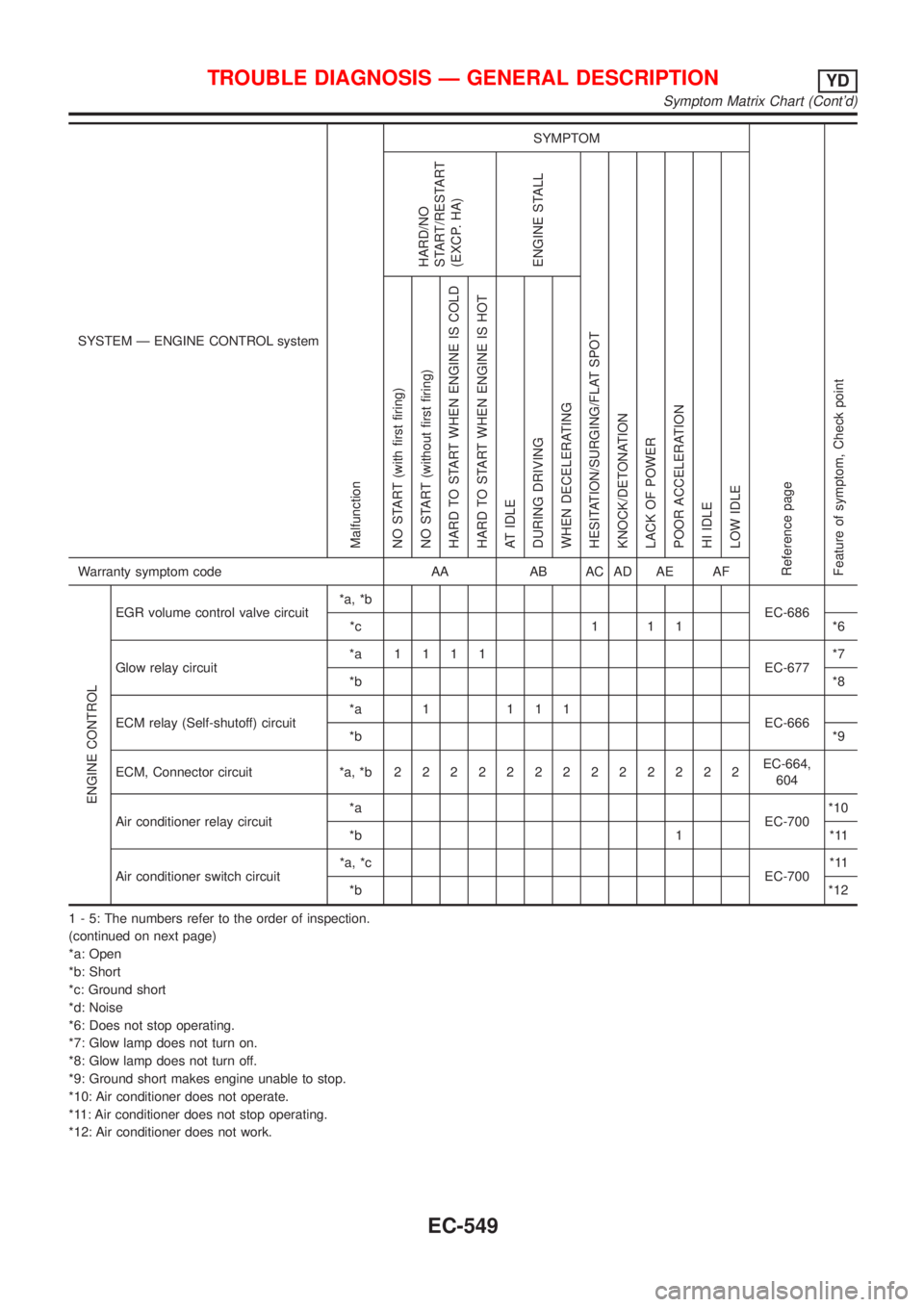
SYSTEM Ð ENGINE CONTROL system
Malfunction
SYMPTOM
Reference page
Feature of symptom, Check pointHARD/NO
START/RESTART
(EXCP. HA)
ENGINE STALL
HESITATION/SURGING/FLAT SPOT
KNOCK/DETONATION
LACK OF POWER
POOR ACCELERATION
HI IDLE
LOW IDLE NO START (with first firing)
NO START (without first firing)
HARD TO START WHEN ENGINE IS COLD
HARD TO START WHEN ENGINE IS HOT
AT IDLE
DURING DRIVING
WHEN DECELERATINGWarranty symptom code AA AB AC AD AE AF
ENGINE CONTROL
EGR volume control valve circuit*a, *b
EC-686
*c 1 1 1 *6
Glow relay circuit*a 1111
EC-677*7
*b*8
ECM relay (Self-shutoff) circuit*a 1 111
EC-666
*b*9
ECM, Connector circuit *a, *b2222222222222EC-664,
604
Air conditioner relay circuit*a
EC-700*10
*b 1 *11
Air conditioner switch circuit*a, *c
EC-700*11
*b*12
1 - 5: The numbers refer to the order of inspection.
(continued on next page)
*a: Open
*b: Short
*c: Ground short
*d: Noise
*6: Does not stop operating.
*7: Glow lamp does not turn on.
*8: Glow lamp does not turn off.
*9: Ground short makes engine unable to stop.
*10: Air conditioner does not operate.
*11: Air conditioner does not stop operating.
*12: Air conditioner does not work.
TROUBLE DIAGNOSIS Ð GENERAL DESCRIPTIONYD
Symptom Matrix Chart (Cont'd)
EC-549
Page 846 of 2493
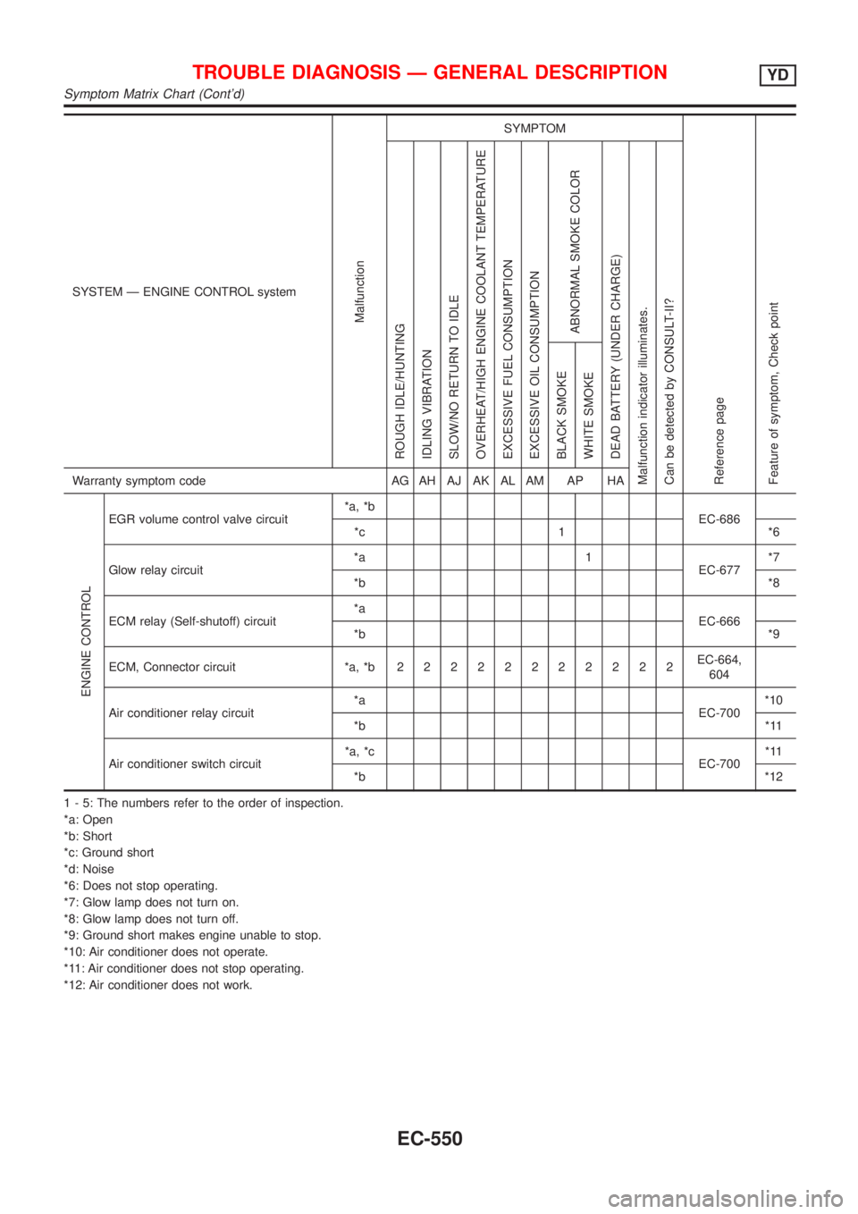
SYSTEM Ð ENGINE CONTROL system
Malfunction
SYMPTOM
Reference page
Feature of symptom, Check pointROUGH IDLE/HUNTING
IDLING VIBRATION
SLOW/NO RETURN TO IDLE
OVERHEAT/HIGH ENGINE COOLANT TEMPERATURE
EXCESSIVE FUEL CONSUMPTION
EXCESSIVE OIL CONSUMPTION
ABNORMAL SMOKE COLOR
DEAD BATTERY (UNDER CHARGE)
Malfunction indicator illuminates.
Can be detected by CONSULT-II?BLACK SMOKE
WHITE SMOKEWarranty symptom code AG AH AJ AK AL AM AP HA
ENGINE CONTROL
EGR volume control valve circuit*a, *b
EC-686
*c 1 *6
Glow relay circuit*a 1
EC-677*7
*b*8
ECM relay (Self-shutoff) circuit*a
EC-666
*b*9
ECM, Connector circuit *a, *b22222222222EC-664,
604
Air conditioner relay circuit*a
EC-700*10
*b*11
Air conditioner switch circuit*a, *c
EC-700*11
*b*12
1 - 5: The numbers refer to the order of inspection.
*a: Open
*b: Short
*c: Ground short
*d: Noise
*6: Does not stop operating.
*7: Glow lamp does not turn on.
*8: Glow lamp does not turn off.
*9: Ground short makes engine unable to stop.
*10: Air conditioner does not operate.
*11: Air conditioner does not stop operating.
*12: Air conditioner does not work.
TROUBLE DIAGNOSIS Ð GENERAL DESCRIPTIONYD
Symptom Matrix Chart (Cont'd)
EC-550