2001 NISSAN ALMERA N16 Idle control valve
[x] Cancel search: Idle control valvePage 1636 of 2493

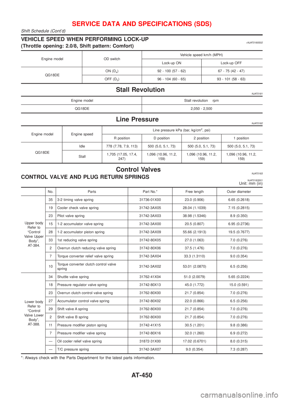
VEHICLE SPEED WHEN PERFORMING LOCK-UP=NJAT0180S02(Throttle opening: 2.0/8, Shift pattern: Comfort)
Engine model OD switchVehicle speed km/h (MPH)
Lock-up ON Lock-up OFF
QG18DEON (D
4) 92 - 100 (57 - 62) 67 - 75 (42 - 47)
OFF (D
3) 96 - 104 (60 - 65) 93 - 101 (58 - 63)
Stall RevolutionNJAT0181
Engine model Stall revolution rpm
QG18DE 2,050 - 2,500
Line PressureNJAT0182
Engine model Engine speedLine pressure kPa (bar, kg/cm
2, psi)
R position D position 2 position 1 position
QG18DEIdle 778 (7.78, 7.9, 113) 500 (5.0, 5.1, 73) 500 (5.0, 5.1, 73) 500 (5.0, 5.1, 73)
Stall1,705 (17.05, 17.4,
247)1,096 (10.96, 11.2,
159)1,096 (10.96, 11.2,
159)1,096 (10.96, 11.2,
159)
Control ValvesNJAT0183CONTROL VALVE AND PLUG RETURN SPRINGSNJAT0183S01Unit: mm (in)
No. Parts Part No.* Free length Outer diameter
Upper body
Refer to
ªControl
Valve Upper
Bodyº,
AT-384.35 3-2 timing valve spring 31736-01X00 23.0 (0.906) 6.65 (0.2618)
19 Cooler check valve spring 31742-3AX05 28.04 (1.1039) 7.15 (0.2815)
23 Pilot valve spring 31742-3AX03 38.98 (1.5346) 8.9 (0.350)
15 1-2 accumulator valve spring 31742-3AX00 20.5 (0.807) 6.95 (0.2736)
28 1-2 accumulator piston spring 31742-3AX09 55.66 (2.1913) 19.5 (0.7677)
33 1st reducing valve spring 31742-80X05 27.0 (1.063) 7.0 (0.276)
2 Overrun clutch reducing valve spring 31742-80X06 37.5 (1.476) 7.0 (0.276)
7 Torque converter relief valve spring 31742-3AX04 33.3 (1.3110) 9.0 (0.354)
10Torque converter clutch control valve
spring31742-3AX02 53.01 (2.0870) 6.5 (0.256)
Lower body
Refer to
ªControl
Valve Lower
Bodyº,
AT-388.34 Shuttle valve spring 31762-41X04 51.0 (2.0079) 5.65 (0.2224)
18 Pressure regulator valve spring 31742-80X13 45.0 (1.772) 15.0 (0.591)
23 Overrun clutch control valve spring 31762-80X00 21.7 (0.854) 7.0 (0.276)
27 Accumulator control valve spring 31742-80X02 22.0 (0.866) 6.5 (0.256)
29 Shift valve A spring 31762-80X00 21.7 (0.854) 7.0 (0.276)
2 Shift valve B spring 31762-80X00 21.7 (0.854) 7.0 (0.276)
11 Pressure modifier piston spring 31742-41X15 30.5 (1.201) 9.8 (0.386)
7 Pressure modifier valve spring 31742-80X16 32.0 (1.260) 6.9 (0.272)
Ð Oil cooler relief valve spring 31872-31X00 17.02 (0.6701) 8.0 (0.315)
Ð T/C pressure spring 31742-3AX07 9.0 (0.354) 7.3 (0.287)
*: Always check with the Parts Department for the latest parts information.
SERVICE DATA AND SPECIFICATIONS (SDS)
Shift Schedule (Cont'd)
AT-450
Page 1799 of 2493

SST834-I
Checking Hydraulic SystemNJST0016Before starting, check belt tension, driving pulley and tire pressure.
1. Set Tool. Open shut-off valve. Then bleed air. Refer to ªBleed-
ing Hydraulic Systemº, ST-8.
2. Run engine at idle speed or 1,000 rpm.
Make sure temperature of fluid in tank rises to 60 to 80ÉC (140
to 176ÉF).
WARNING:
Warm up engine with shut-off valve fully opened. If engine is
started with shut-off valve closed, fluid pressure in oil pump
increases to maximum. This will raise oil temperature abnor-
mally.
3. Check pressure with steering wheel fully turned to left and right
positions with engine idling at 1,000 rpm.
CAUTION:
Do not hold the steering wheel in a locked position for more
than 15 seconds.
Oil pump maximum standard pressure:
QG15, 18 engine
8,600 - 9,200 kPa (86.0 - 92.0 bar, 88.7 - 93.8
kg/cm
2, 1,247 - 1,334 psi)
YD22 engine
8,800 - 9,400 kPa (88.0 - 94.0 bar, 88.7 - 95.8
kg/cm
2, 1,261 - 1,362 psi)
+If pressure reaches maximum operating pressure, system is
OK.
+If pressure increases above maximum operating pressure,
check power steering pump flow control valve. Refer to ST-25.
4. If power steering pressure is below the maximum operating
pressure, slowly close shut-off valve and check pressure
again.
CAUTION:
Do not close shut-off valve for more than 15 seconds.
+If pressure increases to maximum operating pressure, gear is
damaged. Refer to ªRemoval and Installationº, ST-16.
+If pressure remains below maximum operating pressure, pump
is damaged. Refer to ªDisassemblyº, ST-26.
5. After checking hydraulic system, remove Tool and add fluid as
necessary. Then completely bleed air out of system. Refer to
ST-8.
ON-VEHICLE SERVICE
Checking Hydraulic System
ST-9
Page 1973 of 2493

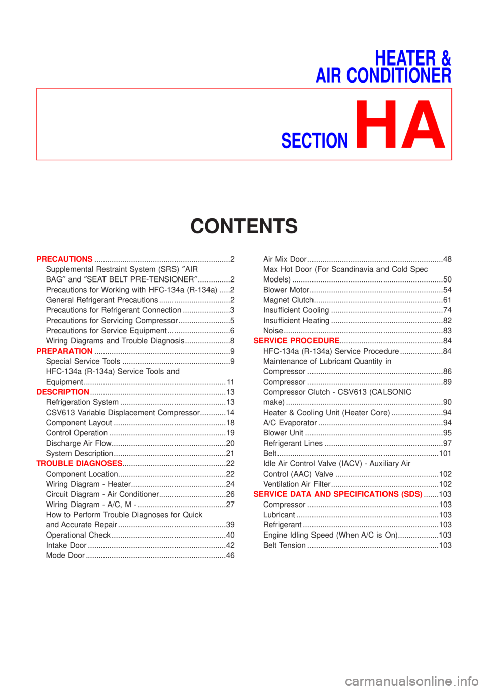
HEATER &
AIR CONDITIONER
SECTION
HA
CONTENTS
PRECAUTIONS...............................................................2
Supplemental Restraint System (SRS)²AIR
BAG²and²SEAT BELT PRE-TENSIONER²...............2
Precautions for Working with HFC-134a (R-134a) .....2
General Refrigerant Precautions .................................2
Precautions for Refrigerant Connection ......................3
Precautions for Servicing Compressor ........................5
Precautions for Service Equipment .............................6
Wiring Diagrams and Trouble Diagnosis .....................8
PREPARATION...............................................................9
Special Service Tools ..................................................9
HFC-134a (R-134a) Service Tools and
Equipment .................................................................. 11
DESCRIPTION...............................................................13
Refrigeration System .................................................13
CSV613 Variable Displacement Compressor............14
Component Layout ....................................................18
Control Operation ......................................................19
Discharge Air Flow.....................................................20
System Description ....................................................21
TROUBLE DIAGNOSES................................................22
Component Location..................................................22
Wiring Diagram - Heater............................................24
Circuit Diagram - Air Conditioner...............................26
Wiring Diagram - A/C, M - .........................................27
How to Perform Trouble Diagnoses for Quick
and Accurate Repair ..................................................39
Operational Check .....................................................40
Intake Door ................................................................42
Mode Door .................................................................46Air Mix Door ...............................................................48
Max Hot Door (For Scandinavia and Cold Spec
Models) ......................................................................50
Blower Motor..............................................................54
Magnet Clutch............................................................61
Insufficient Cooling ....................................................74
Insufficient Heating ....................................................82
Noise ..........................................................................83
SERVICE PROCEDURE................................................84
HFC-134a (R-134a) Service Procedure ....................84
Maintenance of Lubricant Quantity in
Compressor ...............................................................86
Compressor ...............................................................89
Compressor Clutch - CSV613 (CALSONIC
make) .........................................................................90
Heater & Cooling Unit (Heater Core) ........................94
A/C Evaporator ..........................................................94
Blower Unit ................................................................95
Refrigerant Lines .......................................................97
Belt ...........................................................................101
Idle Air Control Valve (IACV) - Auxiliary Air
Control (AAC) Valve ................................................102
Ventilation Air Filter ..................................................102
SERVICE DATA AND SPECIFICATIONS (SDS).......103
Compressor .............................................................103
Lubricant ..................................................................103
Refrigerant ...............................................................103
Engine Idling Speed (When A/C is On)...................103
Belt Tension .............................................................103
Page 2074 of 2493

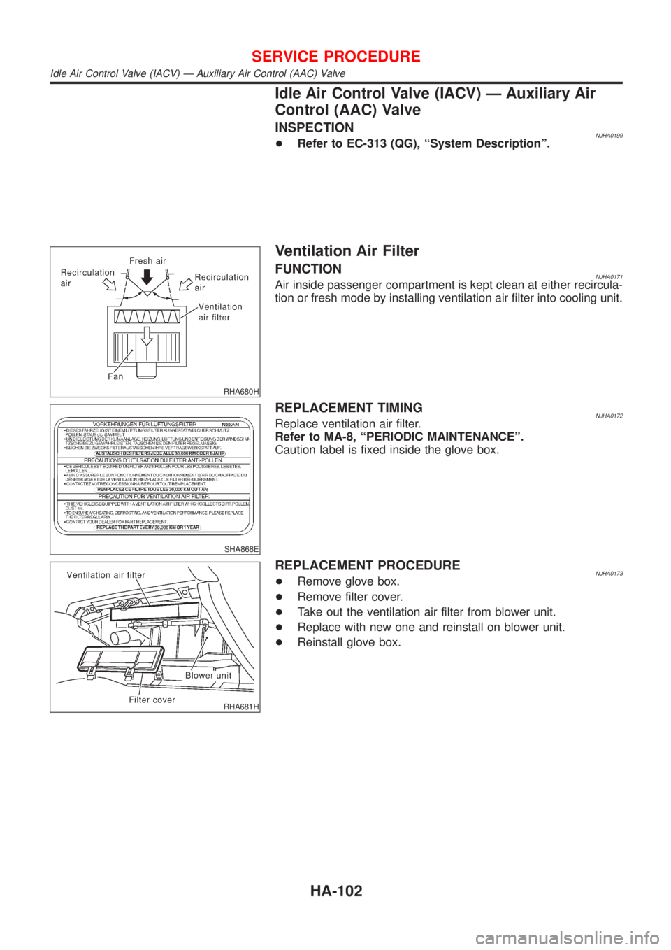
Idle Air Control Valve (IACV) Ð Auxiliary Air
Control (AAC) Valve
INSPECTIONNJHA0199+Refer to EC-313 (QG), ªSystem Descriptionº.
RHA680H
Ventilation Air Filter
FUNCTIONNJHA0171Air inside passenger compartment is kept clean at either recircula-
tion or fresh mode by installing ventilation air filter into cooling unit.
SHA868E
REPLACEMENT TIMINGNJHA0172Replace ventilation air filter.
Refer to MA-8, ªPERIODIC MAINTENANCEº.
Caution label is fixed inside the glove box.
RHA681H
REPLACEMENT PROCEDURENJHA0173+Remove glove box.
+Remove filter cover.
+Take out the ventilation air filter from blower unit.
+Replace with new one and reinstall on blower unit.
+Reinstall glove box.
SERVICE PROCEDURE
Idle Air Control Valve (IACV) Ð Auxiliary Air Control (AAC) Valve
HA-102
Page 2485 of 2493

Heated oxygen sensor (HO2S) heater
(rear) ............................................ EC-243, 389
Heated oxygen sensor (rear) ......... EC-214, 222,
229, 237, 383
Heated seat ............................................. EL-163
Height (Dimensions) ................................... GI-43
High clutch ............................................... AT-394
Hood ............................................................ BT-7
Horn ......................................................... EL-135
How to erase DTC for OBD system .. EC-68, 71,
522
I
IACV-AAC valve .............................. EC-313, 418
IATS - Wiring diagram .................... EC-160, 370
IGN/SG - Wiring diagram ........................ EC-452
ILL - Wiring diagram .................................. EL-72
INJECT - Wiring diagram ........................ EC-447
INT/L - Wiring diagram .............................. EL-87
IVC - Wiring diagram ...................... EC-331, 433
Identification plate ...................................... GI-40
Idle air control (IAC) system ........... EC-313, 418
Idle air control valve (IACV) ............ EC-313, 418
Idle speed ......................................... EC-41, 536
Ignition timing ............................................ EC-41
Illumination ................................................. EL-71
Injection nozzle ....................................... EC-509
Injector removal and installation ............... EC-39
Input shaft (FF M/T) ............... MT-36, 64, 93, 98
Instrument panel ........................................ BT-25
Intake air temperature sensor ......... EC-158, 369
Intake valve timing control solenoid
valve ............................................ EC-329, 432
Interior lamp on-off control ........................ EL-77
Interior lamp ............................................... EL-76
Interior ........................................................ BT-31
J
Jacking points ............................................ GI-45
Joint connector (J/C) ............................... EL-372
Junction box (J/B) .................................... EL-369
K
Keyless entry system - See Multi-remote control
system ..................................................... EL-220
Knock sensor (KS) .......................... EC-268, 269
Knuckle spindle ........................................... AX-5
L
LOAD - Wiring diagram .......................... EC-481
Length (Dimensions) .................................. GI-43
License lamp ............................................. EL-53Lifting points ............................................... GI-46
Line pressure solenoid valve ................... AT-230
Line pressure test (A/T) ............................. AT-82
Liquid gasket application ...................... EM-4, 76
Location of electrical units ....................... EL-319
Lock, door .................................................. BT-21
Low and reverse brake ............................ AT-406
Lubricant (R134a) A/C .............................. HA-86
Lubricants ................................................. MA-20
Lubrication circuit (engine) .................... LC-4, 26
M
M/T major overhaul ....................... MT-30, 54, 92
M/T removal and installation ..................... MT-23
MAFS - Wiring diagram .................. EC-154, 566
MAIN - Wiring diagram ................... EC-145, 560
MAJOR OVERHALL ................................ AT-349
MIL & Data link connectors circuit .......... EC-488
MIL/DL - Wiring diagram ................. EC-488, 701
MIRROR - Wiring diagram ...................... EL-167
Magnet clutch ............................................ HA-89
Mainshaft (M/T) .................... MT-39, 69, 93, 103
Malfunction indicator lamp (MIL) ...... EC-72, 523
Manual air conditioner - Wiring
diagram .................................................. HA-27
Manual transaxle number .......................... GI-42
Mass air flow sensor (MAFS) ......... EC-152, 566
Master cylinder (clutch) ............................. CL-11
Meter .......................................................... EL-89
Mirror defogger ........................................ EL-138
Mirror, door ................................................ BT-72
Misfire ...................................................... EC-262
Mode door control linkage
adjustment ............................................. HA-47
Model variation ........................................... GI-38
Molding - See Exterior ............................... BT-47
Multi-remote control system .................... EL-220
Multiport fuel injection (MFI) system ......... EC-29
Multiport fuel injection precautions ............... GI-6
N
NATS (Nissan Anti-theft System)
precautions ................................................... GI-3
NATS (Nissan Anti-theft System) ............ EL-234
NATS - Wiring diagram ............................ EL-237
NVH troubleshooting (AX) ........................... AX-3
NVH troubleshooting (BR) .......................... BR-6
NVH troubleshooting (MT) ........................ MT-13
NVH troubleshooting (ST) ........................... ST-5
NVH troubleshooting (SU) ........................ SU-16
NVH troubleshooting CL ............................. CL-4
NVIS (Nissan vehicle immobiliser sys-
tem) precautions ....................................... GI-3
Neutral position switch .................... EC-364, 441
ALPHABETICAL INDEX
IDX-5
Page 2486 of 2493

O
Oil pan (engine) .................................. EM-19, 88
Oil pressure (engine) ............................ LC-5, 27
Oil pump (A/T) ......................................... AT-371
Oil pump (engine) ................................. LC-5, 27
Oil pump regulator valve (engine) ......... LC-7, 29
Oil seal replacement (engine) .................. EM-31
On board diagnostic system ............. EC-57, 522
Operating cylinder (clutch) ........................ CL-14
Overdrive control switch .......................... AT-333
Overrun clutch .......................................... AT-399
P
PCV (positive crankcase ventilation) ....... EC-37,
508
PGC/V - Wiring diagram ................. EC-306, 413
PNP/SW - Wiring diagram ...... EC-366, 442, 696
POWER - Wiring diagram ......................... EL-12
PST/SW - Wiring diagram ....................... EC-471
Park/Neutral position switch ... EC-364, 441, 696
Park/neutral position switch (A/T) ............ AT-181
Park/neutral position switch (M/T) ............ MT-21
Parking brake control ................................ BR-47
Parking lamp .............................................. EL-53
Piston assembly ............................... EM-60, 154
Piston pin inspection ........................ EM-54, 144
Piston ring inspection ....................... EM-54, 144
Piston to bore clearance .................. EM-56, 146
Power antenna ........................................ EL-162
Power door lock ....................................... EL-177
Power door mirror .................................... EL-167
Power steering fluid level ............................ ST-7
Power steering gear .................................. ST-15
Power steering hydraulic pressure .............. ST-9
Power steering oil pressure switch ......... EC-470
Power steering system bleeding ................. ST-8
Power supply routing ................................... EL-9
Power window ......................................... EL-169
Precautions (General) .................................. GI-4
Pressure plate - See Clutch cover ............ CL-22
Priming pump .................................. EC-520, 536
Q
Quick-glow system .................................. EC-677
R
RR02 - Wiring diagram .. EC-217, 225, 232, 239,
384
RR02/H - Wiring diagram ............... EC-245, 390
Radiator ............................................... LC-16, 41
Radio - See Audio ................................... EL-149
Rear air spoiler .......................................... BT-47Rear axle (disc brake type) ....................... AX-24
Rear axle ................................................... AX-22
Rear bumper .............................................. BT-10
Rear combination lamp removal and
installation .............................................. BT-47
Rear disc brake .................................. BR-35, 43
Rear door ................................................... BT-16
Rear drum brake ....................................... BR-31
Rear heated oxygen sensor (HO2S)
heater .......................................... EC-243, 389
Rear heated oxygen sensor (HO2S) ..... EC-214,
222, 229, 237, 383
Rear seat belt ............................................ RS-11
Rear seat ................................................... BT-59
Rear suspension ....................................... SU-16
Rear window defogger ............................ EL-138
Rear window .............................................. BT-68
Refrigerant connection precaution .............. HA-3
Refrigerant general precaution ................... HA-2
Refrigerant lines ........................................ HA-97
Refrigeration cycle .................................... HA-13
Release bearing (clutch) ..................... CL-17, 20
Removal and installation (A/T) ................ AT-346
Reverse clutch ......................................... AT-390
Reverse idler shaft (M/T) .............. MT-30, 54, 93
Reverse lamp switch (M/T) - See
Back-up lamp switch (M/T) ................... MT-21
Reverse main gear (M/T) ............. MT-31, 55, 93
Road wheel size ......................................... GI-43
Roof trim .................................................... BT-43
Room lamp - See Interior lamp ................. EL-76
S
S/LOCK - Wiring diagram ................ EL-180, 200
S/SIG - Wiring diagram ........................... EC-461
SAE J1930 terminology list ........................ GI-50
SHIFT - Wiring diagram ........................... AT-336
SROOF - Wiring diagram ........................ EL-165
SRS - See Supplemental Restraint
System ................................................... RS-20
START - Wiring diagram ........................... SC-14
STOP/L - Wiring diagram .......................... EL-56
Seal - See Exterior .................................... BT-47
Seat belt pre-tensioner disposal ............... RS-35
Seat belt pre-tensioner ............................... RS-3
Seat belt, front ............................................ RS-5
Seat belt, rear ............................................ RS-11
Seat, front .................................................. BT-56
Seat, rear ................................................... BT-59
Self-diagnostic results ....................... EC-72, 523
Shift control components (M/T) .... MT-32, 56, 94
Shift fork (M/T) .............................. MT-32, 56, 94
Shift lever .................................................. MT-29
Shift lock system ...................................... AT-335
Shift schedule .......................................... AT-449
Shift solenoid valve A (A/T) ..... AT-202, 207, 220
Shift solenoid valve B (A/T) ............. AT-202, 207
Shock absorber (front) .............................. SU-10
ALPHABETICAL INDEX
IDX-6