Page 2061 of 2493
RHA065DH
Compressor
REMOVAL AND INSTALLATIONNJHA0161
RHA803H
SERVICE PROCEDURE
Maintenance of Lubricant Quantity in Compressor (Cont'd)
HA-89
Page 2071 of 2493

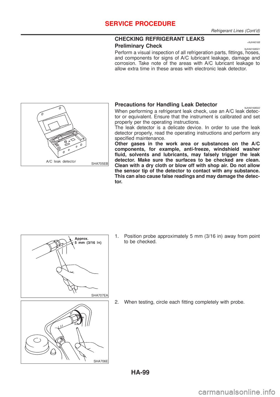
CHECKING REFRIGERANT LEAKS=NJHA0168Preliminary CheckNJHA0168S01Perform a visual inspection of all refrigeration parts, fittings, hoses,
and components for signs of A/C lubricant leakage, damage and
corrosion. Take note of the areas with A/C lubricant leakage to
allow extra time in these areas with electronic leak detector.
SHA705EB
Precautions for Handling Leak DetectorNJHA0168S02When performing a refrigerant leak check, use an A/C leak detec-
tor or equivalent. Ensure that the instrument is calibrated and set
properly per the operating instructions.
The leak detector is a delicate device. In order to use the leak
detector properly, read the operating instructions and perform any
specified maintenance.
Other gases in the work area or substances on the A/C
components, for example, anti-freeze, windshield washer
fluid, solvents and lubricants, may falsely trigger the leak
detector. Make sure the surfaces to be checked are clean.
Clean with a dry cloth or blow off with shop air. Do not allow
the sensor tip of the detector to contact with any substance.
This can also cause false readings and may damage the detec-
tor.
SHA707EA
1. Position probe approximately 5 mm (3/16 in) away from point
to be checked.
SHA706E
2. When testing, circle each fitting completely with probe.
SERVICE PROCEDURE
Refrigerant Lines (Cont'd)
HA-99
Page 2074 of 2493
Idle Air Control Valve (IACV) Ð Auxiliary Air
Control (AAC) Valve
INSPECTIONNJHA0199+Refer to EC-313 (QG), ªSystem Descriptionº.
RHA680H
Ventilation Air Filter
FUNCTIONNJHA0171Air inside passenger compartment is kept clean at either recircula-
tion or fresh mode by installing ventilation air filter into cooling unit.
SHA868E
REPLACEMENT TIMINGNJHA0172Replace ventilation air filter.
Refer to MA-8, ªPERIODIC MAINTENANCEº.
Caution label is fixed inside the glove box.
RHA681H
REPLACEMENT PROCEDURENJHA0173+Remove glove box.
+Remove filter cover.
+Take out the ventilation air filter from blower unit.
+Replace with new one and reinstall on blower unit.
+Reinstall glove box.
SERVICE PROCEDURE
Idle Air Control Valve (IACV) Ð Auxiliary Air Control (AAC) Valve
HA-102
Page 2078 of 2493

Supplemental Restraint System (SRS) ªAIR
BAGº and ªSEAT BELT PRE-TENSIONERº
NJSC0001The Supplemental Restraint System such as ªAIR BAGº and ªSEAT BELT PRE-TENSIONERº used along with
a seat belt, helps to reduce the risk or severity of injury to the driver and front passenger for certain types of
collision. The SRS system composition which is available to NISSAN MODEL N16 is as follows (The compo-
sition varies according to the destination and optional equipment.):
+For a frontal collision
The Supplemental Restraint System consists of driver air bag module (located in the center of the steer-
ing wheel), front passenger air bag module (located on the instrument panel on passenger side), front seat
belt pre-tensioners, a diagnosis sensor unit, warning lamp, wiring harness and spiral cable.
+For a side collision
The Supplemental Restraint System consists of front side air bag module (located in the outer side of front
seat), side air bag (satellite) sensor, diagnosis sensor unit (one of components of air bags for a frontal
collision), wiring harness, warning lamp (one of components of air bags for a frontal collision).
Information necessary to service the system safely is included in theRS sectionof this Service Manual.
WARNING:
+To avoid rendering the SRS inoperative, which could increase the risk of personal injury or death
in the event of a collision which would result in air bag inflation, all maintenance should be per-
formed by an authorized NISSAN dealer.
+Improper maintenance, including incorrect removal and installation of the SRS, can lead to per-
sonal injury caused by unintentional activation of the system. For removal of Spiral Cable and Air
Bag Module, see the RS section.
+Do not use electrical test equipment on any circuit related to the SRS unless instructed to in this
Service Manual. SRS wiring harnesses can be identified by yellow harness connector.
Wiring Diagrams and Trouble DiagnosesNJSC0002When you read wiring diagrams, refer to the following:
+GI-12, ªHOW TO READ WIRING DIAGRAMSº
+EL-10, ªPOWER SUPPLY ROUTINGº for power distribution circuit
When you perform trouble diagnoses, refer to the following:
+GI-32, ªHOW TO FOLLOW TEST GROUPS IN TROUBLE DIAGNOSESº
+GI-21, ªHOW TO PERFORM EFFICIENT DIAGNOSIS FOR AN ELECTRICAL INCIDENTº
PRECAUTIONS
Supplemental Restraint System (SRS) ªAIR BAGº and ªSEAT BELT PRE-TENSIONERº
SC-2
Page 2079 of 2493

How to Handle BatteryNJSC0003CAUTION:
If it becomes necessary to start the engine with a booster
battery and jumper cables,
1) Use a 12-volt booster battery.
2) After connecting battery cables, ensure that they are
tightly clamped to battery terminals for good contact.
3) Never add distilled water through the hole used to check
specific gravity.
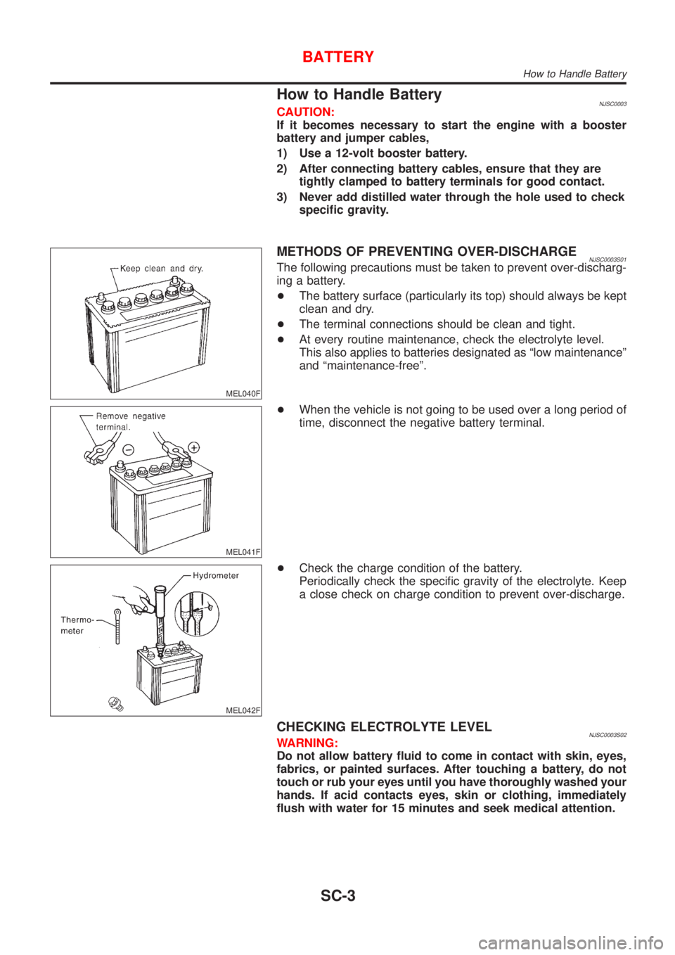
MEL040F
METHODS OF PREVENTING OVER-DISCHARGENJSC0003S01The following precautions must be taken to prevent over-discharg-
ing a battery.
+The battery surface (particularly its top) should always be kept
clean and dry.
+The terminal connections should be clean and tight.
+At every routine maintenance, check the electrolyte level.
This also applies to batteries designated as ªlow maintenanceº
and ªmaintenance-freeº.
MEL041F
+When the vehicle is not going to be used over a long period of
time, disconnect the negative battery terminal.
MEL042F
+Check the charge condition of the battery.
Periodically check the specific gravity of the electrolyte. Keep
a close check on charge condition to prevent over-discharge.
CHECKING ELECTROLYTE LEVELNJSC0003S02WARNING:
Do not allow battery fluid to come in contact with skin, eyes,
fabrics, or painted surfaces. After touching a battery, do not
touch or rub your eyes until you have thoroughly washed your
hands. If acid contacts eyes, skin or clothing, immediately
flush with water for 15 minutes and seek medical attention.
BATTERY
How to Handle Battery
SC-3
Page 2116 of 2493

Supplemental Restraint System (SRS) ªAIR
BAGº and ªSEAT BELT PRE-TENSIONERº
NJEL0001The Supplemental Restraint System such as ªAIR BAGº and ªSEAT BELT PRE-TENSIONERº used along with
a seat belt, helps to reduce the risk or severity of injury to the driver and front passenger for certain types of
collision. The SRS system composition which is available to NISSAN MODEL N16 is as follows (The compo-
sition varies according to the destination and optional equipment.):
+For a frontal collision
The Supplemental Restraint System consists of driver air bag module (located in the center of the steer-
ing wheel), front passenger air bag module (located on the instrument panel on passenger side), front seat
belt pre-tensioners, a diagnosis sensor unit, warning lamp, wiring harness and spiral cable.
+For a side collision
The Supplemental Restraint System consists of front side air bag module (located in the outer side of front
seat), side air bag (satellite) sensor, diagnosis sensor unit (one of components of air bags for a frontal
collision), wiring harness, warning lamp (one of components of air bags for a frontal collision).
Information necessary to service the system safely is included in theRS sectionof this Service Manual.
WARNING:
+To avoid rendering the SRS inoperative, which could increase the risk of personal injury or death
in the event of a collision which would result in air bag inflation, all maintenance should be per-
formed by an authorized NISSAN dealer.
+Improper maintenance, including incorrect removal and installation of the SRS, can lead to per-
sonal injury caused by unintentional activation of the system. For removal of Spiral Cable and Air
Bag Module, see the RS section.
+Do not use electrical test equipment on any circuit related to the SRS unless instructed to in this
Service Manual. SRS wiring harnesses can be identified by yellow harness connector.
Wiring Diagrams and Trouble DiagnosisNJEL0002When you read wiring diagrams, refer to the following:
+Refer to GI-12, ªHOW TO READ WIRING DIAGRAMSº
+Refer to EL-10, ªPOWER SUPPLY ROUTINGº for power distribution circuit
When you perform trouble diagnosis, refer to the following:
+Refer to GI-32, ªHOW TO FOLLOW TEST GROUPS IN TROUBLE DIAGNOSESº
+Refer to GI-21, ªHOW TO PERFORM EFFICIENT DIAGNOSIS FOR AN ELECTRICAL INCIDENTº
Check for any Service bulletins before servicing the vehicle.
PRECAUTIONS
Supplemental Restraint System (SRS) ªAIR BAGº and ªSEAT BELT PRE-TENSIONERº
EL-4