2001 NISSAN ALMERA N16 maintenance
[x] Cancel search: maintenancePage 72 of 2493
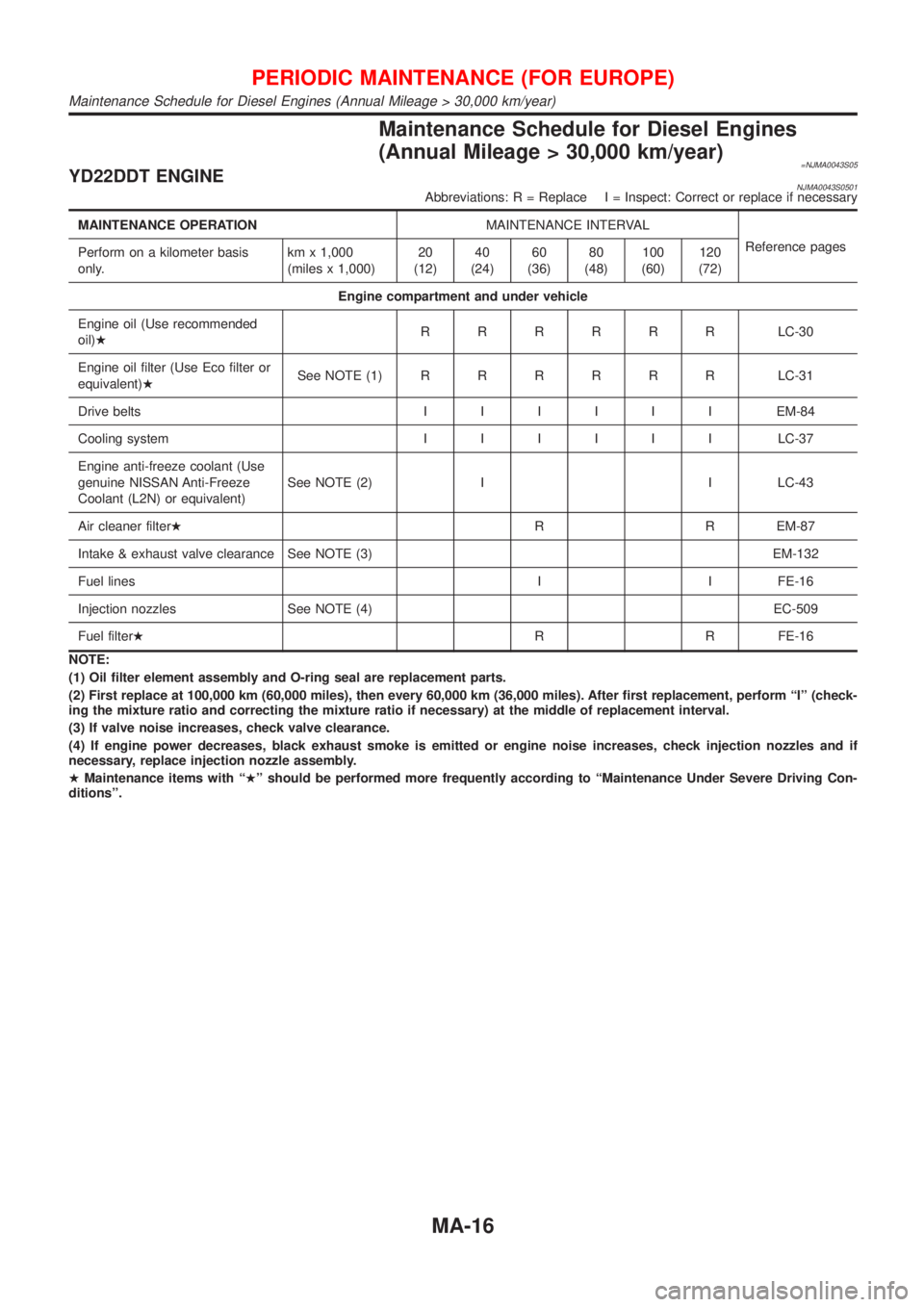
Maintenance Schedule for Diesel Engines
(Annual Mileage > 30,000 km/year)
=NJMA0043S05YD22DDT ENGINENJMA0043S0501Abbreviations: R = Replace I = Inspect: Correct or replace if necessary
MAINTENANCE OPERATIONMAINTENANCE INTERVAL
Reference pages
Perform on a kilometer basis
only.km x 1,000
(miles x 1,000)20
(12)40
(24)60
(36)80
(48)100
(60)120
(72)
Engine compartment and under vehicle
Engine oil (Use recommended
oil)HRRRRRRLC-30
Engine oil filter (Use Eco filter or
equivalent)HSee NOTE (1)RRRRRRLC-31
Drive beltsIIIIIIEM-84
Cooling systemIIIIIILC-37
Engine anti-freeze coolant (Use
genuine NISSAN Anti-Freeze
Coolant (L2N) or equivalent)See NOTE (2) I I LC-43
Air cleaner filterHR R EM-87
Intake & exhaust valve clearance See NOTE (3) EM-132
Fuel lines I I FE-16
Injection nozzles See NOTE (4) EC-509
Fuel filterHR R FE-16
NOTE:
(1) Oil filter element assembly and O-ring seal are replacement parts.
(2) First replace at 100,000 km (60,000 miles), then every 60,000 km (36,000 miles). After first replacement, perform ªIº (check-
ing the mixture ratio and correcting the mixture ratio if necessary) at the middle of replacement interval.
(3) If valve noise increases, check valve clearance.
(4) If engine power decreases, black exhaust smoke is emitted or engine noise increases, check injection nozzles and if
necessary, replace injection nozzle assembly.
HMaintenance items with ªHº should be performed more frequently according to ªMaintenance Under Severe Driving Con-
ditionsº.
PERIODIC MAINTENANCE (FOR EUROPE)
Maintenance Schedule for Diesel Engines (Annual Mileage > 30,000 km/year)
MA-16
Page 73 of 2493
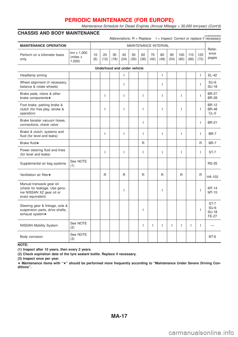
CHASSISAN DBOD YMAINTENANCE
MAINTENANC EOPER ATION MAINTENANCEINTE RVAL
Maintenance Schedule for Diesel Engines (Annual Mileage > 30,000 km/year) (Cont'd)
Page 74 of 2493

Maintenance Under Severe Driving Conditions
(Annual Driving Distance > 30,000 km/year)
=NJMA0043S06The maintenance intervals shown on the preceding pages are for normal operating conditions. If the vehicle
is mainly operated under severe driving conditions as shown below, more frequent maintenance must be per-
formed on the following items as shown in the table.
A Ð Driving under dusty conditions
B Ð Driving repeatedly short distances
C Ð Towing a trailer or caravan
D Ð Extensive idling
E Ð Driving in extremely adverse weather conditions or in areas where ambient temperatures are either
extremely low or extremely high
F Ð Driving in high humidity areas or in mountainous areas
G Ð Driving in areas using salt or other corrosive materials
H Ð Driving on rough and/or muddy roads or in the desert
I Ð Driving with frequent use of braking or in mountainous areas
J Ð Frequent off road use or driving in water
K Ð Sustained high speed driving
L Ð For models without Euro-OBD system
Driving conditionMaintenance
itemMaintenance
operationMaintenance interval
ABCD........Engine oil & engine oil filter
Petrol models Replace Every 7,500 km (4,500 miles)
Diesel models Replace Every 10,000 km (6,000 miles)
A...........Air cleaner filter
Petrol models Replace Every 30,000 km (18,000 miles)
Diesel models Replace Every 30,000 km (18,000 miles)
A...E.......Fuel filter
Diesel models Replace Every 30,000 km (18,000 miles)
...........LHeated Oxygen Sensor 1 (Front)
Petrol models Inspect Every 60,000 km (36,000 miles)
...........LHeated Oxygen Sensor 2 (Rear)
Petrol models Inspect Every 60,000 km (36,000 miles)
A...........Ventilation air filter
Petrol models Replace Every 15,000 km (9,000 miles)
Diesel models Replace Every 10,000 km (6,000 miles)
.....F......Brake fluid
Petrol models Replace Every 30,000 km (18,000 miles)
Diesel models Replace Every 30,000 km (18,000 miles)
..C....H....Automatic transaxle fluid
Petrol models Replace Every 60,000 km (36,000 miles)
A.C...GHI...Brake pads, rotors & other brake system components
Petrol models Inspect Every 15,000 km (9,000 miles)
Diesel models Inspect Every 10,000 km (6,000 miles)
PERIODIC MAINTENANCE (FOR EUROPE)
Maintenance Under Severe Driving Conditions (Annual Driving Distance > 30,000 km/year)
MA-18
Page 75 of 2493
Driving conditionMaintenance
itemMaintenance
operationMaintenance interval
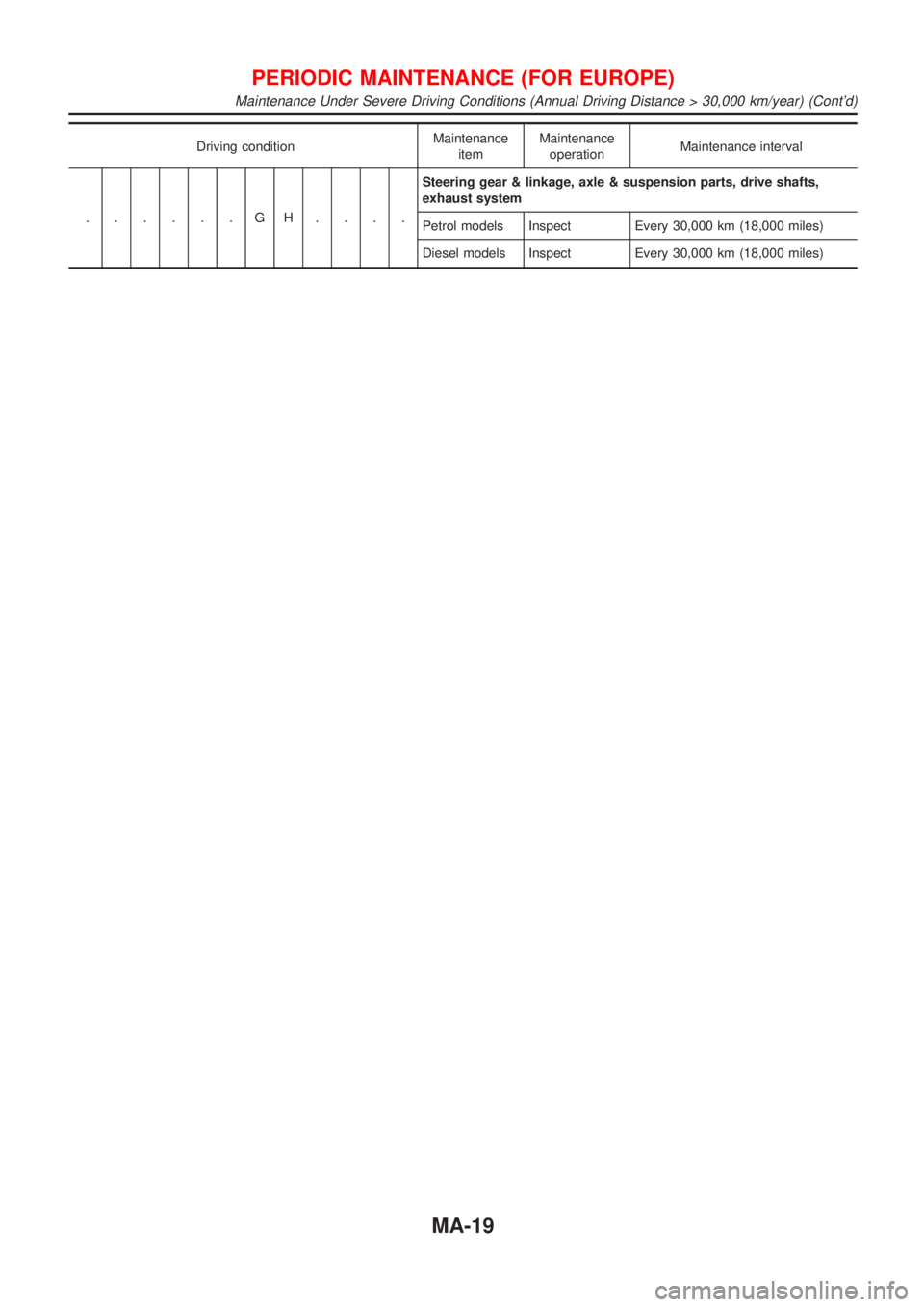
......GH....Steering gear & linkage, axle & suspension parts, drive shafts,
exhaust system
Petrol models Inspect Every 30,000 km (18,000 miles)
Diesel models Inspect Every 30,000 km (18,000 miles)
PERIODIC MAINTENANCE (FOR EUROPE)
Maintenance Under Severe Driving Conditions (Annual Driving Distance > 30,000 km/year) (Cont'd)
MA-19
Page 312 of 2493

Supplemental Restraint System (SRS) ªAIR
BAGº and ªSEAT BELT PRE-TENSIONERº
NJEC0002The Supplemental Restraint System such as ªAIR BAGº and ªSEAT BELT PRE-TENSIONERº used along with
a seat belt, helps to reduce the risk or severity of injury to the driver and front passenger for certain types of
collision. The SRS system composition which is available to NISSAN MODEL N16 is as follows (The compo-
sition varies according to the destination and optional equipment.):
+For a frontal collision
The Supplemental Restraint System consists of driver air bag module (located in the center of the steer-
ing wheel), front passenger air bag module (located on the instrument panel on passenger side), front seat
belt pre-tensioners, a diagnoses sensor unit, warning lamp, wiring harness and spiral cable.
+For a side collision
The Supplemental Restraint System consists of front side air bag module (located in the outer side of front
seat), side air bag (satellite) sensor, diagnoses sensor unit (one of components of air bags for a frontal
collision), wiring harness, warning lamp (one of components of air bags for a frontal collision).
Information necessary to service the system safely is included in theRS sectionof this Service Manual.
WARNING:
+To avoid rendering the SRS inoperative, which could increase the risk of personal injury or death
in the event of a collision which would result in air bag inflation, all maintenance should be per-
formed by an authorized NISSAN dealer.
+Improper maintenance, including incorrect removal and installation of the SRS, can lead to per-
sonal injury caused by unintentional activation of the system. For removal of Spiral Cable and Air
Bag Module, see the RS section.
+Do not use electrical test equipment on any circuit related to the SRS unless instructed to in this
Service Manual. SRS wiring harness can be identified by yellow harness connector.
Precautions for On Board Diagnostic (OBD)
System of Engine and A/T
NJEC0003The ECM has an on board diagnostic system. It will light up the malfunction indicator (MI) to warn the driver
of a malfunction causing emission deterioration.
CAUTION:
+Be sure to turn the ignition switch ªOFFº and disconnect the negative battery terminal before any
repair or inspection work. The open/short circuit of related switches, sensors, solenoid valves, etc.
will cause the MI to light up.
+Be sure to connect and lock the connectors securely after work. A loose (unlocked) connector will
cause the MI to light up due to the open circuit. (Be sure the connector is free from water, grease,
dirt, bent terminals, etc.)
+Certain systems and components, especially those related to OBD, may use a new style slide-
locking type harness connector.
For description and how to disconnect, refer to EL section, ªDescriptionº, ªHARNESS CONNEC-
TORº.
+Be sure to route and secure the harnesses properly after work. The interference of the harness with
a bracket, etc. may cause the MI to light up due to the short circuit.
+Be sure to connect rubber tubes properly after work. A misconnected or disconnected rubber tube
may cause the MI to light up due to the malfunction of fuel injection system, etc.
+Be sure to erase the unnecessary malfunction information (repairs completed) from the ECM and
TCM (Transmission Control Module) before returning the vehicle to the customer.
PRECAUTIONSQG
Supplemental Restraint System (SRS) ªAIR BAGº and ªSEAT BELT PRE-TENSIONERº
EC-16
Page 354 of 2493
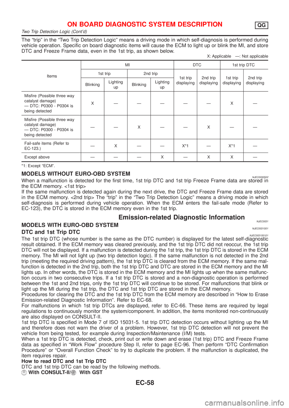
The ªtripº in the ªTwo Trip Detection Logicº means a driving mode in which self-diagnosis is performed during
vehicle operation. Specific on board diagnostic items will cause the ECM to light up or blink the MI, and store
DTC and Freeze Frame data, even in the 1st trip, as shown below.
X: Applicable Ð: Not applicable
ItemsMI DTC 1st trip DTC
1st trip 2nd trip
1st trip
displaying2nd trip
displaying1st trip
displaying2nd trip
displaying
BlinkingLighting
upBlinkingLighting
up
Misfire (Possible three way
catalyst damage)
Ð DTC: P0300 - P0304 is
being detectedX ÐÐÐÐÐ X Ð
Misfire (Possible three way
catalyst damage)
Ð DTC: P0300 - P0304 is
being detectedÐÐXÐÐXÐÐ
Fail-safe items (Refer to
EC-123.)Ð X Ð Ð X*1 Ð X*1 Ð
Except above Ð ÐÐXÐX XÐ
*1: Except ªECMº.
MODELS WITHOUT EURO-OBD SYSTEMNJEC0030S02When a malfunction is detected for the first time, 1st trip DTC and 1st trip Freeze Frame data are stored in
the ECM memory. <1st trip>
If the same malfunction is detected again during the next drive, the DTC and Freeze Frame data are stored
in the ECM memory. <2nd trip> The ªtripº in the ªTwo Trip Detection Logicº means a driving mode in which
self-diagnosis is performed during vehicle operation. When the ECM enters the fail-safe mode (Refer to
EC-123), the DTC is stored in the ECM memory even in the 1st trip.
Emission-related Diagnostic InformationNJEC0031MODELS WITH EURO-OBD SYSTEMNJEC0031S01DTC and 1st Trip DTCNJEC0031S0101The 1st trip DTC (whose number is the same as the DTC number) is displayed for the latest self-diagnostic
result obtained. If the ECM memory was cleared previously, and the 1st trip DTC did not reoccur, the 1st trip
DTC will not be displayed. If a malfunction is detected during the 1st trip, the 1st trip DTC is stored in the ECM
memory. The MI will not light up (two trip detection logic). If the same malfunction is not detected in the 2nd
trip (meeting the required driving pattern), the 1st trip DTC is cleared from the ECM memory. If the same mal-
function is detected in the 2nd trip, both the 1st trip DTC and DTC are stored in the ECM memory and the MI
lights up. In other words, the DTC is stored in the ECM memory and the MI lights up when the same malfunc-
tion occurs in two consecutive trips. If a 1st trip DTC is stored and a non-diagnostic operation is performed
between the 1st and 2nd trips, only the 1st trip DTC will continue to be stored. For malfunctions that blink or
light up the MI during the 1st trip, the DTC and 1st trip DTC are stored in the ECM memory.
Procedures for clearing the DTC and the 1st trip DTC from the ECM memory are described in ªHow to Erase
Emission-related Diagnostic Informationº. Refer to EC-68.
For malfunctions in which 1st trip DTCs are displayed, refer to EC-66. These items are required by legal
regulations to continuously monitor the system/component. In addition, the items monitored non-continuously
are also displayed on CONSULT-II.
1st trip DTC is specified in Mode 7 of ISO 15031-5. 1st trip DTC detection occurs without lighting up the MI
and therefore does not warn the driver of a problem. However, 1st trip DTC detection will not prevent the
vehicle from being tested, for example during Inspection/Maintenance (I/M) tests.
When a 1st trip DTC is detected, check, print out or write down and erase (1st trip) DTC and Freeze Frame
data as specified in ªWork Flowº procedure Step II, refer to page EC-96. Then perform ªDTC Confirmation
Procedureº or ªOverall Function Checkº to try to duplicate the problem. If the malfunction is duplicated, the
item requires repair.
How to read DTC and 1st Trip DTC
DTC and 1st trip DTC can be read by the following methods.
With CONSULT-II/With GST
ON BOARD DIAGNOSTIC SYSTEM DESCRIPTIONQG
Two Trip Detection Logic (Cont'd)
EC-58
Page 356 of 2493
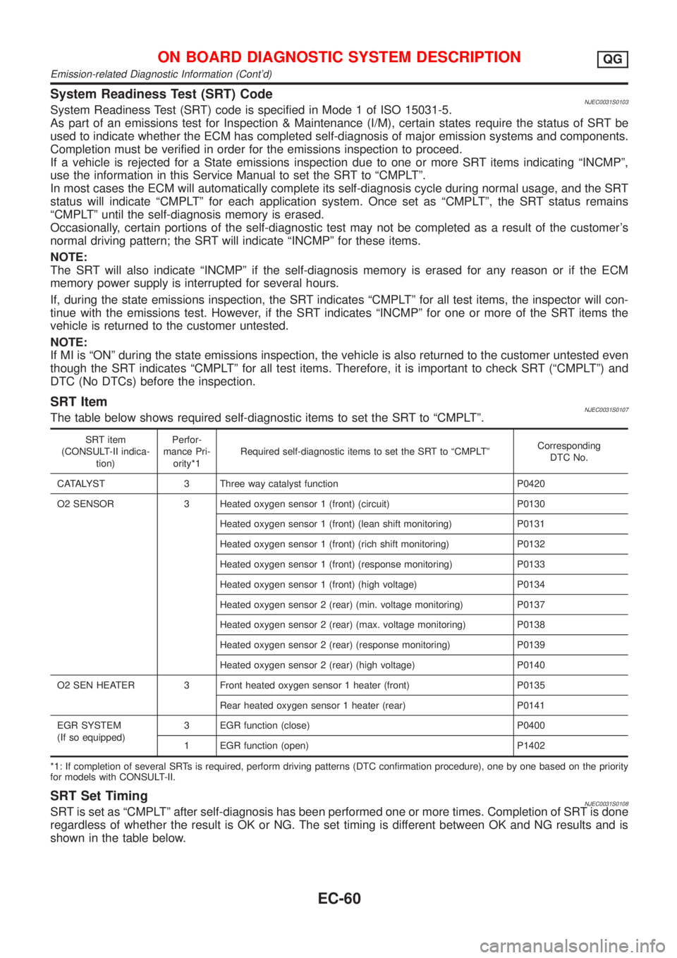
System Readiness Test (SRT) CodeNJEC0031S0103System Readiness Test (SRT) code is specified in Mode 1 of ISO 15031-5.
As part of an emissions test for Inspection & Maintenance (I/M), certain states require the status of SRT be
used to indicate whether the ECM has completed self-diagnosis of major emission systems and components.
Completion must be verified in order for the emissions inspection to proceed.
If a vehicle is rejected for a State emissions inspection due to one or more SRT items indicating ªINCMPº,
use the information in this Service Manual to set the SRT to ªCMPLTº.
In most cases the ECM will automatically complete its self-diagnosis cycle during normal usage, and the SRT
status will indicate ªCMPLTº for each application system. Once set as ªCMPLTº, the SRT status remains
ªCMPLTº until the self-diagnosis memory is erased.
Occasionally, certain portions of the self-diagnostic test may not be completed as a result of the customer's
normal driving pattern; the SRT will indicate ªINCMPº for these items.
NOTE:
The SRT will also indicate ªINCMPº if the self-diagnosis memory is erased for any reason or if the ECM
memory power supply is interrupted for several hours.
If, during the state emissions inspection, the SRT indicates ªCMPLTº for all test items, the inspector will con-
tinue with the emissions test. However, if the SRT indicates ªINCMPº for one or more of the SRT items the
vehicle is returned to the customer untested.
NOTE:
If MI is ªONº during the state emissions inspection, the vehicle is also returned to the customer untested even
though the SRT indicates ªCMPLTº for all test items. Therefore, it is important to check SRT (ªCMPLTº) and
DTC (No DTCs) before the inspection.
SRT ItemNJEC0031S0107The table below shows required self-diagnostic items to set the SRT to ªCMPLTº.
SRT item
(CONSULT-II indica-
tion)Perfor-
mance Pri-
ority*1Required self-diagnostic items to set the SRT to ªCMPLTºCorresponding
DTC No.
CATALYST 3 Three way catalyst function P0420
O2 SENSOR 3 Heated oxygen sensor 1 (front) (circuit) P0130
Heated oxygen sensor 1 (front) (lean shift monitoring) P0131
Heated oxygen sensor 1 (front) (rich shift monitoring) P0132
Heated oxygen sensor 1 (front) (response monitoring) P0133
Heated oxygen sensor 1 (front) (high voltage) P0134
Heated oxygen sensor 2 (rear) (min. voltage monitoring) P0137
Heated oxygen sensor 2 (rear) (max. voltage monitoring) P0138
Heated oxygen sensor 2 (rear) (response monitoring) P0139
Heated oxygen sensor 2 (rear) (high voltage) P0140
O2 SEN HEATER 3 Front heated oxygen sensor 1 heater (front) P0135
Rear heated oxygen sensor 1 heater (rear) P0141
EGR SYSTEM
(If so equipped)3 EGR function (close) P0400
1 EGR function (open) P1402
*1: If completion of several SRTs is required, perform driving patterns (DTC confirmation procedure), one by one based on the priority
for models with CONSULT-II.
SRT Set TimingNJEC0031S0108SRT is set as ªCMPLTº after self-diagnosis has been performed one or more times. Completion of SRT is done
regardless of whether the result is OK or NG. The set timing is different between OK and NG results and is
shown in the table below.
ON BOARD DIAGNOSTIC SYSTEM DESCRIPTIONQG
Emission-related Diagnostic Information (Cont'd)
EC-60
Page 394 of 2493

Basic InspectionNJEC1785MODELS WITH THROTTLE POSITION SWITCHNJEC1785S01Precaution:
Perform Basic Inspection without electrical or mechanical
loads applied;
+Headlamp switch is OFF,
On vehicle equipped with daytime light systems, set lighting
switch to the 1st position to light only small lamps.
+Air conditioner switch is OFF,
+Rear window defogger switch is OFF,
+Steering wheel is in the straight-ahead position, etc.
1 INSPECTION START
1. Check service records for any recent repairs that may indicate a related problem, or a current need for scheduled
maintenance.
2. Open engine hood and check the following:
+Harness connectors for improper connections
+Vacuum hoses for splits, kinks and improper connections
+Wiring for improper connections, pinches and cuts
+Air cleaner clogging
+Hoses and ducts for leaks
SEF983U
©GO TO 2.
2 CHECK THROTTLE OPENER OPERATION-I
Confirm that there is a clearance between throttle drum and stopper.
SEF850Y
OK or NG
OK©GO TO 4.
NG©GO TO 3.
TROUBLE DIAGNOSIS Ð BASIC INSPECTIONQG
Basic Inspection
EC-98