2001 NISSAN ALMERA N16 maintenance
[x] Cancel search: maintenancePage 409 of 2493

35 CHECK IGNITION TIMING AGAIN
Check ignition timing again. Refer to Test No. 31.
OK or NG
OK©GO TO 37.
NG©GO TO 36.
36 CHECK TIMING CHAIN INSTALLATION
Check timing chain installation. Refer to EM-27, ªInstallationº.
OK or NG
OK©GO TO 34.
NG©1. Repair the timing chain installation.
2. GO TO 32.
37 ERASE UNNECESSARY DTC
After this inspection, unnecessary DTC No. might be displayed.
Erase the stored memory in ECM and TCM (Transmission control module).
Refer to ªHow to Erase Emission-Related Diagnostic Informationº, EC-68 or EC-75 and AT-50, ªHOW TO ERASE DTCº.
OK or NG
©INSPECTION END
MODELS WITHOUT THROTTLE POSITION SWITCHNJEC1785S02Precaution:
Perform Basic Inspection without electrical or mechanical
loads applied;
+Headlamp switch is OFF,
On vehicle equipped with daytime light system, set lighting
switch to the 1st position to light only small lamps.
+Air conditioner switch is OFF,
+Rear window defogger switch is OFF,
+Steering wheel is in the straight-ahead position, etc.
1 INSPECTION START
1. Check service records for any recent repairs that may indicate a related problem, or a current need for scheduled
maintenance.
2. Open engine hood and check the following:
+Harness connectors for improper connections
+Vacuum hoses for splits, kinks and improper connections
+Wiring for improper connections, pinches and cuts
+Air cleaner clogging
+Hoses and ducts for leaks
SEF983U
©GO TO 2.
TROUBLE DIAGNOSIS Ð BASIC INSPECTIONQG
Basic Inspection (Cont'd)
EC-113
Page 548 of 2493

4 CHECK FUEL PRESSURE
1. Release fuel pressure to zero.
Refer to EC-38.
2. Install fuel pressure gauge and check fuel pressure.
At idling:
When fuel pressure regulator valve vacuum hose is connected.
235 kPa (2.35 bar, 2.4 kg/cm
2, 34 psi)
When fuel pressure regulator valve vacuum hose is disconnected.
294 kPa (2.94 bar, 3.0 kg/cm
2, 43 psi)
OK or NG
OK©GO TO 6.
NG©GO TO 5.
5 DETECT MALFUNCTIONING PART
Check the following.
+Fuel pump and circuit (Refer to EC-464.)
+Fuel pressure regulator (Refer to EC-39.)
+Fuel lines (Refer to ªENGINE MAINTENANCEº in MA section.)
+Fuel filter for clogging
©Repair or replace.
6 CHECK MASS AIR FLOW SENSOR
With CONSULT-II
Check ªMASS AIR FLOWº in ªDATA MONITORº mode with CONSULT-II.
at idling: 1.0 - 4.0 g´m/sec
at 2,500 rpm: 5.0 - 10.0 g´m/sec
With GST
Check mass air flow sensor signal in MODE 1 with GST.
at idling: 1.0 - 4.0 g´m/sec
at 2,500 rpm: 5.0 - 10.0 g´m/sec
OK or NG
OK©GO TO 7.
NG©Check connectors for rusted terminals or loose connections in the mass air flow sensor
circuit or engine grounds. Refer to EC-152.
DTC P0171 FUEL INJECTION SYSTEM FUNCTION (LEAN SIDE)QG
Diagnostic Procedure (Cont'd)
EC-252
Page 790 of 2493

Supplemental Restraint System (SRS) ªAIR
BAGº and ªSEAT BELT PRE-TENSIONERº
NJEC0601The Supplemental Restraint System such as ªAIR BAGº and ªSEAT BELT PRE-TENSIONERº used along with
a seat belt, helps to reduce the risk or severity of injury to the driver and front passenger for certain types of
collision. The SRS system composition which is available to NISSAN MODEL N16 is as follows (The compo-
sition varies according to the destination and optional equipment.):
+For a frontal collision
The Supplemental Restraint System consists of driver air bag module (located in the center of the steer-
ing wheel), front passenger air bag module (located on the instrument panel on passenger side), front seat
belt pre-tensioners, a diagnosis sensor unit, warning lamp, wiring harness and spiral cable.
+For a side collision
The Supplemental Restraint System consists of front side air bag module (located in the outer side of front
seat), side air bag (satellite) sensor, diagnosis sensor unit (one of components of air bags for a frontal
collision), wiring harness, warning lamp (one of components of air bags for a frontal collision).
Information necessary to service the system safely is included in theRS sectionof this Service Manual.
WARNING:
+To avoid rendering the SRS inoperative, which could increase the risk of personal injury or death
in the event of a collision which would result in air bag inflation, all maintenance should be per-
formed by an authorized NISSAN dealer.
+Improper maintenance, including incorrect removal and installation of the SRS, can lead to per-
sonal injury caused by unintentional activation of the system. For removal of Spiral Cable and Air
Bag Module, see the RS section.
+Do not use electrical test equipment on any circuit related to the SRS unless instructed to in this
Service Manual. SRS wiring harness can be identified by yellow harness connector.
PRECAUTIONSYD
Supplemental Restraint System (SRS) ªAIR BAGº and ªSEAT BELT PRE-TENSIONERº
EC-494
Page 832 of 2493
Basic InspectionNJEC0632Precaution:
Perform Basic Inspection without electrical or mechanical
loads applied;
+Headlamp switch is OFF,
+On vehicles equipped with daytime light systems, set
lighting switch to the 1st position to light only small
lamps.
+Air conditioner switch is OFF,
+Rear defogger switch is OFF,
+Steering wheel is in the straight-ahead position, etc.
1 INSPECTION START
1. Check service records for any recent repairs that may indicate a related problem.
2. Check the current need for scheduled maintenance, especially for fuel filter and air cleaner filter. Refer to MA-4, ªPeri-
odic Maintenanceº.
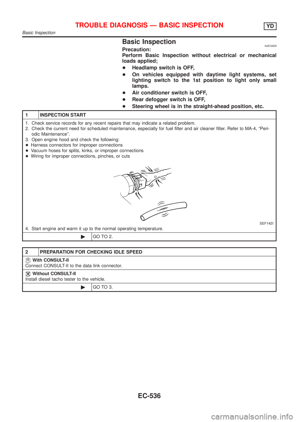
3. Open engine hood and check the following:
+Harness connectors for improper connections
+Vacuum hoses for splits, kinks, or improper connections
+Wiring for improper connections, pinches, or cuts
SEF142I
4. Start engine and warm it up to the normal operating temperature.
©GO TO 2.
2 PREPARATION FOR CHECKING IDLE SPEED
With CONSULT-II
Connect CONSULT-II to the data link connector.
Without CONSULT-II
Install diesel tacho tester to the vehicle.
©GO TO 3.
TROUBLE DIAGNOSIS Ð BASIC INSPECTIONYD
Basic Inspection
EC-536
Page 1193 of 2493
Supplemental Restraint System (SRS) ªAIR
BAGº and ªSEAT BELT PRE-TENSIONERº
NJAT0249The Supplemental Restraint System such as ªAIR BAGº and ªSEAT BELT PRE-TENSIONERº used along with
a seat belt, helps to reduce the risk or severity of injury to the driver and front passenger for certain types of
collision. The SRS system composition which is available to NISSAN MODEL N16 is as follows (The compo-
sition varies according to the destination and optional equipment.):
+For a frontal collision
The Supplemental Restraint System consists of driver air bag module (located in the center of the steer-
ing wheel), front passenger air bag module (located on the instrument panel on passenger side), front seat
belt pre-tensioners, a diagnosis sensor unit, warning lamp, wiring harness and spiral cable.
+For a side collision
The Supplemental Restraint System consists of front side air bag module (located in the outer side of front
seat), side air bag (satellite) sensor, diagnosis sensor unit (one of components of air bags for a frontal
collision), wiring harness, warning lamp (one of components of air bags for a frontal collision).
Information necessary to service the system safely is included in theRS sectionof this Service Manual.
WARNING:
+To avoid rendering the SRS inoperative, which could increase the risk of personal injury or death
in the event of a collision which would result in air bag inflation, all maintenance should be per-
formed by an authorized NISSAN dealer.
+Improper maintenance, including incorrect removal and installation of the SRS, can lead to per-
sonal injury caused by unintentional activation of the system. For removal of Spiral Cable and Air
Bag Module, see the RS section.
+Do not use electrical test equipment on any circuit related to the SRS unless instructed to in this
Service Manual. Spiral cable and wiring harnesses covered with yellow insulation tape either just
before the harness connectors or for the complete harness are related to the SRS.
Precautions for On Board Diagnostic (EURO-
OBD) System of A/T and Engine Ð Euro-OBD
Ð
NJAT0245The ECM has an on board diagnostic system. It will light up the malfunction indicator lamp (MIL) to warn the
driver of a malfunction causing emission deterioration.
CAUTION:
+Be sure to turn the ignition switch ªOFFº and disconnect the negative battery terminal before any
repair or inspection work. The open/short circuit of related switches, sensors, solenoid valves, etc.
will cause the MIL to light up.
+Be sure to connect and lock the connectors securely after work. A loose (unlocked) connector will
cause the MIL to light up due to an open circuit. (Be sure the connector is free from water, grease,
dirt, bent terminals, etc.)
+Be sure to route and secure the harnesses properly after work. Interference of the harness with a
bracket, etc. may cause the MIL to light up due to a short circuit.
+Be sure to connect rubber tubes properly after work. A misconnected or disconnected rubber tube
may cause the MIL to light up due to a malfunction of the EGR system or fuel injection system,
etc.
+Be sure to erase the unnecessary malfunction information (repairs completed) from the TCM and
ECM before returning the vehicle to the customer.
SEF289H
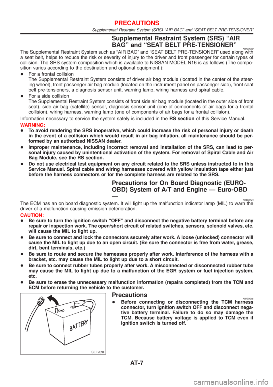
PrecautionsNJAT0246+Before connecting or disconnecting the TCM harness
connector, turn ignition switch OFF and disconnect nega-
tive battery terminal. Failure to do so may damage the
TCM. Because battery voltage is applied to TCM even if
ignition switch is turned off.
PRECAUTIONS
Supplemental Restraint System (SRS) ªAIR BAGº and ªSEAT BELT PRE-TENSIONERº
AT-7
Page 1668 of 2493
Wheel Hub
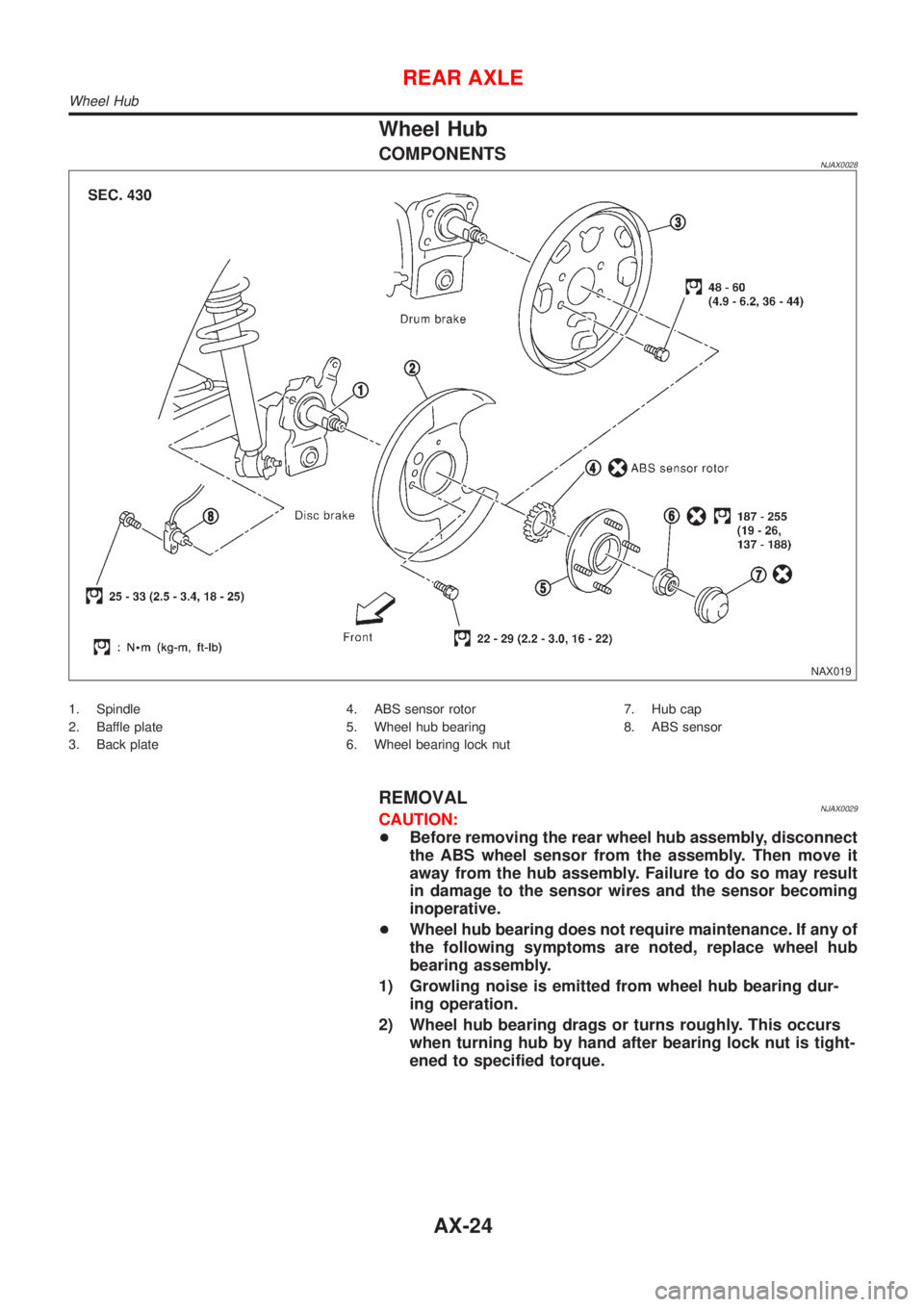
COMPONENTSNJAX0028
NAX019
1. Spindle
2. Baffle plate
3. Back plate4. ABS sensor rotor
5. Wheel hub bearing
6. Wheel bearing lock nut7. Hub cap
8. ABS sensor
REMOVALNJAX0029CAUTION:
+Before removing the rear wheel hub assembly, disconnect
the ABS wheel sensor from the assembly. Then move it
away from the hub assembly. Failure to do so may result
in damage to the sensor wires and the sensor becoming
inoperative.
+Wheel hub bearing does not require maintenance. If any of
the following symptoms are noted, replace wheel hub
bearing assembly.
1) Growling noise is emitted from wheel hub bearing dur-
ing operation.
2) Wheel hub bearing drags or turns roughly. This occurs
when turning hub by hand after bearing lock nut is tight-
ened to specified torque.
REAR AXLE
Wheel Hub
AX-24
Page 1701 of 2493
Supplemental Restraint System (SRS) ªAIR
BAGº and ªSEAT BELT PRE-TENSIONERº
NJBR0139The Supplemental Restraint System such as ªAIR BAGº and ªSEAT BELT PRE-TENSIONERº used along with
a seat belt, helps to reduce the risk or severity of injury to the driver and front passenger for certain types of
collision. The SRS system composition which is available to NISSAN MODEL N16 is as follows (The compo-
sition varies according to the destination and optional equipment.):
+For a frontal collision
The Supplemental Restraint System consists of driver air bag module (located in the center of the steer-
ing wheel), front passenger air bag module (located on the instrument panel on passenger side), front seat
belt pre-tensioners, a diagnosis sensor unit, warning lamp, wiring harness and spiral cable.
+For a side collision
The Supplemental Restraint System consists of front side air bag module (located in the outer side of front
seat), side air bag (satellite) sensor, diagnosis sensor unit (one of components of air bags for a frontal
collision), wiring harness, warning lamp (one of components of air bags for a frontal collision).
Information necessary to service the system safely is included in theRS sectionof this Service Manual.
WARNING:
+To avoid rendering the SRS inoperative, which could increase the risk of personal injury or death
in the event of a collision which would result in air bag inflation, all maintenance should be per-
formed by an authorized NISSAN dealer.
+Improper maintenance, including incorrect removal and installation of the SRS, can lead to per-
sonal injury caused by unintentional activation of the system. For removal of Spiral Cable and Air
Bag Module, see the RS section.
+Do not use electrical test equipment on any circuit related to the SRS unless instructed to in this
Service Manual. SRS wiring harnesses can be identified by yellow harness connector.
SBR686C
Precautions for Brake SystemNJBR0002+Recommended fluid is brake fluid ªDOT 4º.
+Never reuse drained brake fluid.
+Be careful not to splash brake fluid on painted areas.
+To clean or wash all parts of master cylinder, disc brake
caliper and wheel cylinder, use clean brake fluid.
+Never use mineral oils such as gasoline or kerosene. They
will ruin rubber parts of the hydraulic system.
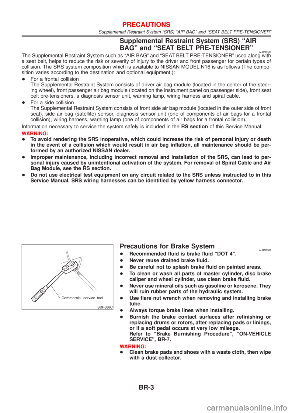
+Use flare nut wrench when removing and installing brake
tube.
+Always torque brake lines when installing.
+Burnish the brake contact surfaces after refinishing or
replacing drums or rotors, after replacing pads or linings,
or if a soft pedal occurs at very low mileage.
Refer to ªBrake Burnishing Procedureº, ªON-VEHICLE
SERVICEº, BR-7.
WARNING:
+Clean brake pads and shoes with a waste cloth, then wipe
with a dust collector.
PRECAUTIONS
Supplemental Restraint System (SRS) ªAIR BAGº and ªSEAT BELT PRE-TENSIONERº
BR-3
Page 1792 of 2493
Supplemental Restraint System (SRS) ªAIR
BAGº and ªSEAT BELT PRE-TENSIONERº
NJST0044The Supplemental Restraint System such as ªAIR BAGº and ªSEAT BELT PRE-TENSIONERº used along with
a seat belt, helps to reduce the risk or severity of injury to the driver and front passenger for certain types of
collision. The SRS system composition which is available to NISSAN MODEL N16 is as follows (The compo-
sition varies according to the destination and optional equipment.):
+For a frontal collision
The Supplemental Restraint System consists of driver air bag module (located in the center of the steer-
ing wheel), front passenger air bag module (located on the instrument panel on passenger side), front seat
belt pre-tensioners, a diagnosis sensor unit, warning lamp, wiring harness and spiral cable.
+For a side collision
The Supplemental Restraint System consists of front side air bag module (located in the outer side of front
seat), side air bag (satellite) sensor, diagnosis sensor unit (one of components of air bags for a frontal
collision), wiring harness, warning lamp (one of components of air bags for a frontal collision).
Information necessary to service the system safely is included in theRS sectionof this Service Manual.
WARNING:
+To avoid rendering the SRS inoperative, which could increase the risk of personal injury or death
in the event of a collision which would result in air bag inflation, all maintenance should be per-
formed by an authorized NISSAN dealer.
+Improper maintenance, including incorrect removal and installation of the SRS, can lead to per-
sonal injury caused by unintentional activation of the system. For removal of Spiral Cable and Air
Bag Module, see the RS section.
+Do not use electrical test equipment on any circuit related to the SRS unless instructed to in this
Service Manual. SRS wiring harnesses (except ªSEAT BELT PRE-TENSIONERº connector) can be
identified by yellow harness connector.
Precautions for Steering SystemNJST0003+Before disassembly, thoroughly clean the outside of the unit.
+Disassembly should be done in a clean work area. It is important to prevent the internal parts from
becoming contaminated by dirt or other foreign matter.
+Place disassembled parts in order, on a parts rack, for easier and proper assembly.
+Use nylon cloths or paper towels to clean the parts; common shop rags can leave lint that might
interfere with their operation.
+Before inspection or reassembly, carefully clean all parts with a general purpose, non-flammable
solvent.
+Before assembly, apply a coat of recommended power steering fluid* to hydraulic parts. Vaseline
may be applied to O-rings and seals. Do not use any grease.
+Replace all gaskets, seals and O-rings. Avoid damaging O-rings, seals and gaskets during instal-
lation. Perform functional tests whenever designated.
*: DEXRON
TMIII or equivalent. Refer to MA-20, ªFluids and Lubricantsº.
PRECAUTIONS
Supplemental Restraint System (SRS) ªAIR BAGº and ªSEAT BELT PRE-TENSIONERº
ST-2